
Beam test of FARICH prototype with DPC d
Beam test of FARICH prototype with DPC (d. Si. PM) Presented by Sergey Kononov (BINP) A. Yu. Barnyakov, M. Yu. Barnyakov, V. S. Bobrovnikov, A. R. Buzykaev, V. V. Gulevich, S. A. Kononov, E. A. Kravchenko, I. A. Kuyanov, A. P. Onuchin, I. V. Ovtin, A. A. Talyshev Budker Institute of Nuclear Physics, Novosibirsk, Russia A. F. Danilyuk Boreskov Institute of Catalysis SB RAS, Novosibirsk, Russia D. A. Finogeev, T. L. Karavicheva, A. B. Kurepin, V. I. Razin, A. I. Reshetin, E. A. Usenko Institute of Nuclear Research RAS, Moscow, Russia C. Degenhardt, R. Dorscheid , T. Frach, O. Muelhens, R. Schulze, B. Zwaans, Philips Digital Photon Counting, Aachen, Germany
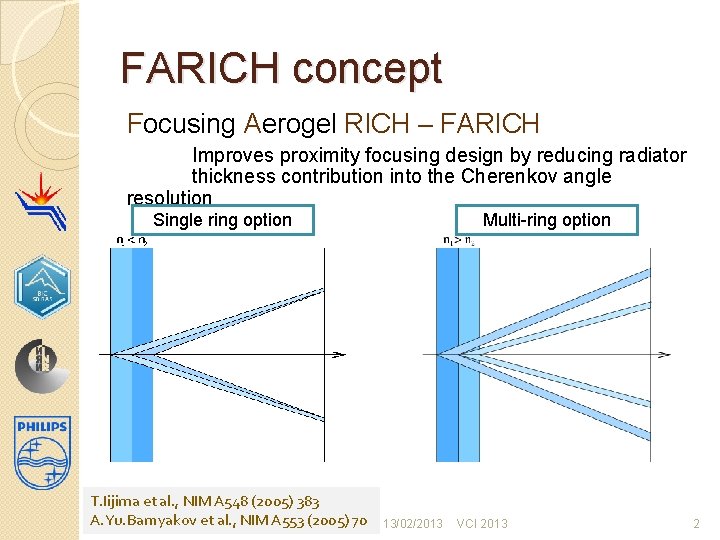
FARICH concept Focusing Aerogel RICH – FARICH Improves proximity focusing design by reducing radiator thickness contribution into the Cherenkov angle resolution Single ring option T. Iijima et al. , NIM A 548 (2005) 383 A. Yu. Barnyakov et al. , NIM A 553 (2005) 70 Multi-ring option 13/02/2013 VCI 2013 2
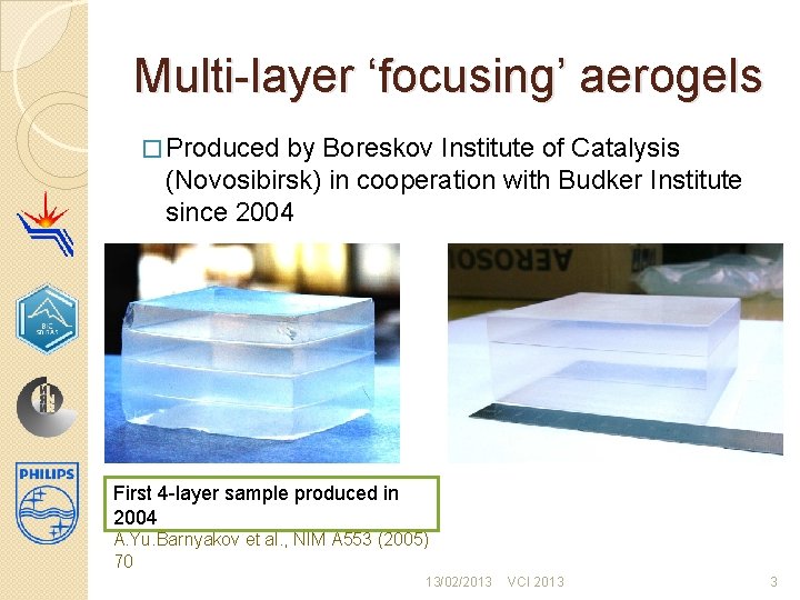
Multi-layer ‘focusing’ aerogels � Produced by Boreskov Institute of Catalysis (Novosibirsk) in cooperation with Budker Institute since 2004 First 4 -layer sample produced in 2004 A. Yu. Barnyakov et al. , NIM A 553 (2005) 70 13/02/2013 VCI 2013 3

FARICH projects and proposals. FARICH for Super Charm-Tau Factory (Novosibirsk) Particle ID: μ/π up to 1. 7 Ge. V/c 21 m 2 detector area (Si. PMs) ~1 M channels FARICH for ALICE HMPID upgrade Particle ID: π/K up to 10 Ge. V/с, K/p up to 15 Ge. V/c 3 m 2 detector area (Si. PMs) Forward Spectrometer RICH for PANDA Particle ID: π/K/p up to 10 Ge. V/с 3 m 2 detector area (Ma. PMTs or Si. PMs) 13/02/2013 VCI 2013 4
Philips Digital Photon Counting (PDPC) Philips Digital Photon Counting is designing and manufacturing scalable detectors based on digital Silicon Photomultiplier (d. Si. PM) technology – a new type of advanced solid state light detector, now called Digital Photon Counter (DPC). Potential Applications • Medical Imaging • Life Sciences • High Energy Physics • Material Testing/Detection • Process Control 13/02/2013 VCI 2013 5
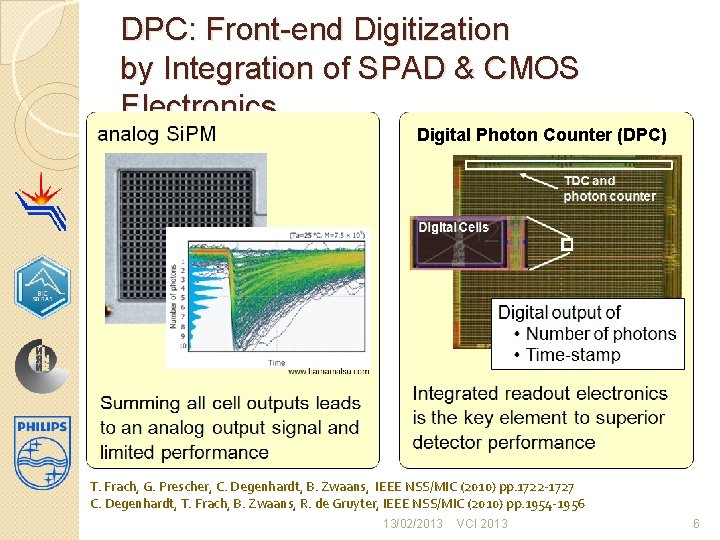
DPC: Front-end Digitization by Integration of SPAD & CMOS Electronics Digital Photon Counter (DPC) T. Frach, G. Prescher, C. Degenhardt, B. Zwaans, IEEE NSS/MIC (2010) pp. 1722 -1727 C. Degenhardt, T. Frach, B. Zwaans, R. de Gruyter, IEEE NSS/MIC (2010) pp. 1954 -1956 13/02/2013 VCI 2013 6
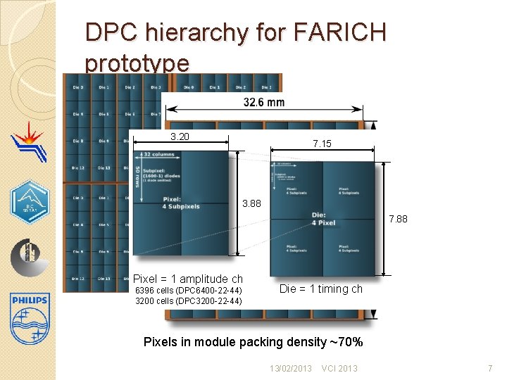
DPC hierarchy for FARICH prototype 3. 20 7. 15 Module 3. 88 Tile Pixel = 1 amplitude ch 6396 cells (DPC 6400 -22 -44) 3200 cells (DPC 3200 -22 -44) 7. 88 Die = 1 timing ch Pixels in module packing density ~70% 13/02/2013 VCI 2013 7
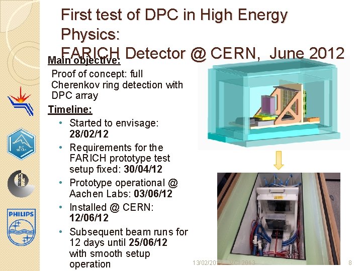
First test of DPC in High Energy Physics: FARICH Detector @ CERN, June 2012 Main objective: Proof of concept: full Cherenkov ring detection with DPC array Timeline: • Started to envisage: 28/02/12 • Requirements for the FARICH prototype test setup fixed: 30/04/12 • Prototype operational @ Aachen Labs: 03/06/12 • Installed @ CERN: 12/06/12 • Subsequent beam runs for 12 days until 25/06/12 with smooth setup 13/02/2013 operation VCI 2013 8
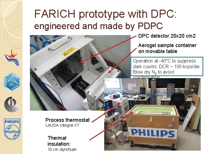
FARICH prototype with DPC: engineered and made by PDPC detector 20 x 20 cm 2 Aerogel sample container on movable table Operation at -40°C to suppress dark counts: DCR ~ 100 kcps/die. Blow dry N 2 to avoid condensation. Process thermostat LAUDA Integral XT Thermal insulation: 10 cm styrofoam 13/02/2013 VCI 2013 9
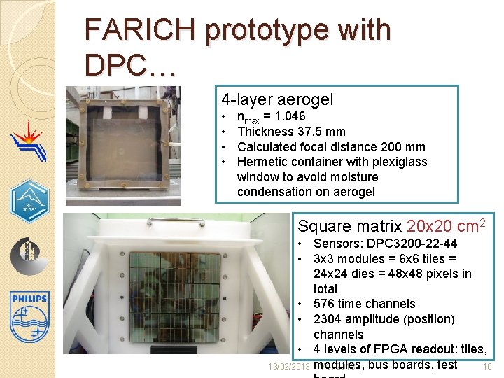
FARICH prototype with DPC… 4 -layer aerogel • • nmax = 1. 046 Thickness 37. 5 mm Calculated focal distance 200 mm Hermetic container with plexiglass window to avoid moisture condensation on aerogel Square matrix 20 cm 2 • Sensors: DPC 3200 -22 -44 • 3 x 3 modules = 6 x 6 tiles = 24 x 24 dies = 48 x 48 pixels in total • 576 time channels • 2304 amplitude (position) channels • 4 levels of FPGA readout: tiles, 13/02/2013 modules, bus boards, test VCI 2013 10
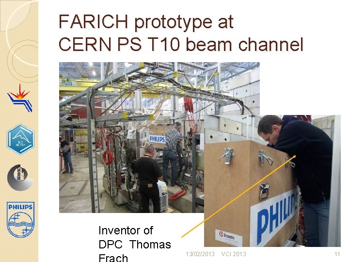
FARICH prototype at CERN PS T 10 beam channel Inventor of DPC Thomas 13/02/2013 VCI 2013 11
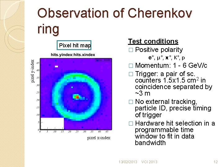
Observation of Cherenkov ring Pixel hit map Test conditions � Positive polarity pixel y-index e+, μ+, π+, K+, p � Momentum: 1 - 6 Ge. V/c � Trigger: a pair of sc. pixel x-index counters 1. 5 x 1. 5 cm 2 in coincidence separated by ~3 m � No external tracking, particle ID, precise timing of trigger � Hardware hit selection in a programmable time window to fit in data bandwidth 13/02/2013 VCI 2013 12
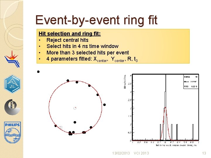
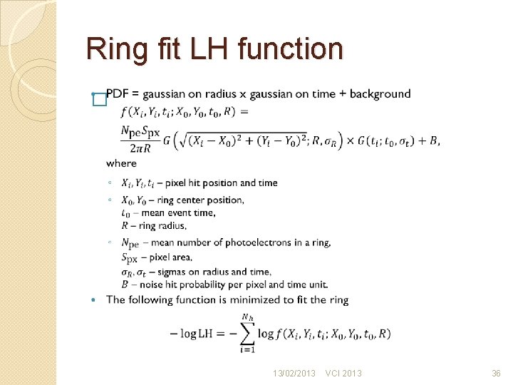
Event-by-event ring fit Hit selection and ring fit: • Reject central hits • Select hits in 4 ns time window • More than 3 selected hits per event • 4 parameters fitted: Xcenter, Ycenter, R, t 0 13/02/2013 VCI 2013 13
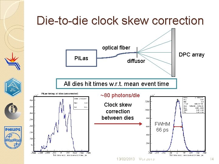
Die-to-die clock skew correction optical fiber Pi. Las DPC array diffusor All dies hit times w. r. t. mean event time ~80 photons/die Clock skew correction between dies FWHM 66 ps 13/02/2013 VCI 2013 14
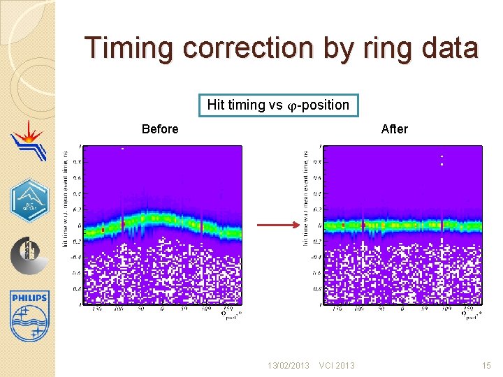
Timing correction by ring data Hit timing vs φ-position Before After 13/02/2013 VCI 2013 15
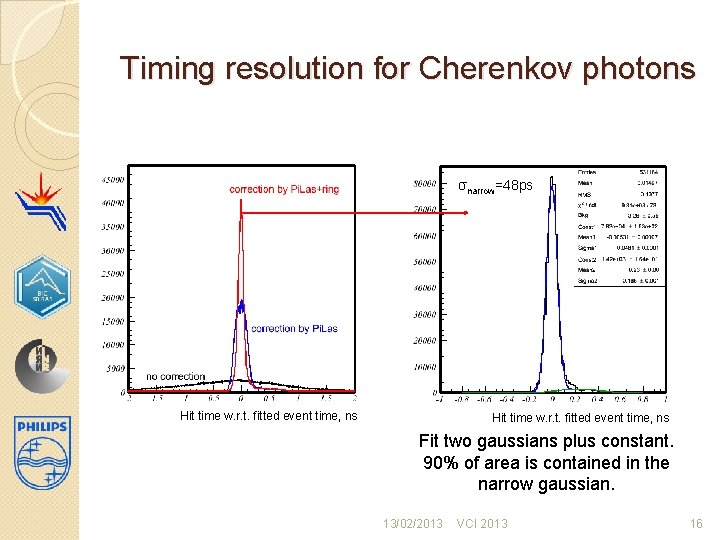
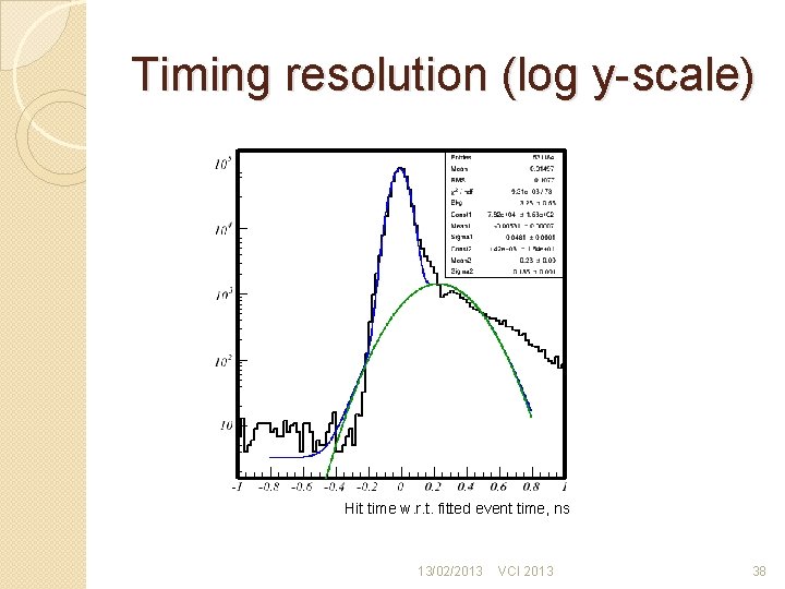
Timing resolution for Cherenkov photons σnarrow=48 ps Hit time w. r. t. fitted event time, ns Fit two gaussians plus constant. 90% of area is contained in the narrow gaussian. 13/02/2013 VCI 2013 16
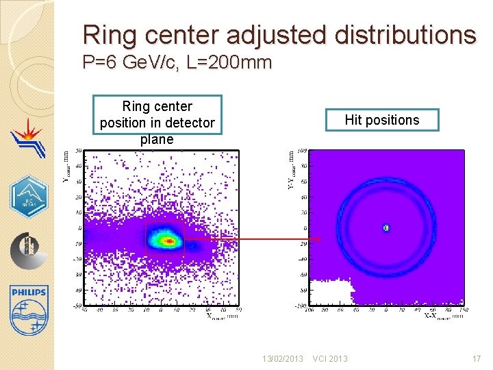
Ring center adjusted distributions P=6 Ge. V/c, L=200 mm Ring center position in detector plane Hit positions 13/02/2013 VCI 2013 17
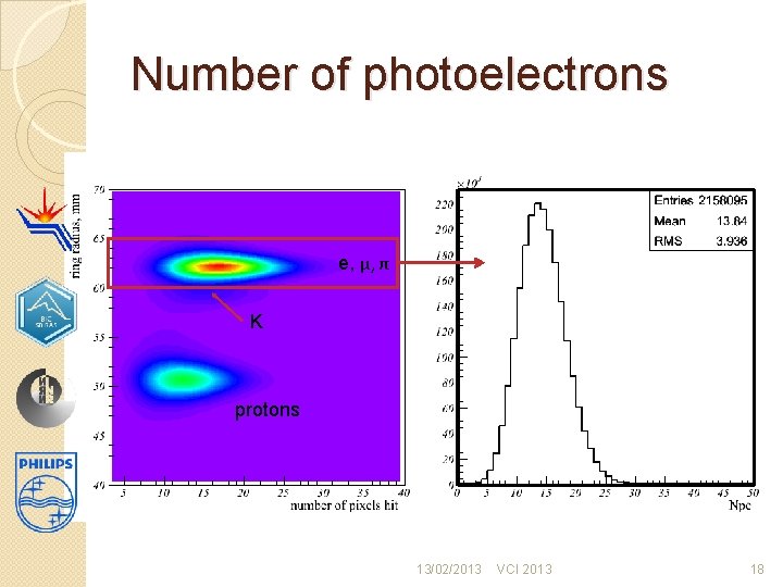
Number of photoelectrons e, μ, π K protons 13/02/2013 VCI 2013 18
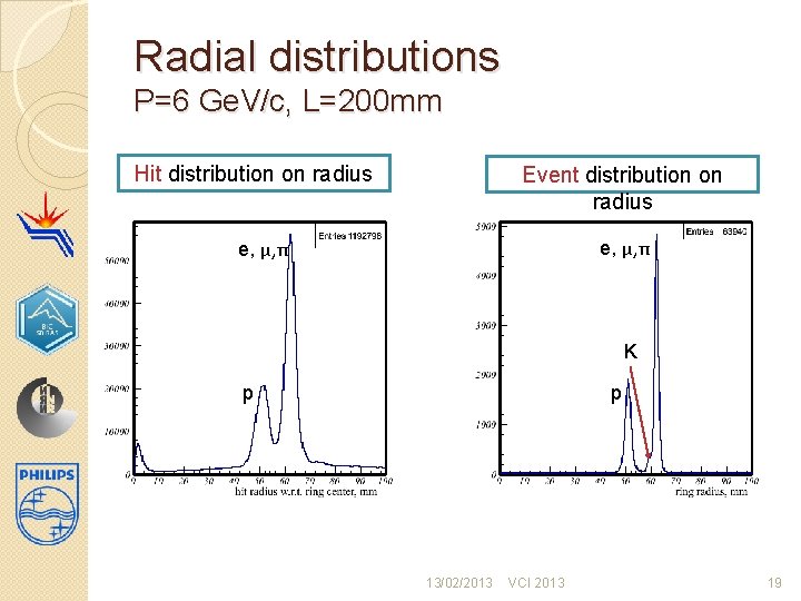
Radial distributions P=6 Ge. V/c, L=200 mm Hit distribution on radius Event distribution on radius e, μ, π K p p 13/02/2013 VCI 2013 19
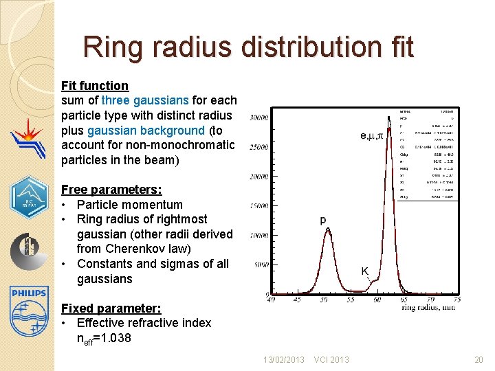
Ring radius distribution fit Fit function sum of three gaussians for each particle type with distinct radius plus gaussian background (to account for non-monochromatic particles in the beam) Free parameters: • Particle momentum • Ring radius of rightmost gaussian (other radii derived from Cherenkov law) • Constants and sigmas of all gaussians Fixed parameter: • Effective refractive index neff=1. 038 13/02/2013 VCI 2013 20
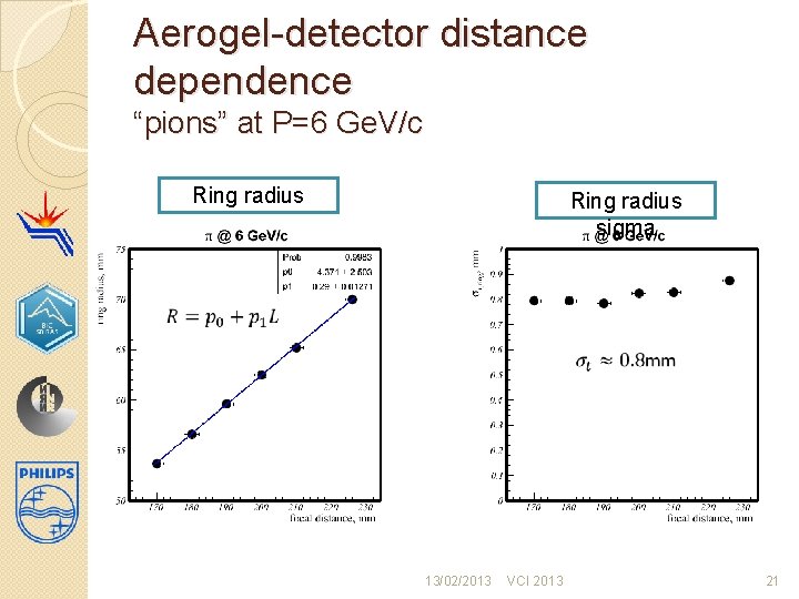
Aerogel-detector distance dependence “pions” at P=6 Ge. V/c Ring radius sigma 13/02/2013 VCI 2013 21
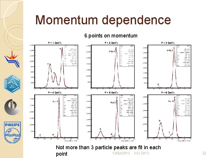
Momentum dependence 6 points on momentum Not more than 3 particle peaks are fit in each 13/02/2013 VCI 2013 point 22
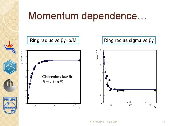
Momentum dependence… Ring radius vs βγ=p/M Ring radius sigma vs βγ 13/02/2013 VCI 2013 23
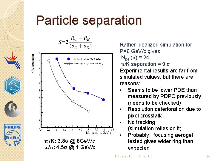
Particle separation π /K: 3. 8σ @ 6 Ge. V/c μ/π: 4. 5σ @ 1 Ge. V/c Rather idealized simulation for P=6 Ge. V/c gives Npe (π) = 24 π/K separation = 9 σ Experimental results are far from simulated values, but there are reasons: • Seems to be lower PDE than measured by PDPC previously (needs to be checked) • Resolution deterioration due to pixel crosstalk • No tracking (simulation relies on it) • Probably: focusing aerogel tested gives wider ring than expected 13/02/2013 VCI 2013 24
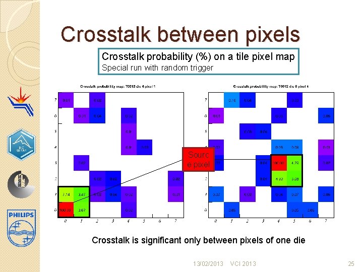
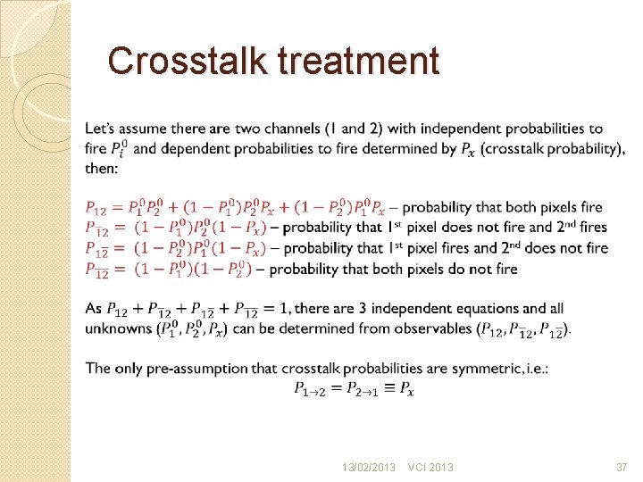
Crosstalk between pixels Crosstalk probability (%) on a tile pixel map Special run with random trigger Sourc e pixel Crosstalk is significant only between pixels of one die 13/02/2013 VCI 2013 25
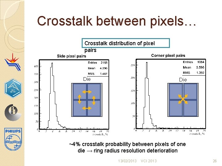
Crosstalk between pixels… Crosstalk distribution of pixel pairs Die ~4% crosstalk probability between pixels of one die → ring radius resolution deterioration 13/02/2013 VCI 2013 26
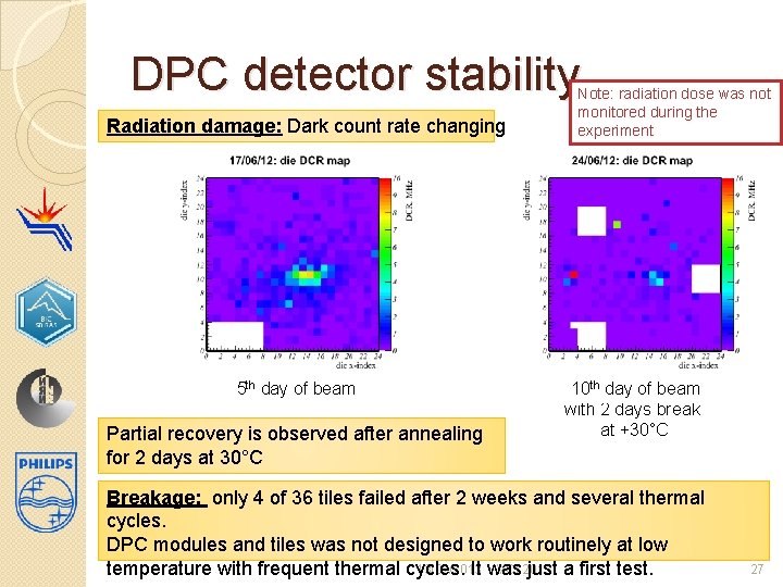
DPC detector stability Radiation damage: Dark count rate changing th day of beam rd Before the beam 23 5 4 nd Partial recovery is observed after annealing for 2 days at 30°C Note: radiation dose was not monitored during the experiment 8 10 day of beam 9 thth day of beam with 2 days break at +30°C Breakage: only 4 of 36 tiles failed after 2 weeks and several thermal cycles. DPC modules and tiles was not designed to work routinely at low 13/02/2013 VCI 2013 temperature with frequent thermal cycles. It was just a first test. 27
Conclusion � Beam test of FARICH prototype with Philips DPC was prepared and successfully realized in a short time scale. � Cherenkov rings are detected from focusing aerogel with ~14 photoelectrons for relativistic particles. � Timing resolution of σt=48 ps is achieved for single Cherenkov photons. � π/K separation obtained for P=6 Ge. V/c is 3. 8σ, μ/π separation is 4. 5σ for P=1 Ge. V/c. � Signs of radiation damage are observed that partially recovered by annealing at room temperature. � Very positive experience of 2 weeks operation of the large and complex setup. � Tests were continued at electron test beam in BINP in January 2013. Results are coming up. 13/02/2013 VCI 2013 28

Thank you for attention! 13/02/2013 VCI 2013 29
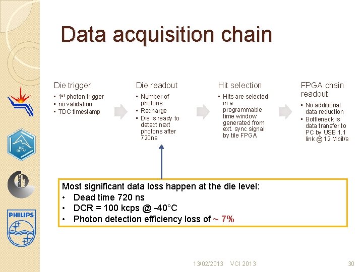
Data acquisition chain Die trigger Die readout Hit selection • 1 st photon trigger • no validation • TDC timestamp • Number of photons • Recharge • Die is ready to detect next photons after 720 ns • Hits are selected in a programmable time window generated from ext. sync signal by tile FPGA chain readout • No additional data reduction • Bottleneck is data transfer to PC by USB 1. 1 link @ 12 Mbit/s Most significant data loss happen at the die level: • Dead time 720 ns • DCR = 100 kcps @ -40°C • Photon detection efficiency loss of ~ 7% 13/02/2013 VCI 2013 30
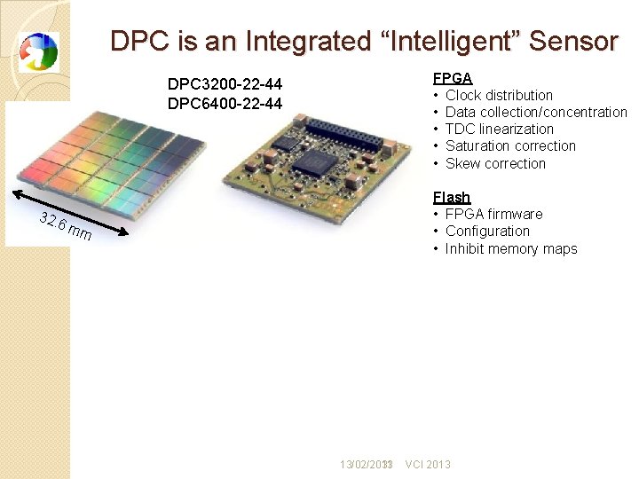
DPC is an Integrated “Intelligent” Sensor FPGA • Clock distribution • Data collection/concentration • TDC linearization • Saturation correction • Skew correction DPC 3200 -22 -44 DPC 6400 -22 -44 32. 6 m Flash • FPGA firmware • Configuration • Inhibit memory maps m 13/02/2013 31 VCI 2013
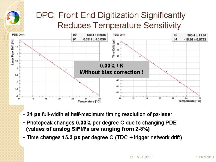
DPC: Front End Digitization Significantly Reduces Temperature Sensitivity 0. 33% / K Without bias correction ! • 24 ps full-width at half-maximum timing resolution of ps-laser • Photopeak changes 0. 33% per degree C due to changing PDE (values of analog Si. PM’s are ranging from 2 -8%) • Time changes 15. 3 ps per degree C (TDC + trigger network drift) 32 VCI 2013 13/02/2013
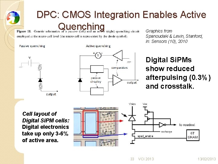
DPC: CMOS Integration Enables Active Quenching Graphics from Spanoudaki & Levin, Stanford, in: Sensors (10), 2010 Digital Si. PMs show reduced afterpulsing (0. 3%) and crosstalk. Cell layout of Digital Si. PM cells: Digital electronics take up only 3 -6% of active area. 33 VCI 2013 13/02/2013
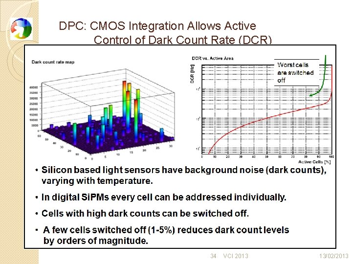
DPC: CMOS Integration Allows Active Control of Dark Count Rate (DCR) 34 VCI 2013 13/02/2013
DPC PDE vs wavelength DPC 3200 -22 -44 13/02/2013 VCI 2013 35
Ring fit LH function � 13/02/2013 VCI 2013 36
Crosstalk treatment 13/02/2013 VCI 2013 37
Timing resolution (log y-scale) Hit time w. r. t. fitted event time, ns 13/02/2013 VCI 2013 38
- Slides: 38