Beam measurement system for BEPCII Jianshe Cao Yanfeng

Beam measurement system for BEPCII Jianshe Cao, Yanfeng Sui On behalf of BI group Hefei, Anhui June 26 -27, 2019

Outline • Introduction • Beam measurement system for BEPCII • The beam measurement development at BEPCII • Summary
 • Was put into operation in")
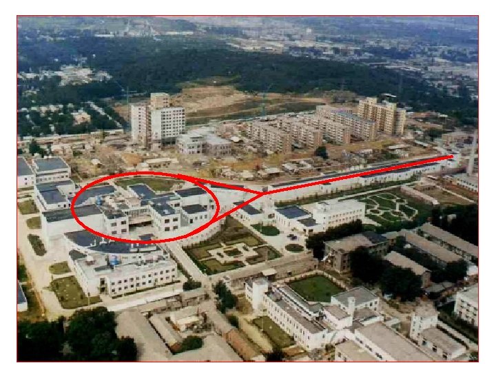
Introduction • Beijing positron and electron collider (BEPC) • Was put into operation in 1989 • Circumference 240 m,Electron/positron beams following a pretzelled orbit in the same ring • Luminosity: 0. 5× 1031@1. 55 Ge. V, 1. 0 × 1031@1. 89 Ge. V • BEPCII:The upgrade project of BEPC • • Was put into operation in 2006 Double rings Cross angel Luminosity: 1. 0 × 1033@1. 89 Ge. V

Beam diagnostics for BEPCII

Beam position monitor 6

Beam position monitor Simulation for Antechamber type BPM The cross-section of the BPM 1. Horizontal center distance between two buttons is 33 mm 2. BPM scale factor Sx and Sy is 25 mm 7

Beam position monitor The mapping bench and sample of vacuum pipe 8

Beam position monitor • MX-BPM signal processing electronics of the Bergoz Company are adopted • The narrow band system for the signal processing Output signal FFT vs. input Mean square error of the output signal vs. input 9

Beam position monitor v MX-BPM COD resolution 10

Beam position monitor • Many upgrades have been done, since the BPM system was built then. • About half of the BPM electronics are replaced by commercial digital BPM for much more advantages in the aspect of programmable bandwidth and extremely wide dynamic range • Home-made DBPM has been tested in BEPCII and will install small amount of electronics in the storage ring in the future.

Beam current monitor • Bergoz type DCCT is employed for the average current monitor. • Bunch current monitor with fast ADC sampling BPM sum signal is used to measure bunch current and share data with injection control system for bucket selection. • There are following two reasons for filling each ring with an equal bunch charge in all bunches: • to optimize the beam-beam tune shift • to control the stability of individual bunches. 12

Beam current monitor Vacuum chamber and shielding of DCCT 13

Beam current monitor The schematic diagram of the front-end circuit Dedicated communication system & shared memory Innovative Integration XG-12 14

Synchrotron light based measurement • The length and transverse size of the light pulse are almost the same as those of the beams. • Synchrotron light is used to measure the transverse beam size, the beam intensity, the bunch length and monitoring beam profile. • In the BEPCII, the synchrotron light emitted in the bending magnet B 10 is reflected horizontally to a side window of the beam pipe by a well-polished copper mirror and then reflected vertically by a remote controllable mirror to the optics building. The distance between the source point and the primary mirror is 1725 mm. 15

Synchrotron light based measurement The 3 D drawing of the special vacuum section Thermal Conductivity Thermal Expansion 0. 392 W/mm C 1. 72 E-5/ C Yield Strength 254 MPa Modulus of Elasticity 108 GPa Poisson Ratio The first Mirror 0. 33 The OFHC specification The power density on the first mirror

Synchrotron light based measurement 17

IP beam position steering system • Beam position automatic steering system based on the beam-beam deflection technique is necessary for maintaining an optimum beam collision condition at the IP. • There are two special BPMs each with 8 button-type electrodes (just like in KEKB) and each of the two special BPMs in common beam pipe. • Finding Beam in the Longitudinal Direction • Horizontal and vertical Beam-Beam Scan • the IP Orbit Feedback The layout of the IP beam position steering system 18
 and the large number")
Feedback system • The high beam current (0. 9 A) and the large number of bunches (93 bunches) may cause the coupled bunch instabilities (CBI) in BEPCII. • Active feedback systems are required to suppress CBI. There are two possible sources of the impedance which gives rise to the CBI: the higher order modes (HOMs) of RF cavities and the resistive wall impedance of the beam pipe. • BEPCII will operate with every other 4 -bucket filled with a bunch spacing of 8 ns (125 -MHz bunch frequency). the growth time of most dangerous CB modes are shorter than the radiation damping time of 12. 5 ms in the longitudinal direction and 25 ms in the transverse direction. • Feedback systems are considered being used in both longitudinal and transverse directions. The design goal of the feedback damping time is set to 5 ms and 2 ms in the longitudinal and transverse directions, respectively. Longitudinal Transverse HOMs 6. 3 ms 26. 6 ms Resistive Wall 4. 3 ms Fastest growing time of CB modes in the case of M = 99, Ib = 9. 8 m. A 19

Transverse feedback Schematic diagram of the TBF system RF frequency Bunch spacing Feedback damping time Detection frequency Number of kickers per plane per ring Kicker shunt impedance (at 250 MHz) Total damping voltage per turn Kicker power for 300 V Number of power amplifiers per plane per ring MHz ns ms GHz Bandpass of power amplifier MHz 0. 01 250 W 25 Output power rating of power amplifier Microwave receiver 499. 8 8 2 1. 5 1 k. W 1. 46 V W 300 31 2 20

Transverse feedback 21
 Schematic diagram of the LFB system RF frequency Bunch spacing Feedback")
Longitudinal feedback (LFB) Schematic diagram of the LFB system RF frequency Bunch spacing Feedback damping time Detection frequency Phase detector dynamic range (at 500 MHz) Phase detector resolution (at 500 MHz) Number of kickers per ring Kicker central frequency Kicker bandwidth Kicker shunt impedance Total damping voltage per turn Kicker power for 600 V Number of power amplifiers per ring Bandpass of power amplifier Output power rating of amplifier Front-end electronics for the longitudinal feedback system MHz ns ms GHz 499. 8 8 5 2 deg. 22. 5 deg. 0. 5 1 1. 125 250 600 300 1 0. 8 - 2. 0 400 GHz MHz W V W GHz W

LFB installation and commissioning Kicker test Amplifier test 23/35

LFB installation and commissioning The Kicker installation online LFB commissioning 24/35

LFB installation and commissioning I=182 m. A,Fastest growing time of mode 63# is 10 ms Assume I=1 A, growing time is about 1 ms

LFB installation and commissioning the sideband is suppressed 26/35

LFB installation and commissioning It is sure that the peak luminosity will increase 30% with the LFB help The bunch luminosity different from head to tail of the bunch train is disappear.

Beam measurement development at BEPCII • • Beam trip analysis by bunch BPM Director diode detection(DDD) tune measurement BPM electronics Bunch cleaning system 28

Beam trip diagnosis The beam trip is an important problem for accelerator operation. It is the hot spot in research for knowing which system caused the beam trip. Because the accelerator system is very complicated, involves many subsystems, and various conditions are mixed together, so, it is difficult to get to the real cause for beam trip. At present, many accelerator all over the world has established a powerful beam trip diagnostic system, such as LHC, PEP-II, RHIC, TLS and so on.

Beam trip in BEPCII storage ring High beam current can cause the beam instability and make devices unstable, thus easily lead to the beam trip. Beam trip seriously affects the efficiency of the machine, also may cause damage to the hardware system. So, it is necessary for BEPCII to develop a diagnostic system for studying the beam trip. • Parameters RF frequency Colliding mode 499. 8 MHz Harmonic number 396 Beam current ~1 A Bunch current 10 m. A Revolution frequency 1. 2621 MHz Cause of beam trip – – n Result of beam trip l l BEPCII double rings layout Subsystem failure RF (trip, LLRF) Beam instabilities … Degrade the operating efficiency Troubleshoot time cost Others subsystem trip …

Bunch-by-bunch system overview • Bunch-by-bunch position measurement prototype for BEPCII ADC: sampling FPGA: BPM and beam trip monitor DDR: data storage and Computing intermediate Electron positron B A Button BPM Signal (50Ω termination) Front-end D C BPM Control and Interface Digital signal process system: (ADC, FPGA, D DR) network computer
. • large")
Front end and sampling • Sampling rate : RF frequency (~500 MHz). • large analogue bandwidth • Achieve high isolation Beam signal Sampling clock Front end and ADC schematic Ideal Sampling schematic

Digital signal process • IN ADC DDR R/W Control Network R/W ADDR OUT FPGA Micro. Blaze DDR

Beam trip research in BEPCII à Beam trip events à more than 300 beam trip events had been collected analysis à Many contrast experiment à Beam trip analysis by bunch-by-bunch system à Time domain and frequency domain à Bunch-by-bunch and turn-by-tune à Tune in three dimensions à Some trip events become clear à RF trip à Magnet power instabilities à Beam instabilities à… Tune S Tune X Tune Y

Summary • The BEPCII beam diagnostics has been developed. After commissioning, it is sure that the system can meet demands of the BEPCII commissioning and operation. • Many upgrades have been done to the beam diagnostics to promote the system performance after the system was build. • Based on the BEPCII, new technologies are verified and developed for future accelerator. 35

Thanks for your attention
- Slides: 36