
Beam Loss Monitors measurements Sara Morales Vigo Technical

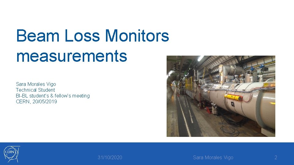
Beam Loss Monitors measurements Sara Morales Vigo Technical Student BI-BL student’s & fellow’s meeting CERN, 20/05/2019 31/10/2020 Sara Morales Vigo 2
Contents of the presentation • • • Why do we need a BLM system BLM background signal (I) BLM background signal (II) BLM dose signal Analysis of connectivity tests 31/10/2020 Sara Morales Vigo 3
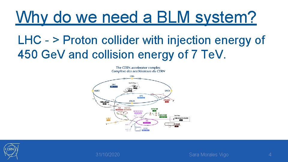
Why do we need a BLM system? LHC - > Proton collider with injection energy of 450 Ge. V and collision energy of 7 Te. V. 31/10/2020 Sara Morales Vigo 4

What is a BLM device? Main active system to prevent damage to magnets and collimators from all possible multiturn losses. 31/10/2020 Sara Morales Vigo 5

Why do we need a BLM system? A loss of a small fraction of the beam particles could cause: • • A quench of the superconducting magnets Physical damage to machine components 31/10/2020 Sara Morales Vigo 6
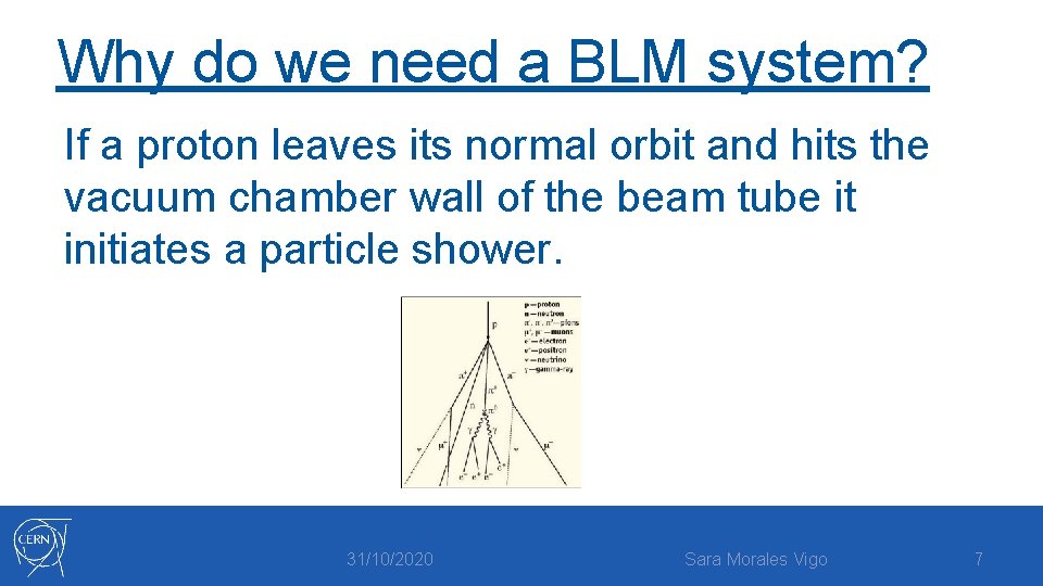
Why do we need a BLM system? If a proton leaves its normal orbit and hits the vacuum chamber wall of the beam tube it initiates a particle shower. 31/10/2020 Sara Morales Vigo 7
What is a BLM system? Beam loss monitors located along the accelerator for: • Measuring the amount of beam losses along an accelerator or storage ring. Unexpected beam losses might prevent circulating beam during commissioning or regular operation of an accelerator. 31/10/2020 Sara Morales Vigo 8
Type of beam losses: Some reasons for a particle loss (unavoidable) • Beam-gas collisions (Residual gas atoms) • Proton-proton collisions (IPs) • Machine imperfections Other avoidable losses are due to: • Orbit drifts, beam instabilities, wrong machine configuration, etc. 31/10/2020 Sara Morales Vigo 9
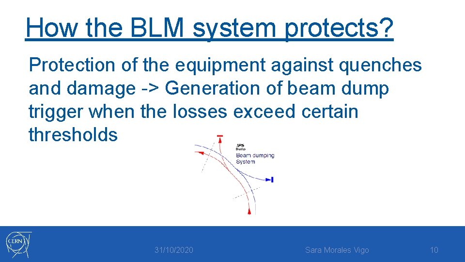
How the BLM system protects? Protection of the equipment against quenches and damage -> Generation of beam dump trigger when the losses exceed certain thresholds 31/10/2020 Sara Morales Vigo 10
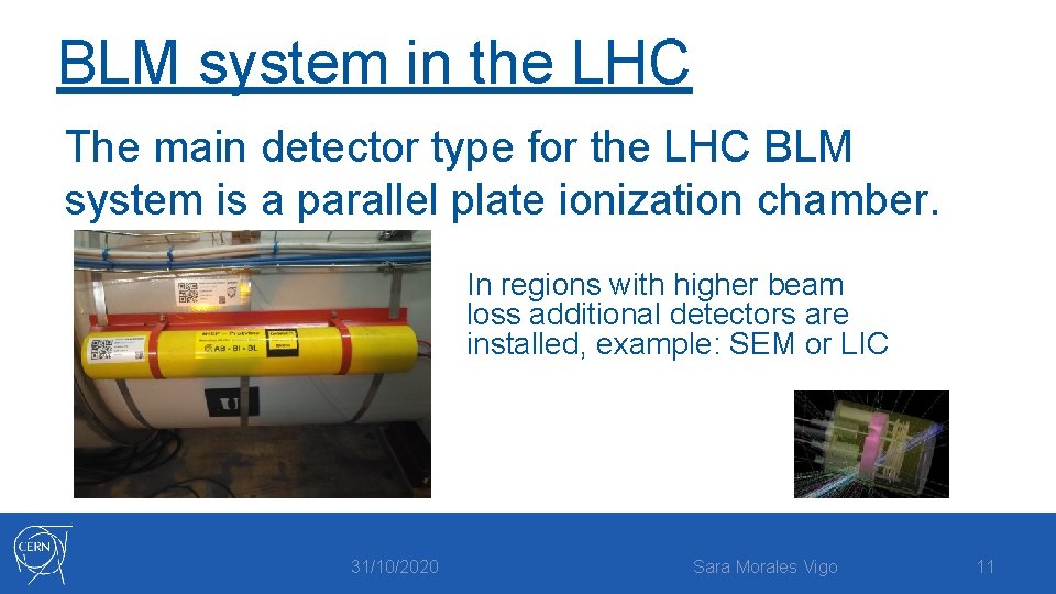
BLM system in the LHC The main detector type for the LHC BLM system is a parallel plate ionization chamber. In regions with higher beam loss additional detectors are installed, example: SEM or LIC 31/10/2020 Sara Morales Vigo 11
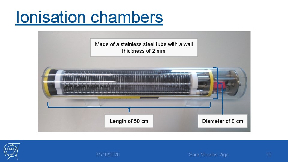
Ionisation chambers Made of a stainless steel tube with a wall thickness of 2 mm Length of 50 cm 31/10/2020 Diameter of 9 cm Sara Morales Vigo 12
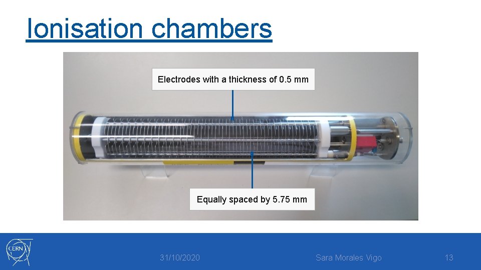
Ionisation chambers Electrodes with a thickness of 0. 5 mm Equally spaced by 5. 75 mm 31/10/2020 Sara Morales Vigo 13
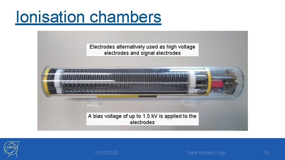
Ionisation chambers Electrodes alternatively used as high voltage electrodes and signal electrodes A bias voltage of up to 1. 5 k. V is applied to the electrodes 31/10/2020 Sara Morales Vigo 14
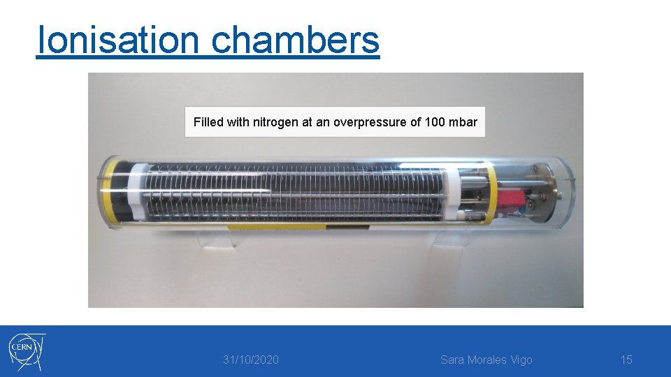
Ionisation chambers Filled with nitrogen at an overpressure of 100 mbar 31/10/2020 Sara Morales Vigo 15
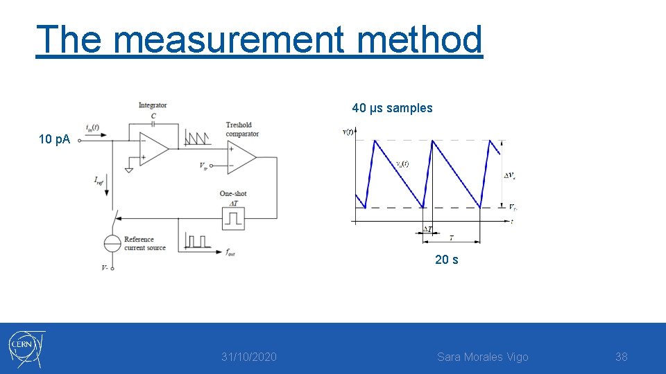
The measurement method The ionisation chambers convert the particle shower caused by mislead protons into an electric current. The amplitude is proportional to the loss rate. 31/10/2020 Sara Morales Vigo 16
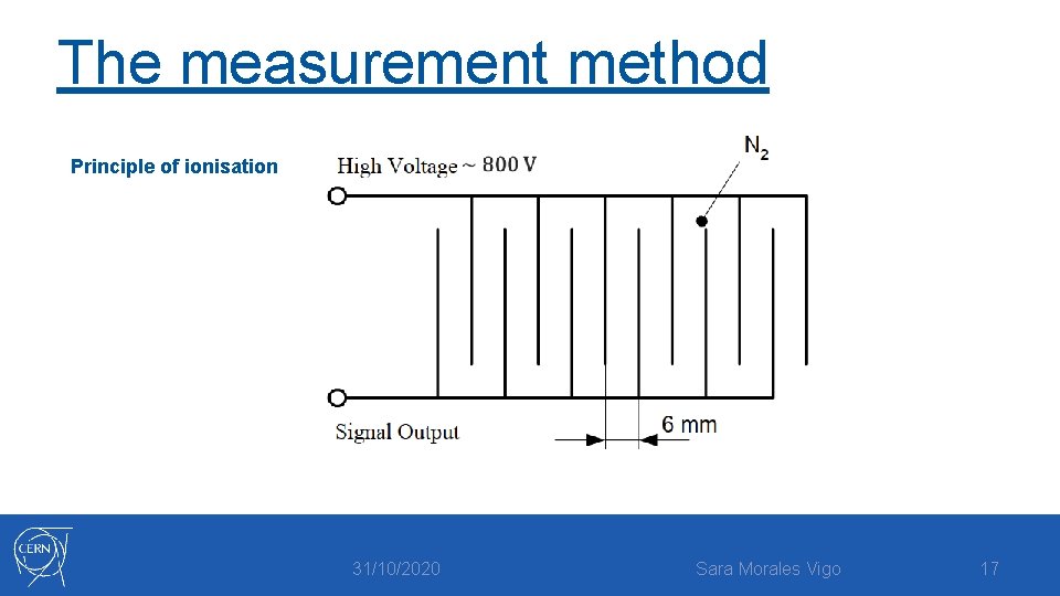
The measurement method Principle of ionisation 31/10/2020 Sara Morales Vigo 17
The measurement method The amplitude of the current depends on: • Number of incoming particles • Volume of the chamber • Length of the particle trace between the electrodes • Gas composition • Gas pressure 31/10/2020 Sara Morales Vigo 18
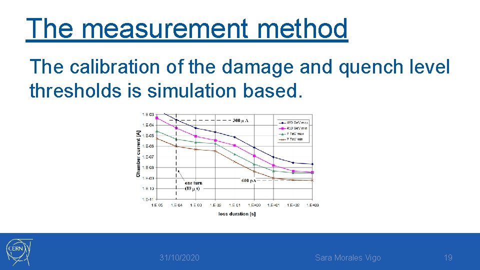
The measurement method The calibration of the damage and quench level thresholds is simulation based. 31/10/2020 Sara Morales Vigo 19
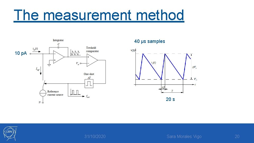
The measurement method 40 μs samples 10 p. A 20 s 31/10/2020 Sara Morales Vigo 20
Where to place the detectors? Beam protons -> likely to be lost at the location where the aperture is minimal: • 450 Ge. V -> Arc quadrupole magnets • 7 Te. V -> Triplet magnets • Collimation sections 31/10/2020 Sara Morales Vigo 21
Where to place the detectors? Detailed Monte Carlo simulations can help find the optimum positions of BLM. The efficiency of a loss detector will be highest if it is located at the maximum of the shower. 31/10/2020 Sara Morales Vigo 22
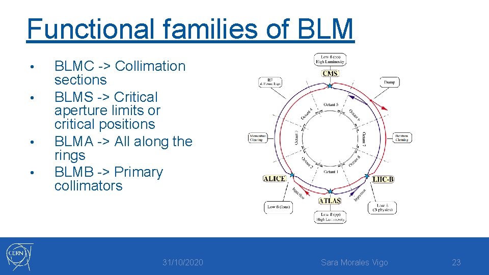
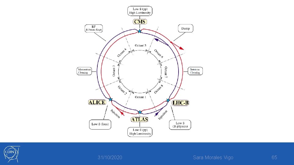
Functional families of BLM • • BLMC -> Collimation sections BLMS -> Critical aperture limits or critical positions BLMA -> All along the rings BLMB -> Primary collimators 31/10/2020 Sara Morales Vigo 23
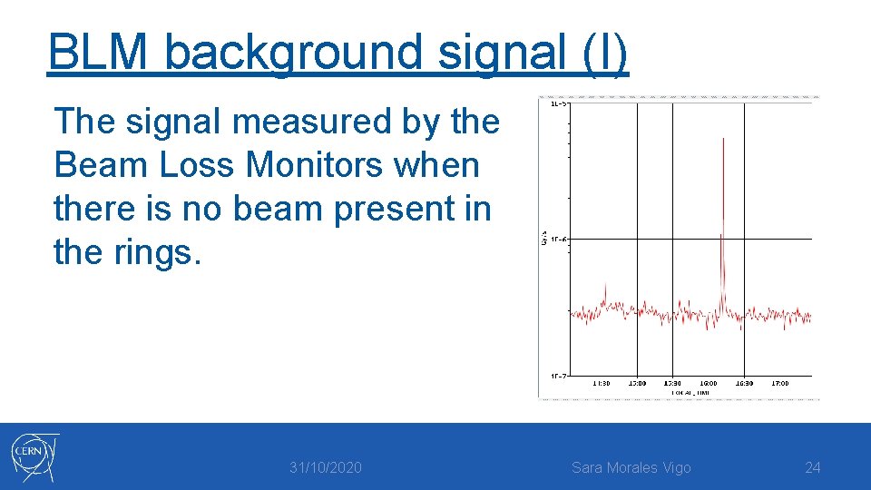
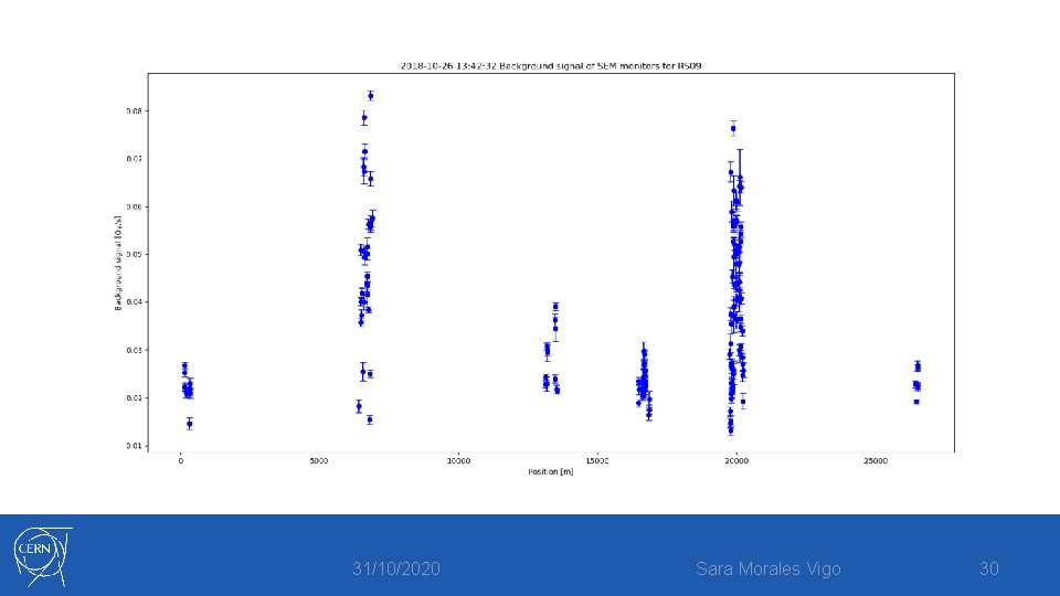
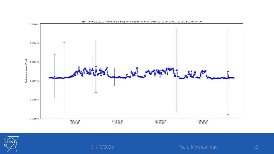
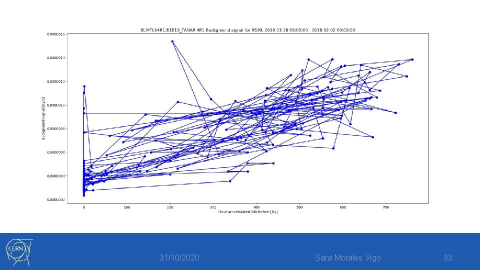
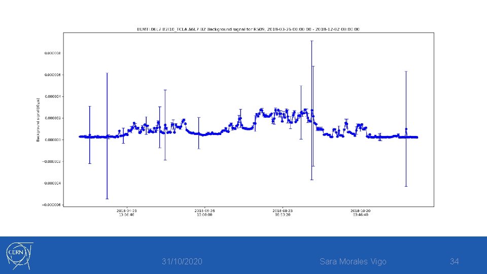
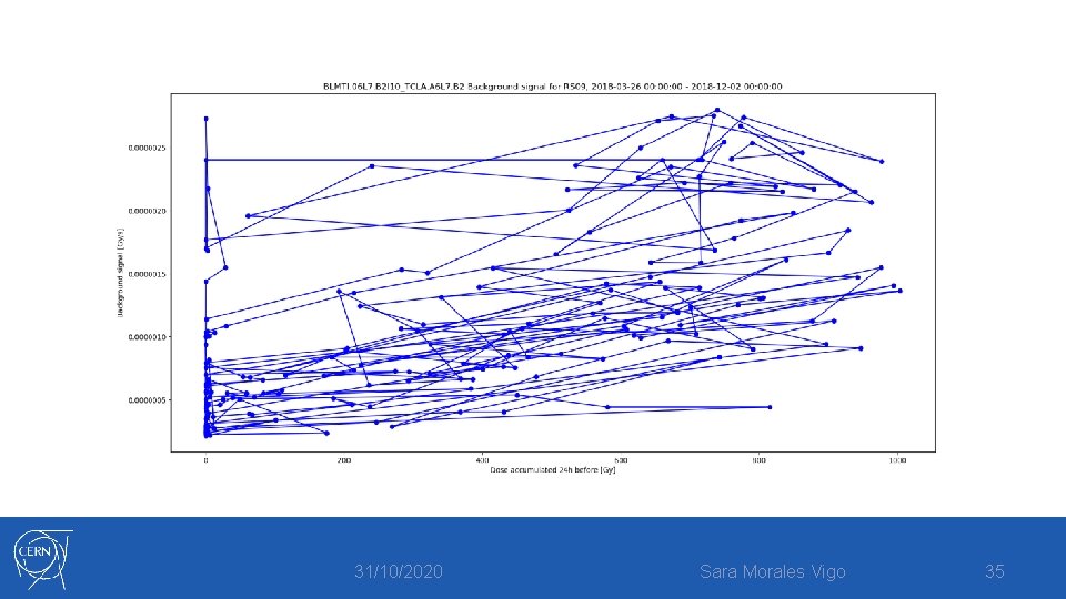
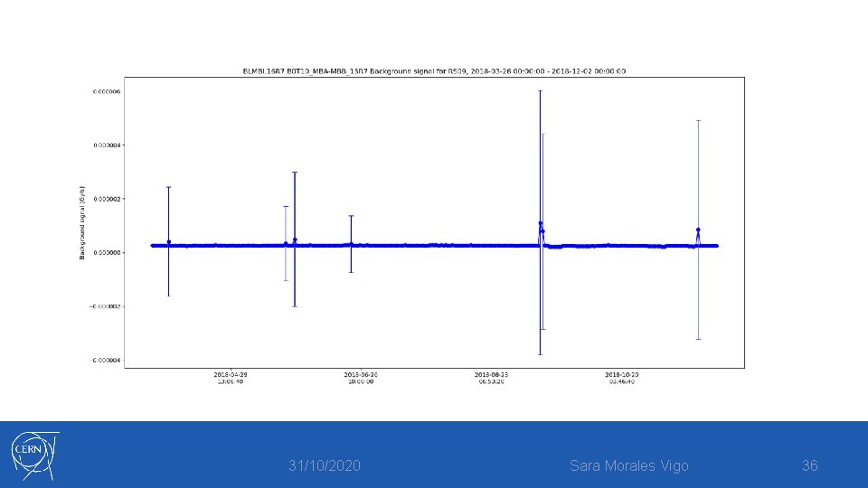
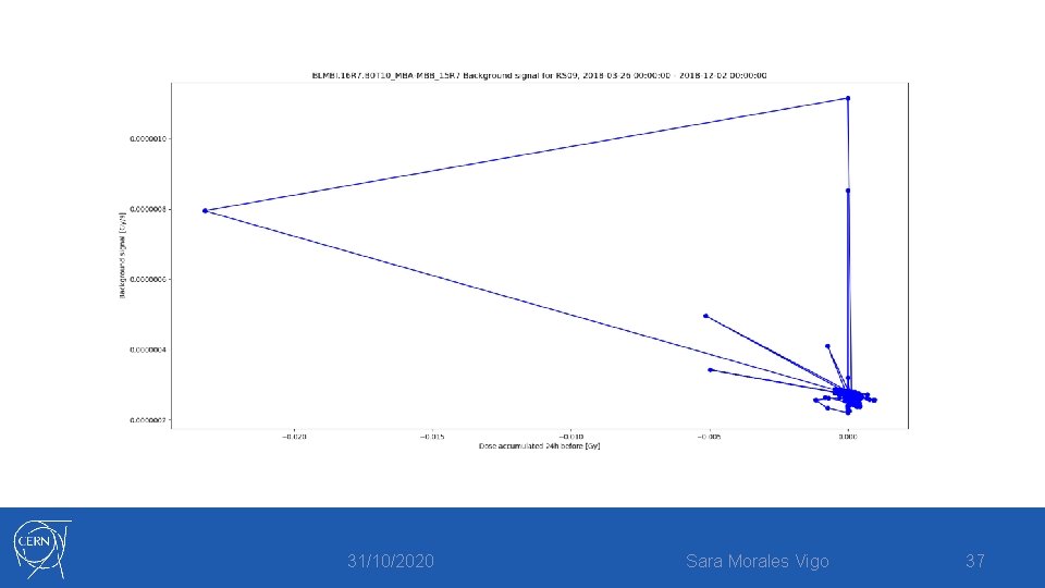
BLM background signal (I) The signal measured by the Beam Loss Monitors when there is no beam present in the rings. 31/10/2020 Sara Morales Vigo 24
BLM background signal (I) How do we measure it? For a given timestamp, we get the mean value of the signal from the closest periods of INJPROT mode before and after, when there is no beam present. • 31/10/2020 Sara Morales Vigo 25
BLM background signal (II) • For a given timestamp and a given RS (Running Sum) 31/10/2020 Sara Morales Vigo 26
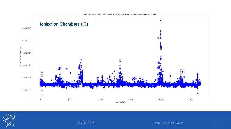
Ionization Chambers (IC) 31/10/2020 Sara Morales Vigo 27
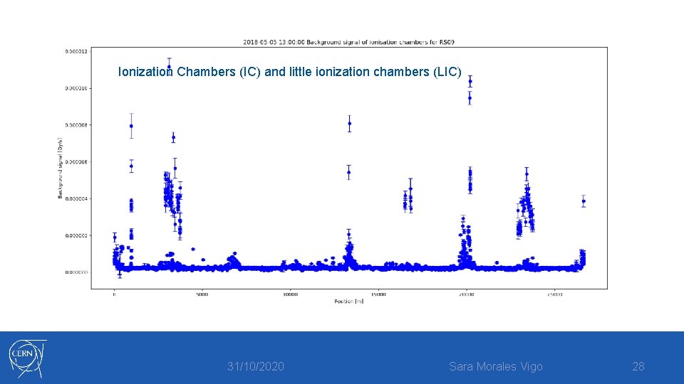
Ionization Chambers (IC) and little ionization chambers (LIC) 31/10/2020 Sara Morales Vigo 28
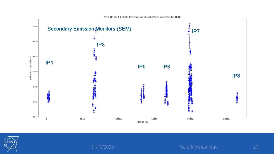
Secondary Emission Monitors (SEM) IP 7 IP 3 IP 1 IP 5 IP 6 IP 8 31/10/2020 Sara Morales Vigo 29
31/10/2020 Sara Morales Vigo 30
BLM background signal (II) • For a given monitor and RS in a determined interval of time: 31/10/2020 Sara Morales Vigo 31
31/10/2020 Sara Morales Vigo 32
31/10/2020 Sara Morales Vigo 33
31/10/2020 Sara Morales Vigo 34
31/10/2020 Sara Morales Vigo 35
31/10/2020 Sara Morales Vigo 36
31/10/2020 Sara Morales Vigo 37
The measurement method 40 μs samples 10 p. A 20 s 31/10/2020 Sara Morales Vigo 38
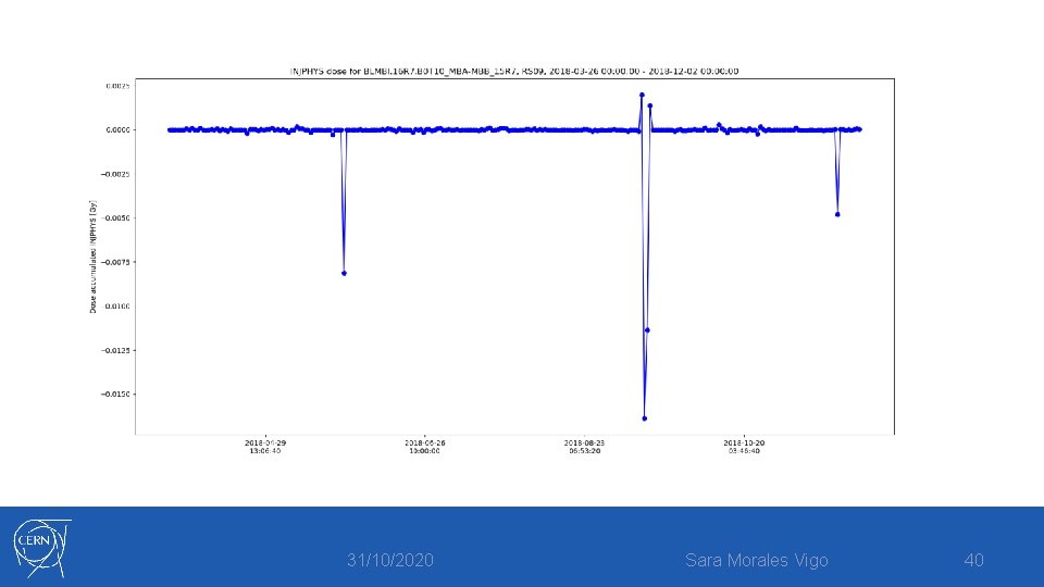
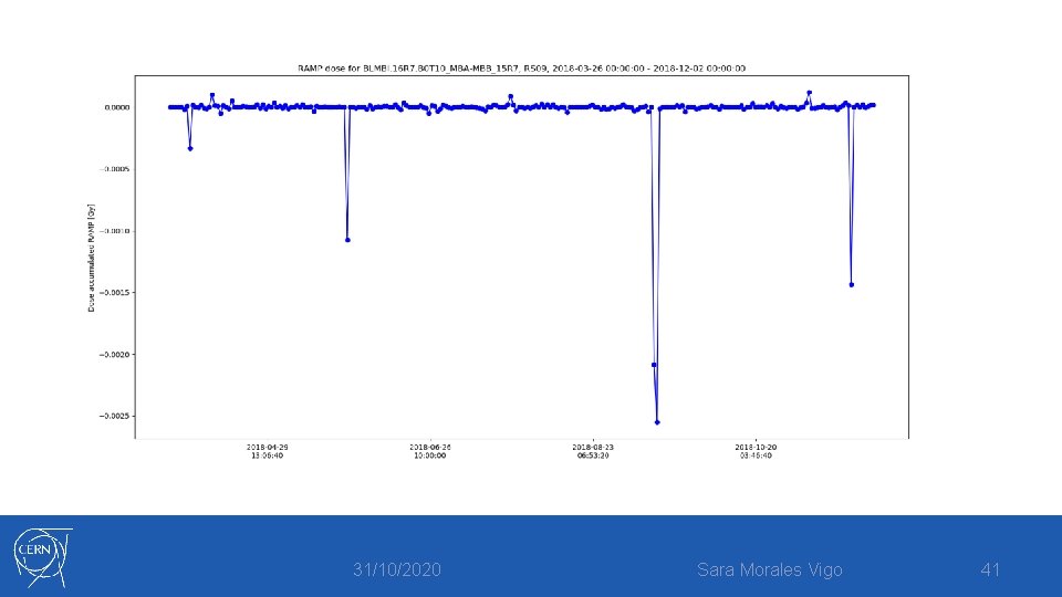
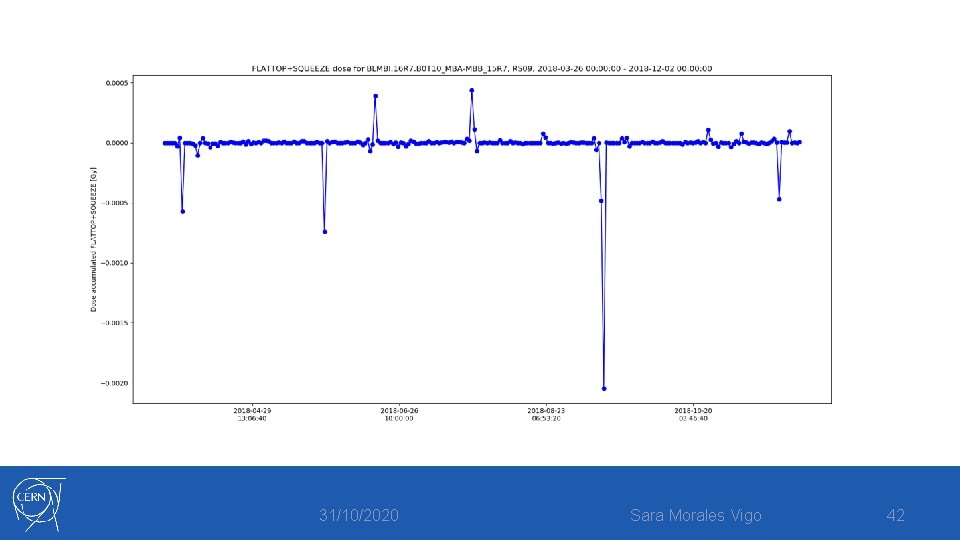
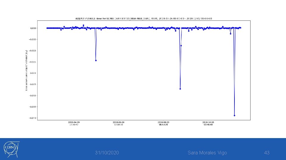
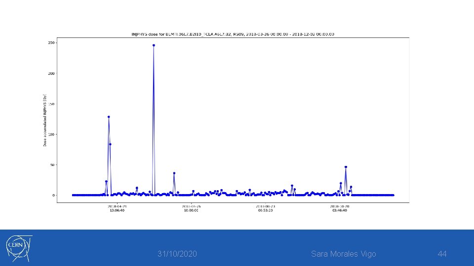
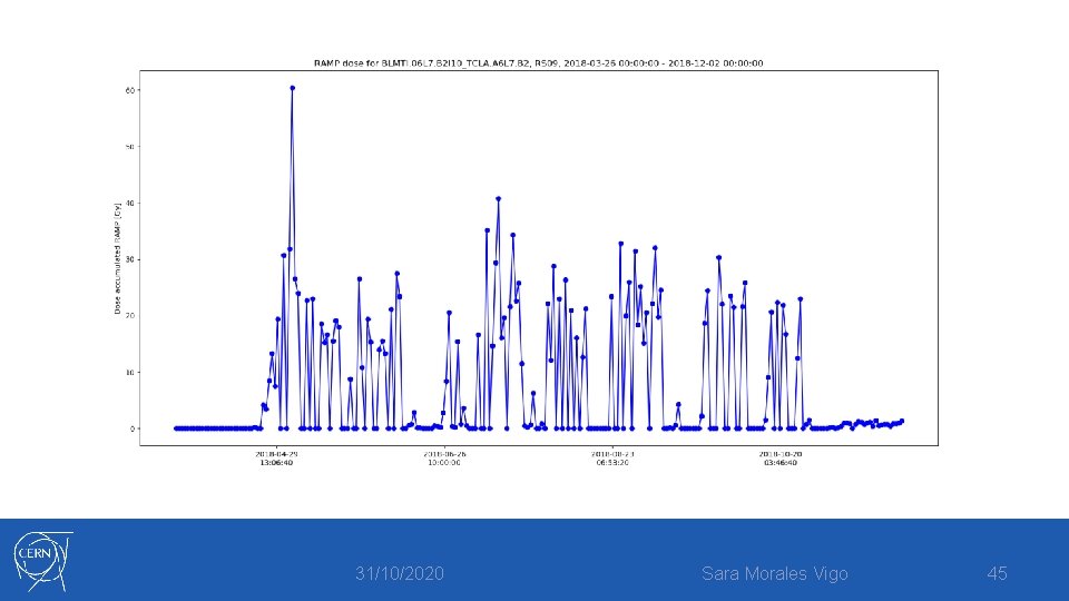
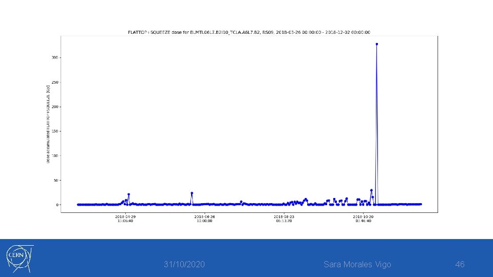
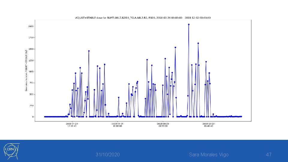
BLM signal • For a given monitor and RS in a determined interval of time per beam mode: 31/10/2020 Sara Morales Vigo 39
31/10/2020 Sara Morales Vigo 40
31/10/2020 Sara Morales Vigo 41
31/10/2020 Sara Morales Vigo 42
31/10/2020 Sara Morales Vigo 43
31/10/2020 Sara Morales Vigo 44
31/10/2020 Sara Morales Vigo 45
31/10/2020 Sara Morales Vigo 46
31/10/2020 Sara Morales Vigo 47
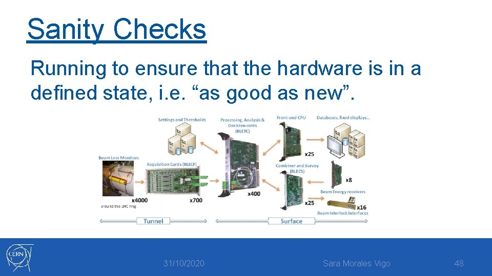
Sanity Checks Running to ensure that the hardware is in a defined state, i. e. “as good as new”. 31/10/2020 Sara Morales Vigo 48
Sanity Checks In case of a detected non-conformity: • The beam permit is not given back • No injections in the LHC can be performed 31/10/2020 Sara Morales Vigo 49
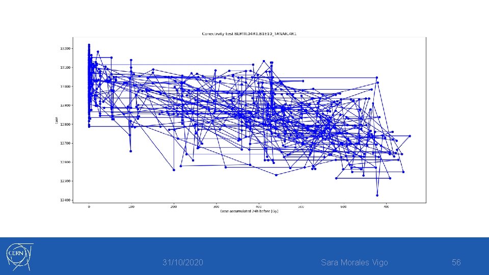
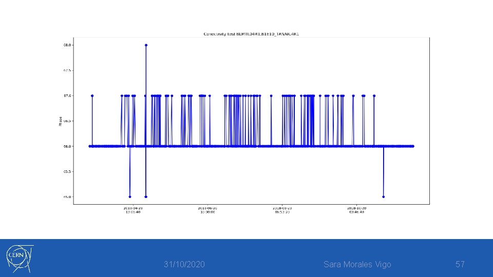
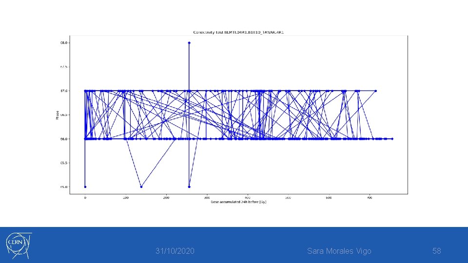
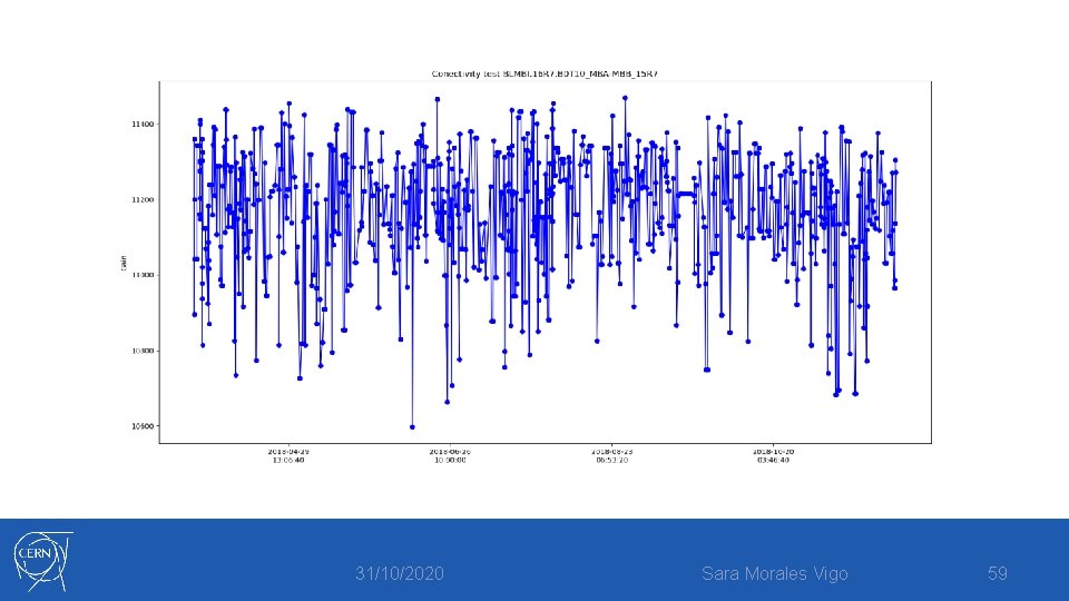
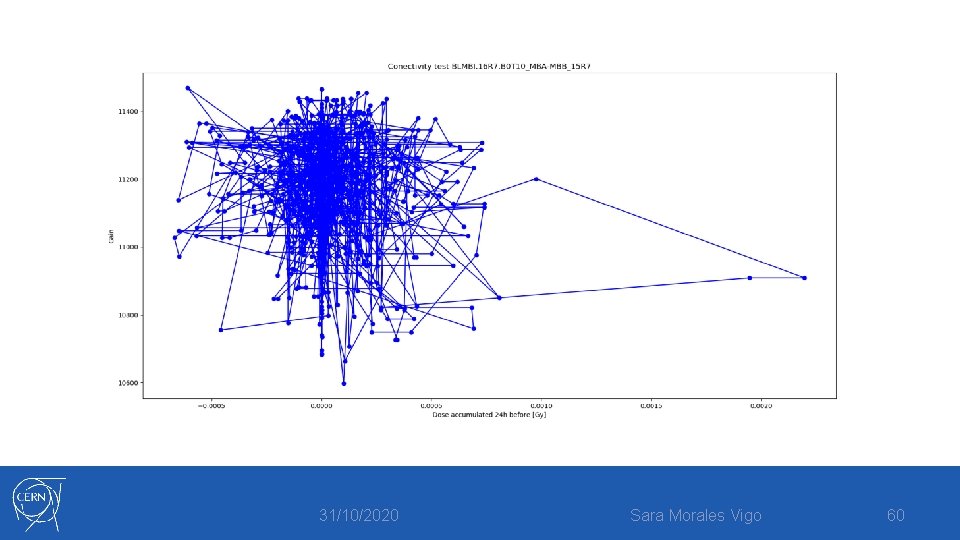
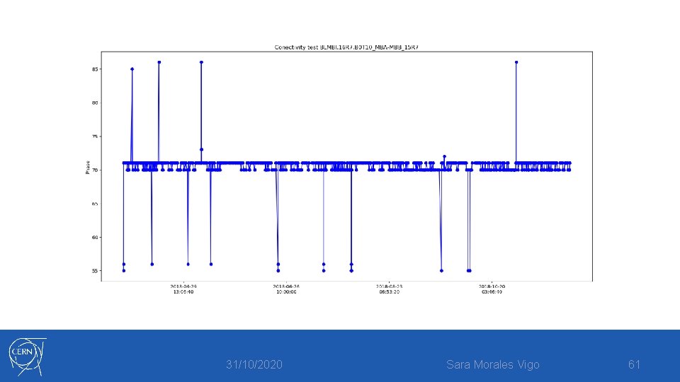
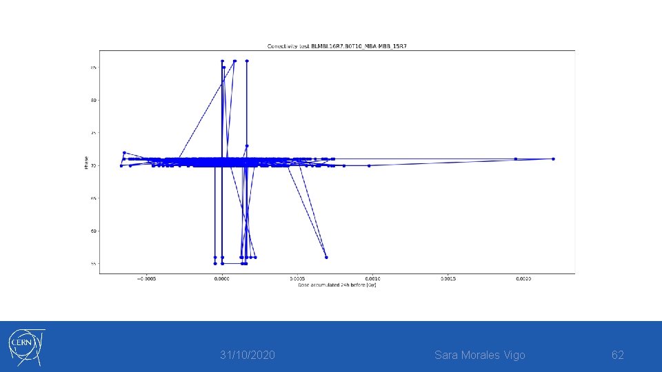
Connectivity check Primary purpose -> Ensure the integrity of the cabling of each beam loss detector. • How? 31/10/2020 Sara Morales Vigo 50
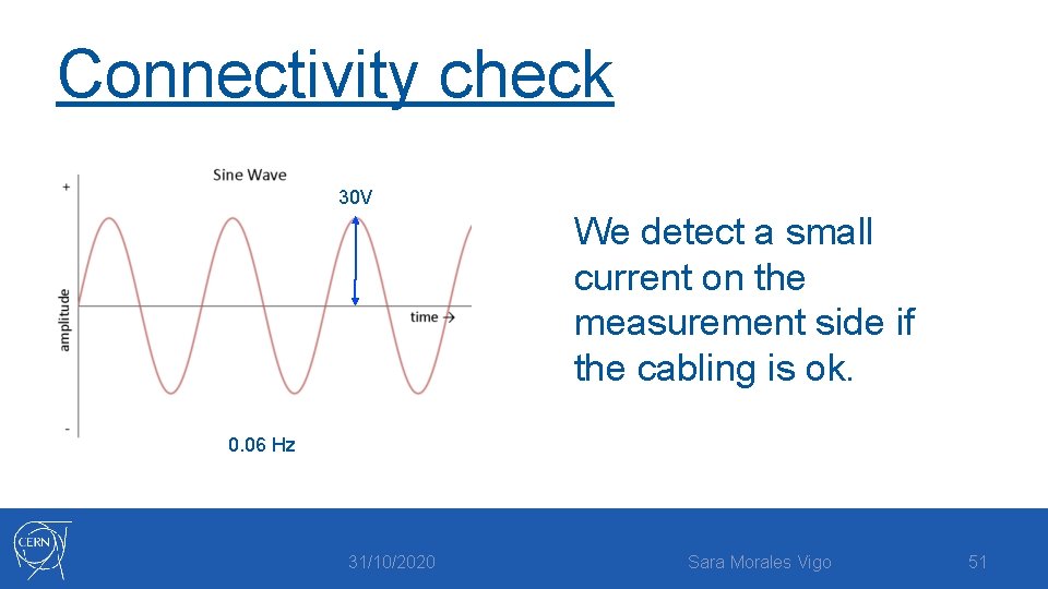
Connectivity check 30 V We detect a small current on the measurement side if the cabling is ok. 0. 06 Hz 31/10/2020 Sara Morales Vigo 51
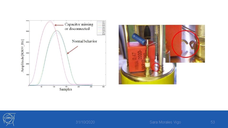
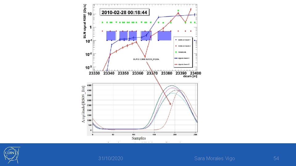
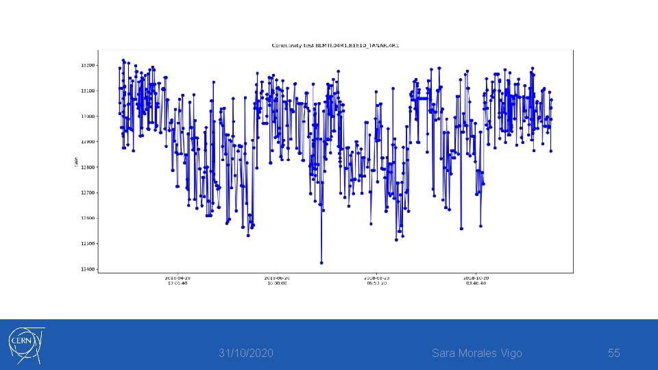
Connectivity check The second goal -> Survey the integrity of the components: • The measured amplitude and phase of every channel -> compared to a predefined threshold measured for every channel. • If one of them is outside the limits, the beam will not be permitted in the LHC. 31/10/2020 Sara Morales Vigo 52
31/10/2020 Sara Morales Vigo 53
31/10/2020 Sara Morales Vigo 54
31/10/2020 Sara Morales Vigo 55
31/10/2020 Sara Morales Vigo 56
31/10/2020 Sara Morales Vigo 57
31/10/2020 Sara Morales Vigo 58
31/10/2020 Sara Morales Vigo 59
31/10/2020 Sara Morales Vigo 60
31/10/2020 Sara Morales Vigo 61
31/10/2020 Sara Morales Vigo 62
Thank you for your attention 31/10/2020 Sara Morales Vigo 63
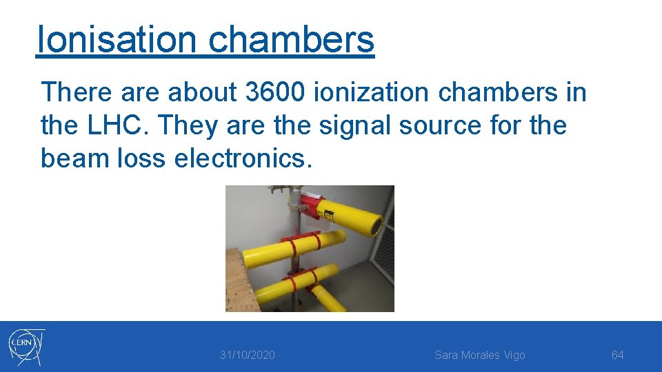
Ionisation chambers There about 3600 ionization chambers in the LHC. They are the signal source for the beam loss electronics. 31/10/2020 Sara Morales Vigo 64
31/10/2020 Sara Morales Vigo 65
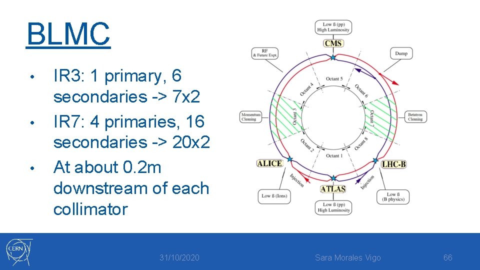
BLMC • • • IR 3: 1 primary, 6 secondaries -> 7 x 2 IR 7: 4 primaries, 16 secondaries -> 20 x 2 At about 0. 2 m downstream of each collimator 31/10/2020 Sara Morales Vigo 66
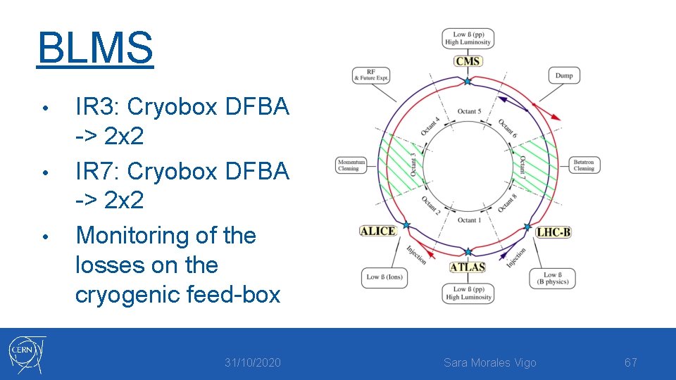
BLMS • • • IR 3: Cryobox DFBA -> 2 x 2 IR 7: Cryobox DFBA -> 2 x 2 Monitoring of the losses on the cryogenic feed-box 31/10/2020 Sara Morales Vigo 67
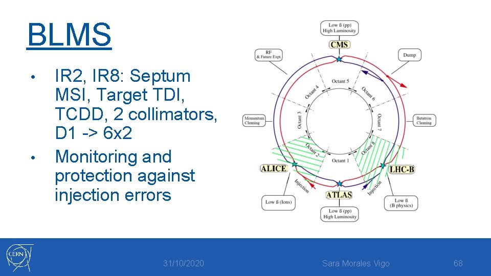
BLMS • • IR 2, IR 8: Septum MSI, Target TDI, TCDD, 2 collimators, D 1 -> 6 x 2 Monitoring and protection against injection errors 31/10/2020 Sara Morales Vigo 68
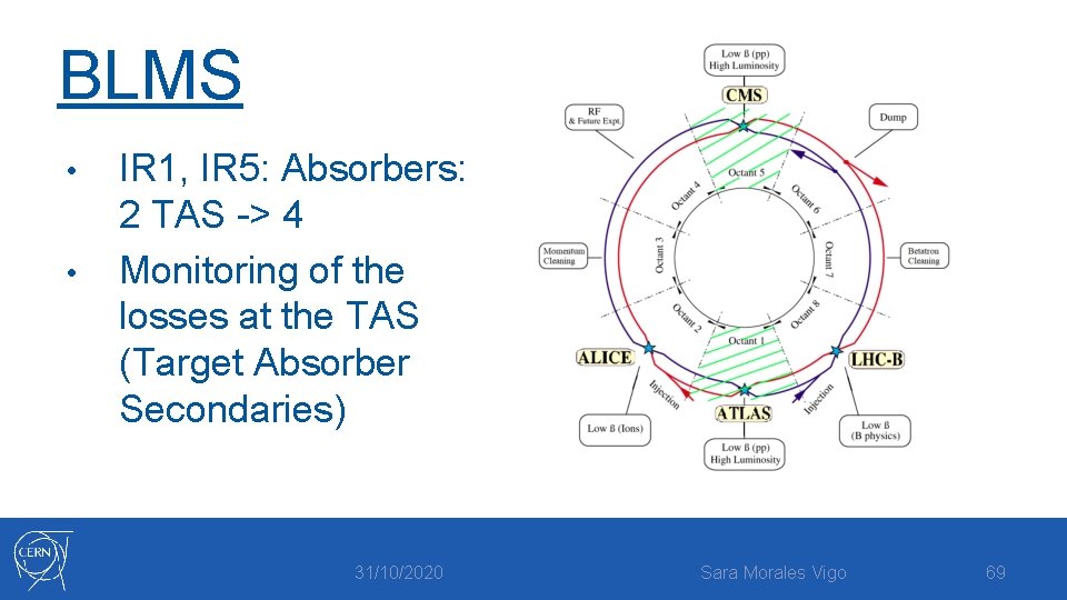
BLMS • • IR 1, IR 5: Absorbers: 2 TAS -> 4 Monitoring of the losses at the TAS (Target Absorber Secondaries) 31/10/2020 Sara Morales Vigo 69
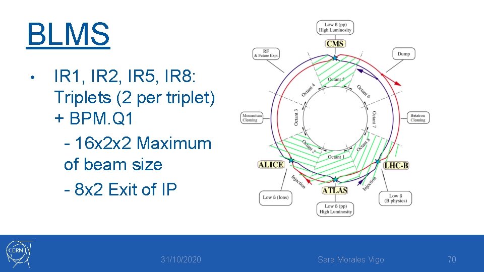
BLMS • IR 1, IR 2, IR 5, IR 8: Triplets (2 per triplet) + BPM. Q 1 - 16 x 2 x 2 Maximum of beam size - 8 x 2 Exit of IP 31/10/2020 Sara Morales Vigo 70
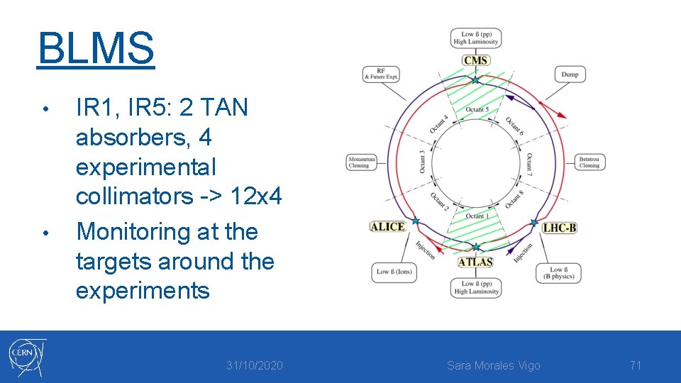
BLMS • • IR 1, IR 5: 2 TAN absorbers, 4 experimental collimators -> 12 x 4 Monitoring at the targets around the experiments 31/10/2020 Sara Morales Vigo 71
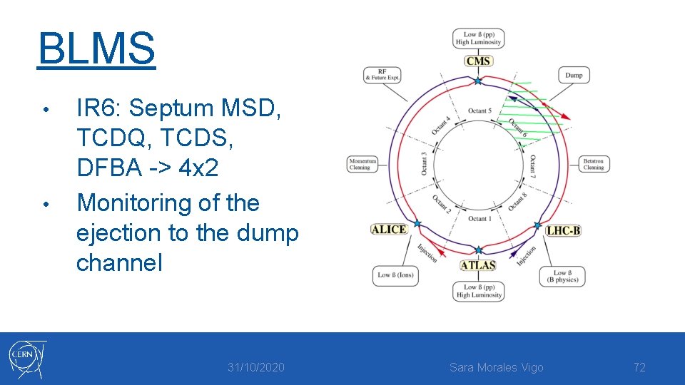
BLMS • • IR 6: Septum MSD, TCDQ, TCDS, DFBA -> 4 x 2 Monitoring of the ejection to the dump channel 31/10/2020 Sara Morales Vigo 72
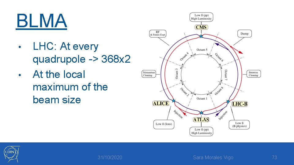
BLMA • • LHC: At every quadrupole -> 368 x 2 At the local maximum of the beam size 31/10/2020 Sara Morales Vigo 73
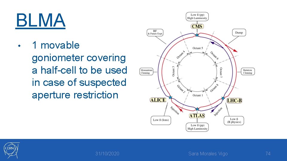
BLMA • 1 movable goniometer covering a half-cell to be used in case of suspected aperture restriction 31/10/2020 Sara Morales Vigo 74
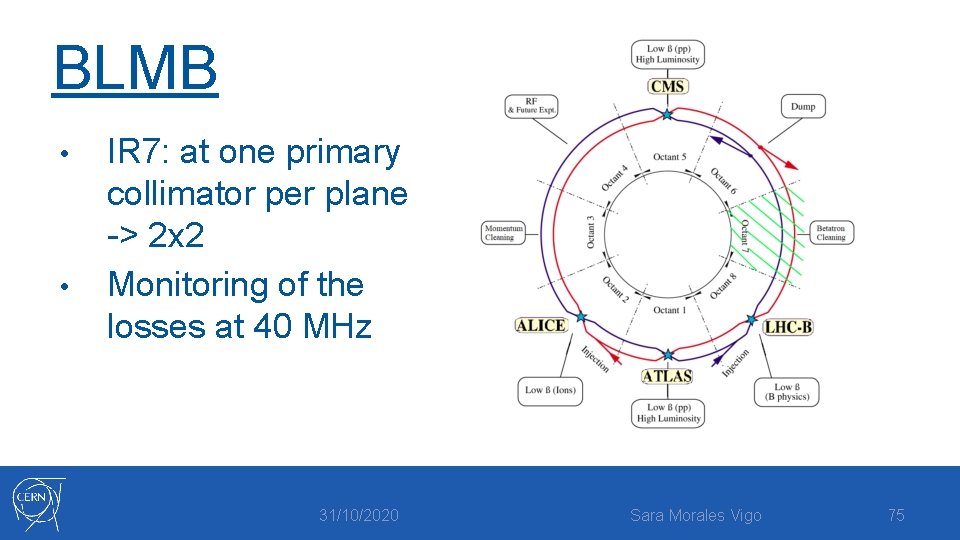
BLMB • • IR 7: at one primary collimator per plane -> 2 x 2 Monitoring of the losses at 40 MHz 31/10/2020 Sara Morales Vigo 75

Functional families of BLMC -> Collimation sections • BLMS -> Critical aperture limits or critical positions • BLMA -> All along the rings • BLMB -> Primary collimators • 31/10/2020 Sara Morales Vigo 76
- Slides: 76