Beam Gas Curtain BGC profile monitor Tom Dodington
 profile monitor Tom Dodington, Ray Veness BE-BI-ML 04/10/2018 Slides taken")
Beam Gas Curtain (BGC) profile monitor Tom Dodington, Ray Veness BE-BI-ML 04/10/2018 Slides taken from Ray Veness’s presentation at 37 th HL-LHC TCC: https: //indico. cern. ch/event/666310/contributions/2722985/
 • • Experience and experimental equipment for")
The BGC Collaboration The Cockcroft Institute (UK) • • Experience and experimental equipment for beam-gas curtains Part of the High-Lumi/UK framework collaboration (WP 3 -Beam diagnostics) which includes co-funding for researchers, an experimental programme and construction of 2 prototypes, including one adapted for testing in the LHC GSI (DE) • • Expertise in beam-induced fluorescence and monitoring Collaboration agreement for the BGC since 2016 funding senior researchers and providing optics for the Cockcroft set-up CERN • • • Instrument design, optics and integration expertise (BE-BI) Molecular gas flow simulation expertise (TE-VSC) Mechanical design and specialist production (EN-MME) Wroclow University of Science and Technology (PL) • • Expertise in computational fluid dynamics simulations for supersonic gas jets Collaboration under discussion 2

Beam-Gas Curtain Principles The light emitted from the BIF is imaged with an ex-vaccua optical system consisting of lens, image intensifier and CCD camera. Gas jet atoms or molecules are excited by beam interactions and emit photons (Beam Induced Florescence or ‘BIF’) Co-axial proton (blue) and electron (orange) beams in a hollow elens configuration Key parameters influencing BIF are beam intensities, gas jet density and thickness, beam -gas cross section. The cross section is a function of gas species, particle type and energy. In addition, a spectral range of different florescence transitions are excited depending on gas species Laminar, supersonic gas ‘curtain’ traverses the beams 3

V 1 Prototype Configuration 4

V 2 Prototype Configuration 5

V 2 Prototype 6

Experimental System and Results Prototype v 1 beam-gas curtain florescence monitor at the Cockcroft Institute 2017: Demonstration of beam-induced florescence with a N 2 gas jet • 10 u. A / 5 ke. V electron beam • Integration times are long due to low e-beam intensity (>1000 s) • Estimated ~2. 5 x 10⁵ photons/s for a 5 A electron beam and expected N 2 gas curtain and proposed optical system Now in progress: • Integration of a new electron gun reaching upto 300 u. A / 10 ke. V • Tests with a Ne gas jet with a new, optimized optical system • Production of second gas jet prototype (Version 2) Image of fluorescence from a gas jet curtain interaction with 3. 5 ke. V e- beam at the Cockcroft Institute (S. Udrea et al. IBIC 2017) 7

Florescence cross-sections Proton excitation florescence cross-section for a specific N 2 transition, extrapolated to 7 Te. V (green dot) Electron excitation florescence cross-section for a specific N 2 transition, extrapolated to 10 ke. V (green dot) Electron excitation florescence cross-section for a specific Ne transition, extrapolated to 10 ke. V (green dot) Currently evaluating N 2 and Ne for jet gas Ne has advantages for LHC • • • Observed transition is neutral excitation (not ionization), so no beam charge movement effects Shorter excitation decay time (~15 ns), so improved spatial resolution Not pumped by NEG coatings, so preferred by vacuum Data for proton cross-sections only available up to 450 Ge. V (SPS) for N 2 and 1 Me. V for Ne Data courtesy S. Udrea/GSI 8

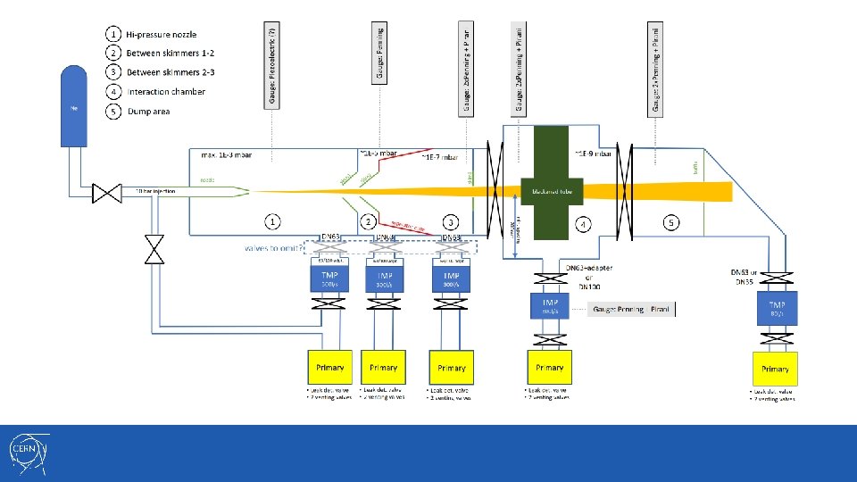
V 3 LHC Integration Gas exhaust system and diagnostics Gas jet generator, consisting of gas bottle, high-pressure nozzle, molecular flow skimmers and vacuum pumps Beam-gas interaction chamber, with gate valves to isolate beam vacuum from other components (in blue) Optical acquisition system, separated from beam vacuum by a viewport


12
- Slides: 12