
Beam dynamics and linac optics studies for medical
Beam dynamics and linac optics studies for medical proton accelerators R. Apsimon, G. Burt, S. Pitman Lancaster University / Cockcroft Institute H. Owen Manchester University / Cockcroft Institute
Overview • Brief introduction to cyclinacs • Beam dynamics – Transmission through a cavity – Optimisation of beam parameters • Linac optics – Spatial considerations – Quadrupole considerations
Brief introduction to cyclinacs I • Cyclotron protons accelerated through linac – Allows final beam energy to be varied – Allows treatment and imaging in single machine • ~250 Me. V protons for treatment • ~350 Me. V protons for imaging • Due to Bragg peak, protons deposit most of their energy in a very small range – Minimises dose to healthy tissue – Ideal for cancer treatment
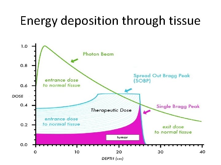
Energy deposition through tissue
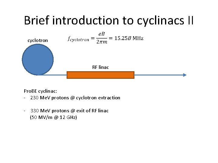
Brief introduction to cyclinacs II cyclotron RF linac Pro. BE cyclinac: - 230 Me. V protons @ cyclotron extraction - 330 Me. V protons @ exit of RF linac (50 MV/m @ 12 GHz)
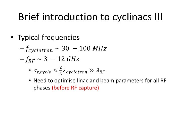
Brief introduction to cyclinacs III •
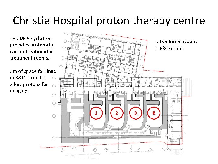
Christie Hospital proton therapy centre 230 Me. V cyclotron provides protons for cancer treatment in treatment rooms. 3 treatment rooms 1 R&D room 3 m of space for linac in R&D room to allow protons for imaging 1 2 3 R
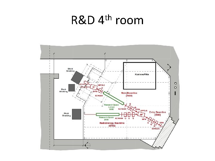
R&D 4 th room
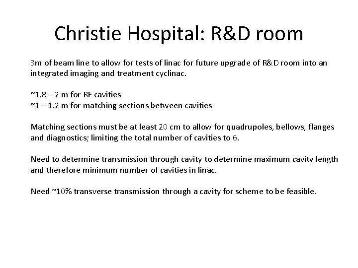
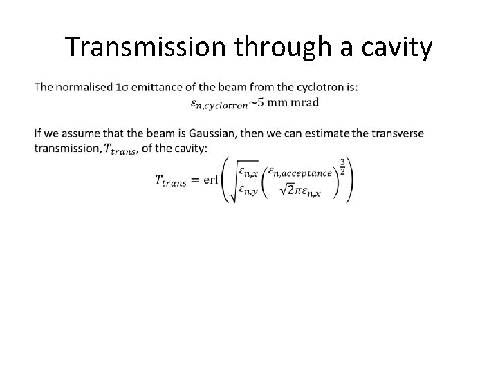
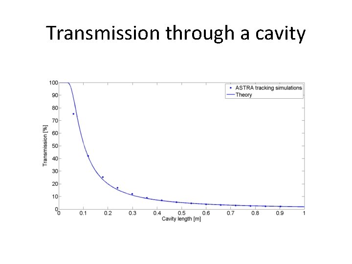
Christie Hospital: R&D room 3 m of beam line to allow for tests of linac for future upgrade of R&D room into an integrated imaging and treatment cyclinac. ~1. 8 – 2 m for RF cavities ~1 – 1. 2 m for matching sections between cavities Matching sections must be at least 20 cm to allow for quadrupoles, bellows, flanges and diagnostics; limiting the total number of cavities to 6. Need to determine transmission through cavity to determine maximum cavity length and therefore minimum number of cavities in linac. Need ~10% transverse transmission through a cavity for scheme to be feasible.
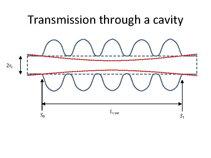
Transmission through a cavity
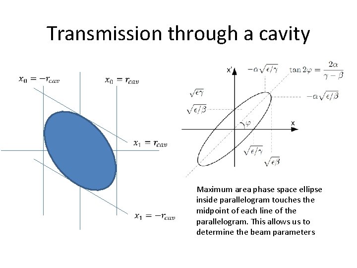
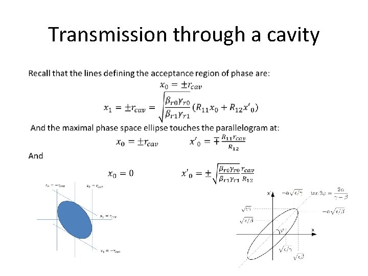
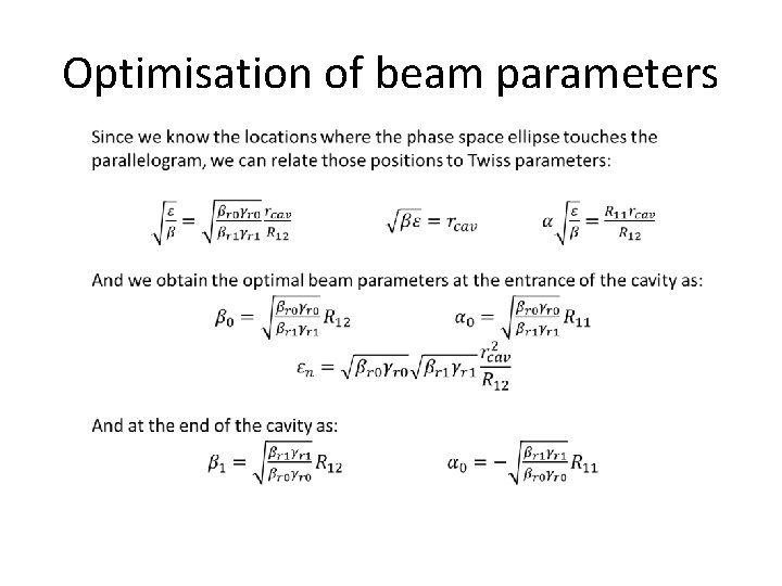
Transmission through a cavity Maximum area phase space ellipse inside parallelogram touches the midpoint of each line of the parallelogram. This allows us to determine the beam parameters
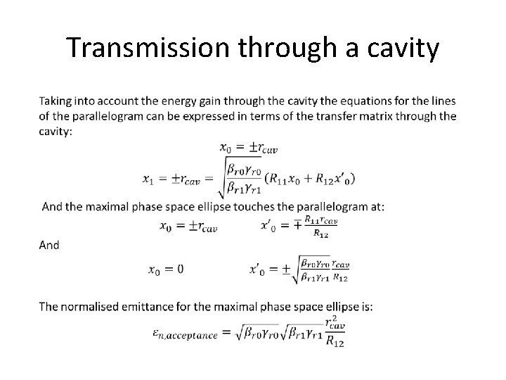
Transmission through a cavity
Transmission through a cavity
Transmission through a cavity
Transmission through a cavity
Optimisation of beam parameters

Optimisation of beam parameters
Linac optics Maximise transmission: • Need to match beam parameters through each cavity • Need quadrupole matching section Medical proton accelerators must be as compact as possible • Need to minimise length of matching sections • Maximise accelerating gradient of cavities
Quadrupole considerations Each matching section ~24 cm Need strong quadrupole fields (250 – 400 m-2) to match optics in such small space: • Permanent magnet quadrupole • Small aperture electromagnetic quadrupoles Quadrupole length: 3 – 3. 5 cm Bore radius: 1. 5 – 2. 5 mm Drifts between quads: ~2 – 6 cm Need minimum of ~ 2 cm for bellows, flanges etc.
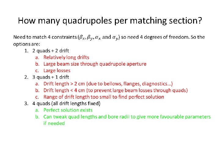
How many quadrupoles per matching section?
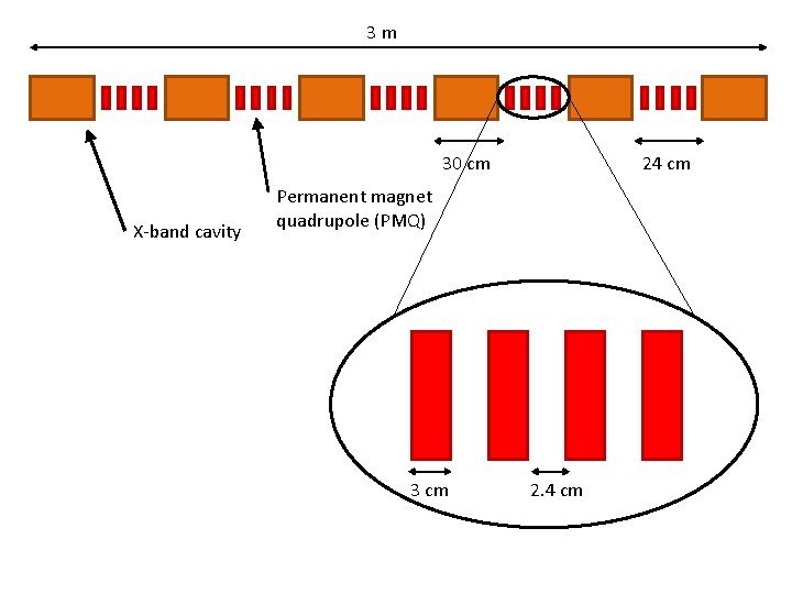
3 m 30 cm X-band cavity 24 cm Permanent magnet quadrupole (PMQ) 3 cm 2. 4 cm
Conclusions Studies of transverse beam dynamics through cavities have been undertaken: • Maximum transverse transmission through a cavity determined • Verified against tracking simulations • Determined optimal beam parameters through cavity to give maximum transverse transmission Matching sections designed to match beam parameters between cavities within the spatial limits. Still to do: • Study beam dynamics through full linac structure • Only single cavities investigated so far • Verify transmission studies for short bunches • Design matching sections for entire linac structure
- Slides: 22