
Beam Diagnostics Instruments Uli Raich CERN BE BI
Beam Diagnostics Instruments Uli Raich CERN BE - BI (Beam Instrumentation) Kigali, Rwanda 2016
Overview • • First part: – Introduction – Overview of measurement instruments • TV Screens • Scintillating screens • Faraday Cup • Beam Current Transformer • Beam Position Monitor • Profile Detectors – SEMGrids – Wire Scanners • Beam Loss Monitors Second part – Some depicted examples of beam parameter measurements Kigali, Rwanda 2016 2
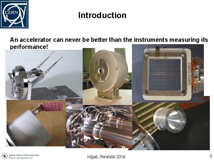
Introduction An accelerator can never be better than the instruments measuring its performance! Kigali, Rwanda 2016 3
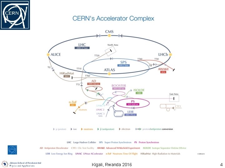
Kigali, Rwanda 2016 4
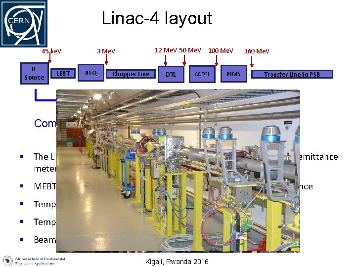
Linac-4 layout HSource LEBT 12 Me. V 50 Me. V 100 Me. V 3 Me. V 45 ke. V RFQ Chopper Line DTL CCDTL PIMS 160 Me. V Transfer Line to PSB Commissioned up to 100 Me. V (CCDTL) § The LEBT instrumentation is temporarily extended with a slit/grid emittance meter § MEBT line transformer and wire scanners show chopper performance § Temporary 3/12 Me. V measurement line § Temporary 50/100 Me. V measurement line § Beam characterization with operational diagnostics at 160 Me. V Kigali, Rwanda 2016
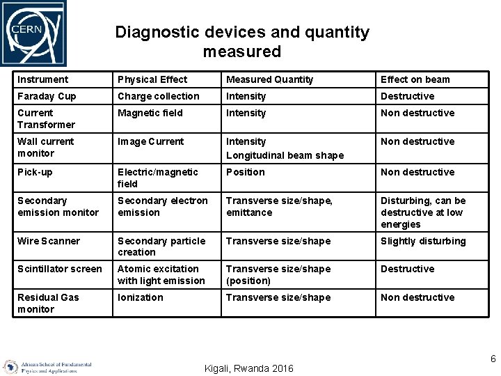
Diagnostic devices and quantity measured Instrument Physical Effect Measured Quantity Effect on beam Faraday Cup Charge collection Intensity Destructive Current Transformer Magnetic field Intensity Non destructive Wall current monitor Image Current Intensity Longitudinal beam shape Non destructive Pick-up Electric/magnetic field Position Non destructive Secondary emission monitor Secondary electron emission Transverse size/shape, emittance Disturbing, can be destructive at low energies Wire Scanner Secondary particle creation Transverse size/shape Slightly disturbing Scintillator screen Atomic excitation with light emission Transverse size/shape (position) Destructive Residual Gas monitor Ionization Transverse size/shape Non destructive Kigali, Rwanda 2016 6
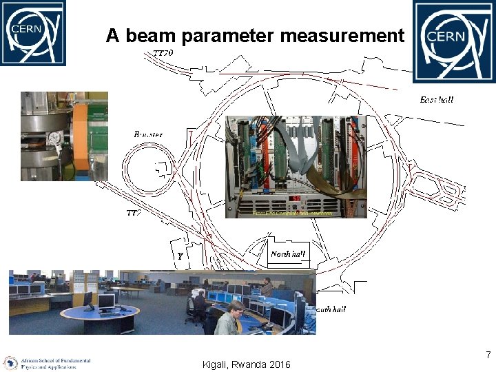
A beam parameter measurement Kigali, Rwanda 2016 7
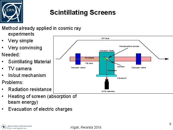
Scintillating Screens Method already applied in cosmic ray experiments • Very simple • Very convincing Needed: • Scintillating Material • TV camera • In/out mechanism Problems: • Radiation resistance of TV camera • Heating of screen (absorption of beam energy) • Evacuation of electric charges Kigali, Rwanda 2016 8
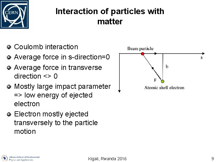
Interaction of particles with matter Coulomb interaction Average force in s-direction=0 Average force in transverse direction <> 0 Mostly large impact parameter => low energy of ejected electron Electron mostly ejected transversely to the particle motion Kigali, Rwanda 2016 9
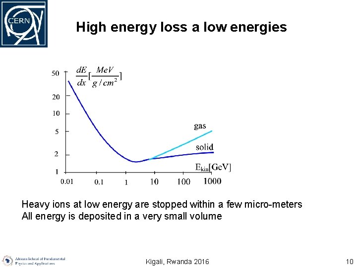
High energy loss a low energies Heavy ions at low energy are stopped within a few micro-meters All energy is deposited in a very small volume Kigali, Rwanda 2016 10
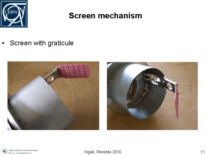
Screen mechanism • Screen with graticule Kigali, Rwanda 2016 11
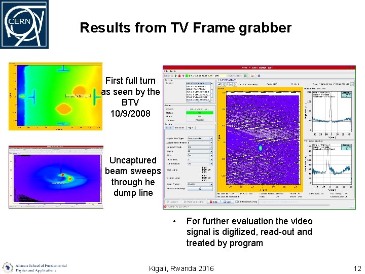
Results from TV Frame grabber First full turn as seen by the BTV 10/9/2008 Uncaptured beam sweeps through he dump line • For further evaluation the video signal is digitized, read-out and treated by program Kigali, Rwanda 2016 12
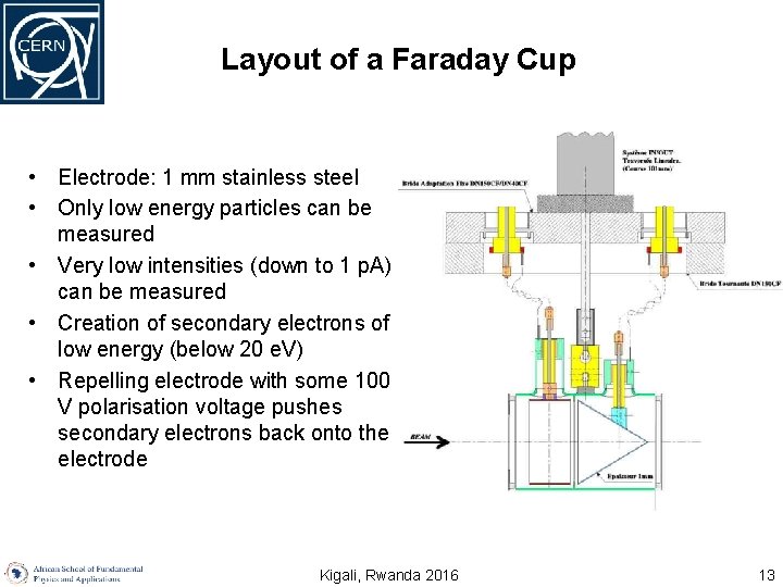
Layout of a Faraday Cup • Electrode: 1 mm stainless steel • Only low energy particles can be measured • Very low intensities (down to 1 p. A) can be measured • Creation of secondary electrons of low energy (below 20 e. V) • Repelling electrode with some 100 V polarisation voltage pushes secondary electrons back onto the electrode Kigali, Rwanda 2016 13
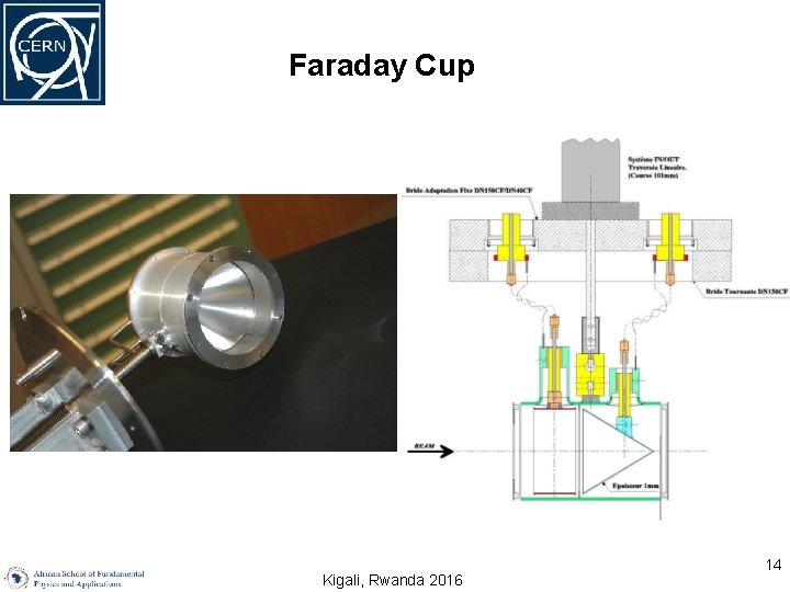
Faraday Cup Kigali, Rwanda 2016 14
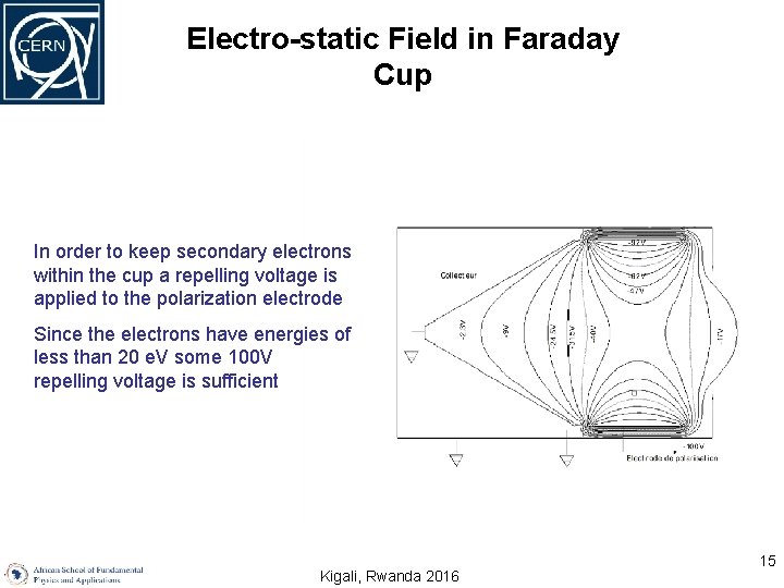
Electro-static Field in Faraday Cup In order to keep secondary electrons within the cup a repelling voltage is applied to the polarization electrode Since the electrons have energies of less than 20 e. V some 100 V repelling voltage is sufficient Kigali, Rwanda 2016 15
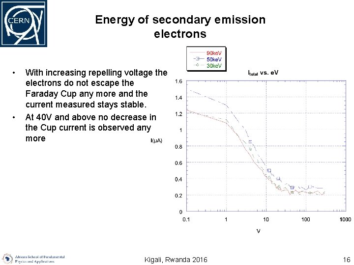
Energy of secondary emission electrons • • With increasing repelling voltage the electrons do not escape the Faraday Cup any more and the current measured stays stable. At 40 V and above no decrease in the Cup current is observed any more Kigali, Rwanda 2016 16
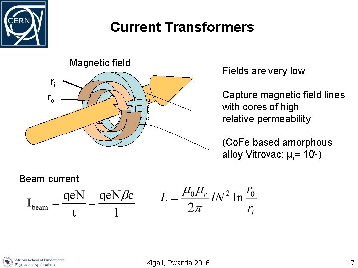
Current Transformers Magnetic field Fields are very low ri Capture magnetic field lines with cores of high relative permeability ro (Co. Fe based amorphous alloy Vitrovac: μr= 105) Beam current Kigali, Rwanda 2016 17
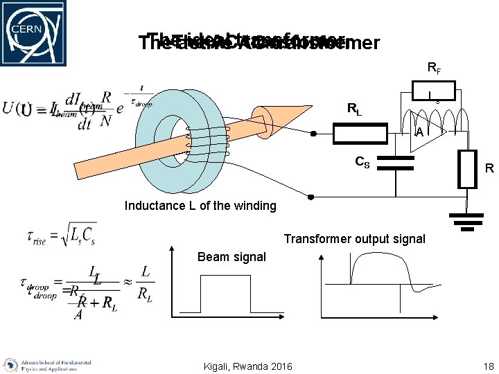
The ideal The ACtransformer The active AC transformer RF Ls RLL A CSS R Inductance L of the winding Transformer output signal Beam signal Kigali, Rwanda 2016 18
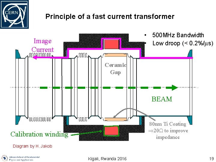
Principle of a fast current transformer • 500 MHz Bandwidth • Low droop (< 0. 2%/ s) Image Current Ceramic Gap BEAM 80 nm Ti Coating Þ 20 W to improve impedance Calibration winding Diagram by H. Jakob Kigali, Rwanda 2016 19
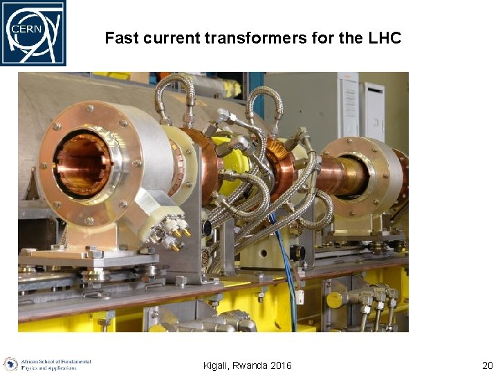
Fast current transformers for the LHC U. Raich CERN BE/BI African School on Fundamental Physics Kigali, Rwanda 2016 20
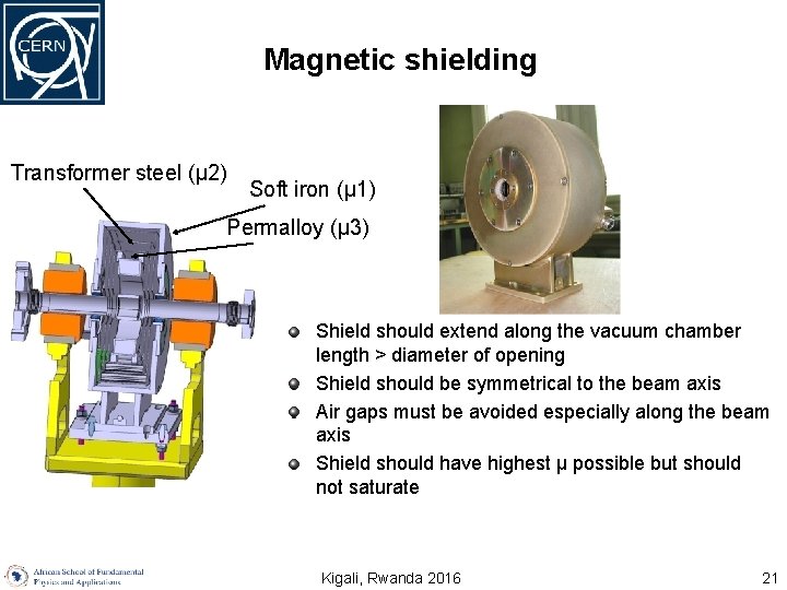
Magnetic shielding Transformer steel (μ 2) Soft iron (μ 1) Permalloy (μ 3) Shield should extend along the vacuum chamber length > diameter of opening Shield should be symmetrical to the beam axis Air gaps must be avoided especially along the beam axis Shield should have highest μ possible but should not saturate Kigali, Rwanda 2016 21
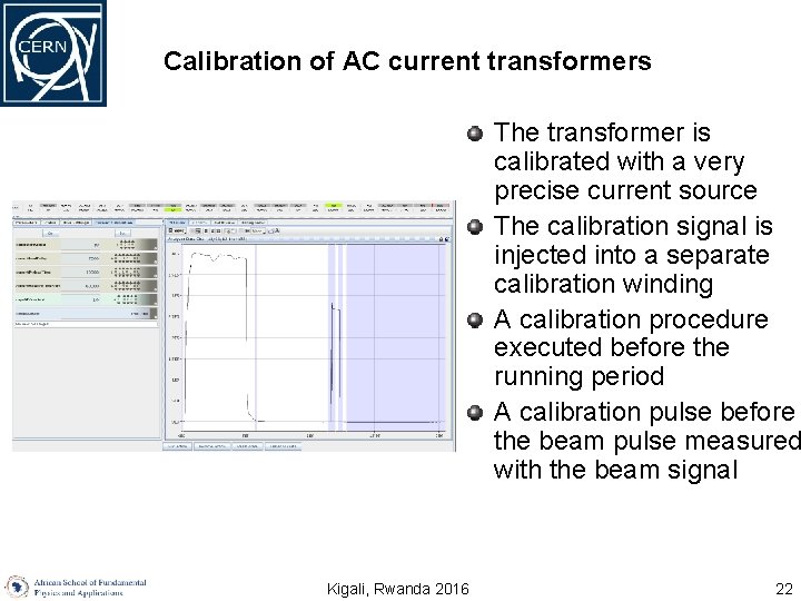
Calibration of AC current transformers The transformer is calibrated with a very precise current source The calibration signal is injected into a separate calibration winding A calibration procedure executed before the running period A calibration pulse before the beam pulse measured with the beam signal Kigali, Rwanda 2016 22
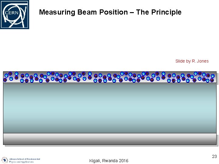
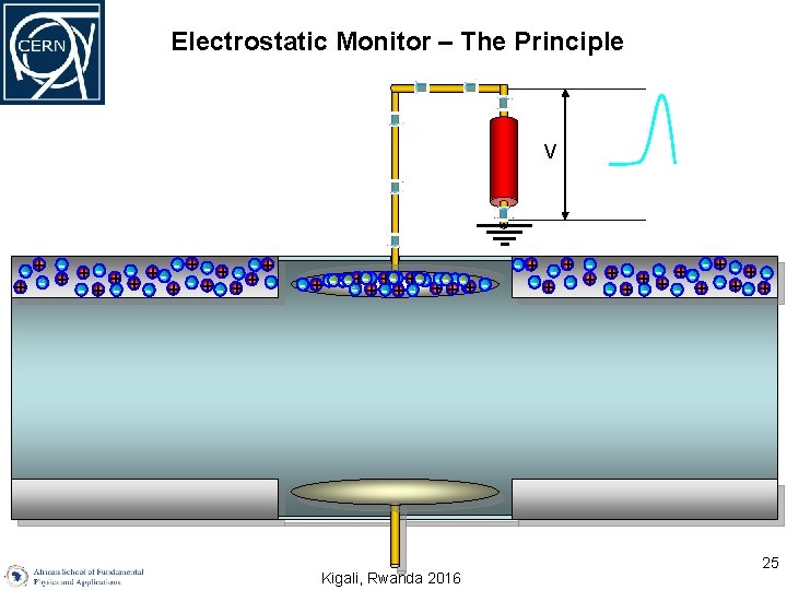
Measuring Beam Position – The Principle Slide by R. Jones - + +- + - + - + - +- + - + - + + - + - +- + -+ - + - +- + -+ - Kigali, Rwanda 2016 23
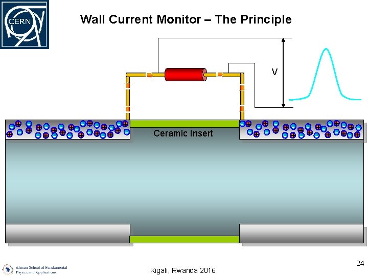
Wall Current Monitor – The Principle V - + +- + - +- + + - + - +- + - Ceramic Insert Kigali, Rwanda 2016 -+ -+ - - + - + - + +- + - -+ - + 24
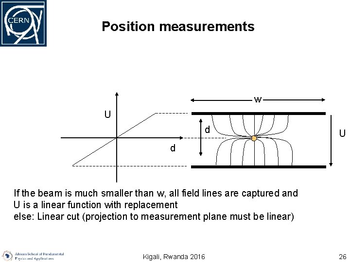
Position measurements w U d If the beam is much smaller than w, all field lines are captured and U is a linear function with replacement else: Linear cut (projection to measurement plane must be linear) Kigali, Rwanda 2016 26
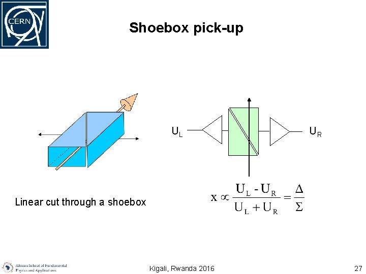
Shoebox pick-up UL UR Linear cut through a shoebox Kigali, Rwanda 2016 27
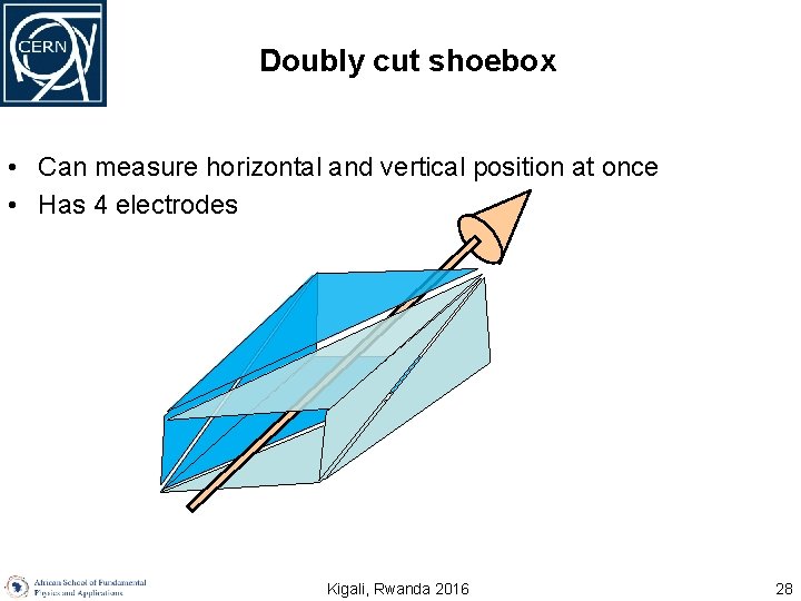
Doubly cut shoebox • Can measure horizontal and vertical position at once • Has 4 electrodes Kigali, Rwanda 2016 28
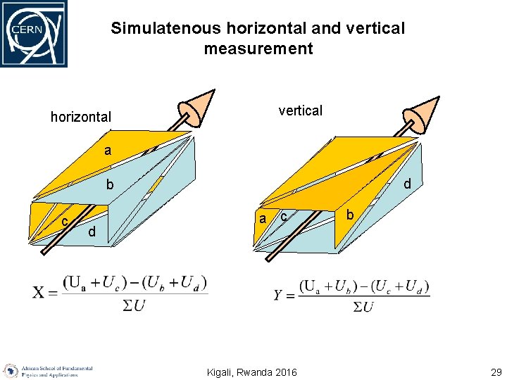
Simulatenous horizontal and vertical measurement horizontal vertical a b a c d d a a c Kigali, Rwanda 2016 b 29
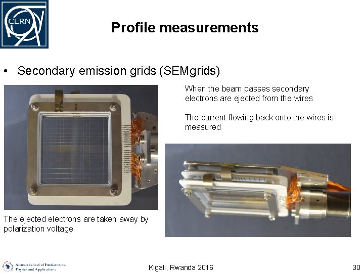
Profile measurements • Secondary emission grids (SEMgrids) When the beam passes secondary electrons are ejected from the wires The current flowing back onto the wires is measured The ejected electrons are taken away by polarization voltage Kigali, Rwanda 2016 30
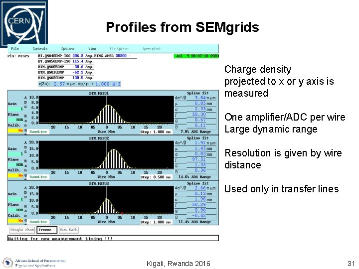
Profiles from SEMgrids Charge density projected to x or y axis is measured One amplifier/ADC per wire Large dynamic range Resolution is given by wire distance Used only in transfer lines U. Raich CERN BE/BI African School on Fundamental Physics Kigali, Rwanda 2016 31
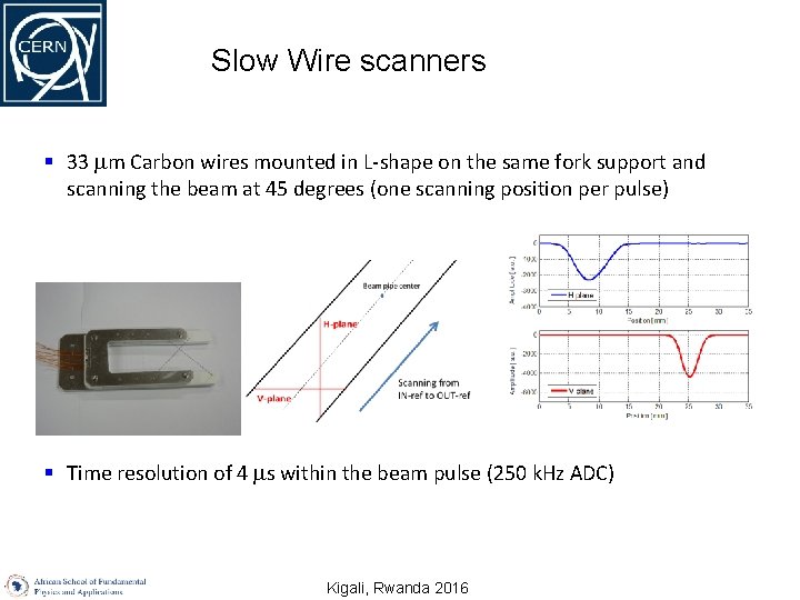
Slow Wire scanners § 33 m Carbon wires mounted in L-shape on the same fork support and scanning the beam at 45 degrees (one scanning position per pulse) § Time resolution of 4 s within the beam pulse (250 k. Hz ADC) Kigali, Rwanda 2016
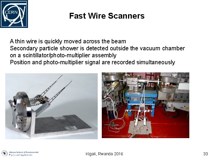
Fast Wire Scanners A thin wire is quickly moved across the beam Secondary particle shower is detected outside the vacuum chamber on a scintillator/photo-multiplier assembly Position and photo-multiplier signal are recorded simultaneously U. Raich CERN BE/BI African School on Fundamental Physics Kigali, Rwanda 2016 33
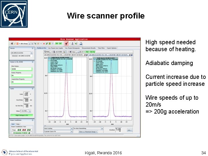
Wire scanner profile High speed needed because of heating. Adiabatic damping Current increase due to particle speed increase Wire speeds of up to 20 m/s => 200 g acceleration U. Raich CERN BE/BI African School on Fundamental Physics Kigali, Rwanda 2016 34
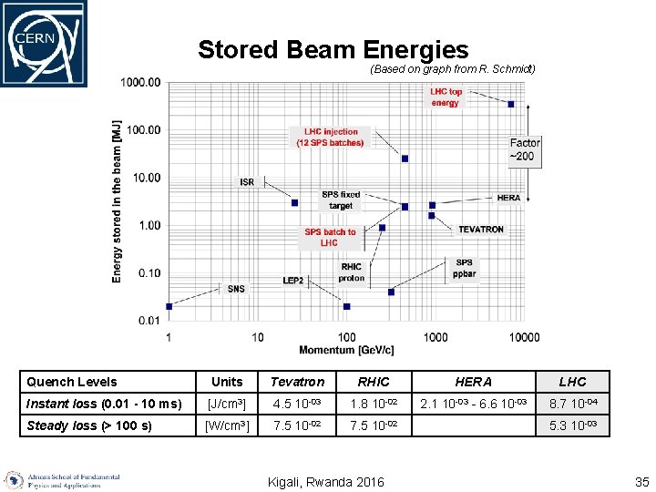
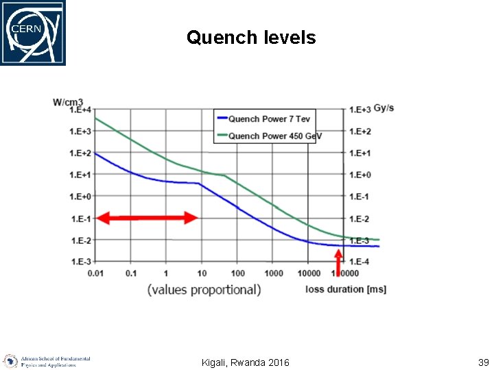
Stored Beam Energies (Based on graph from R. Schmidt) Quench Levels Units Tevatron RHIC HERA LHC Instant loss (0. 01 - 10 ms) [J/cm 3] 4. 5 10 -03 1. 8 10 -02 2. 1 10 -03 - 6. 6 10 -03 8. 7 10 -04 Steady loss (> 100 s) [W/cm 3] 7. 5 10 -02 Kigali, Rwanda 2016 5. 3 10 -03 35
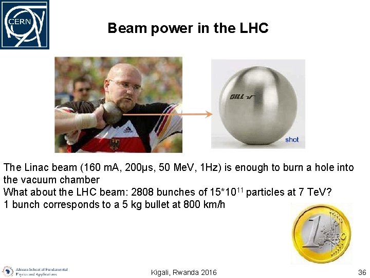
Beam power in the LHC The Linac beam (160 m. A, 200μs, 50 Me. V, 1 Hz) is enough to burn a hole into the vacuum chamber What about the LHC beam: 2808 bunches of 15*1011 particles at 7 Te. V? 1 bunch corresponds to a 5 kg bullet at 800 km/h Kigali, Rwanda 2016 36
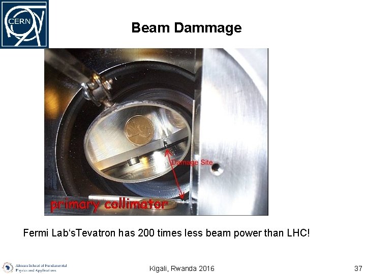
Beam Dammage Fermi Lab‘s. Tevatron has 200 times less beam power than LHC! Kigali, Rwanda 2016 37
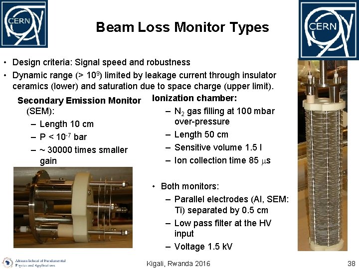
Beam Loss Monitor Types • Design criteria: Signal speed and robustness • Dynamic range (> 109) limited by leakage current through insulator ceramics (lower) and saturation due to space charge (upper limit). Secondary Emission Monitor Ionization chamber: – N 2 gas filling at 100 mbar (SEM): over-pressure – Length 10 cm – Length 50 cm – P < 10 -7 bar – Sensitive volume 1. 5 l – ~ 30000 times smaller – Ion collection time 85 s gain • Both monitors: – Parallel electrodes (Al, SEM: Ti) separated by 0. 5 cm – Low pass filter at the HV input – Voltage 1. 5 k. V Kigali, Rwanda 2016 38
Quench levels Kigali, Rwanda 2016 39
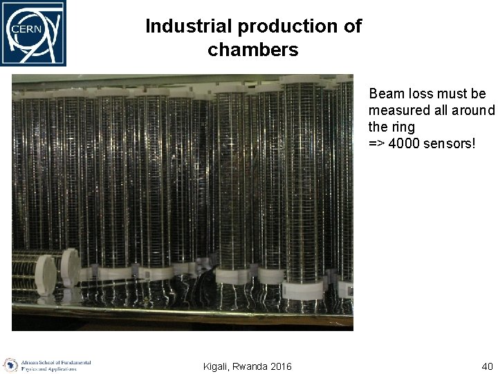
Industrial production of chambers Beam loss must be measured all around the ring => 4000 sensors! U. Raich CERN BE/BI African School on Fundamental Physics Kigali, Rwanda 2016 40
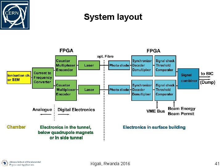
System layout Kigali, Rwanda 2016 41
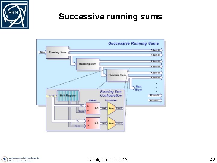
Successive running sums Kigali, Rwanda 2016 42
- Slides: 42