
BCM electronics status and plans BI forum Feb
BCM electronics: status and plans BI forum (Feb. 10 th and 11 th 2016) Hooman Hassanzadegan ESS, BI section 1
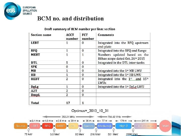
BCM no. and distribution Draft summary of BCM number per linac section 2

BCM requirements (general) 3
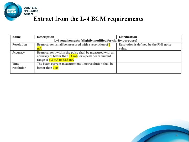
Extract from the L-4 BCM requirements 4
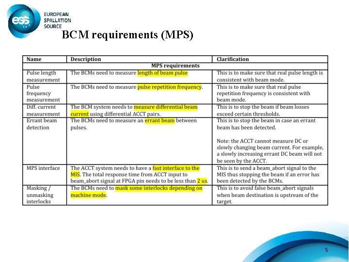
BCM requirements (MPS) 5
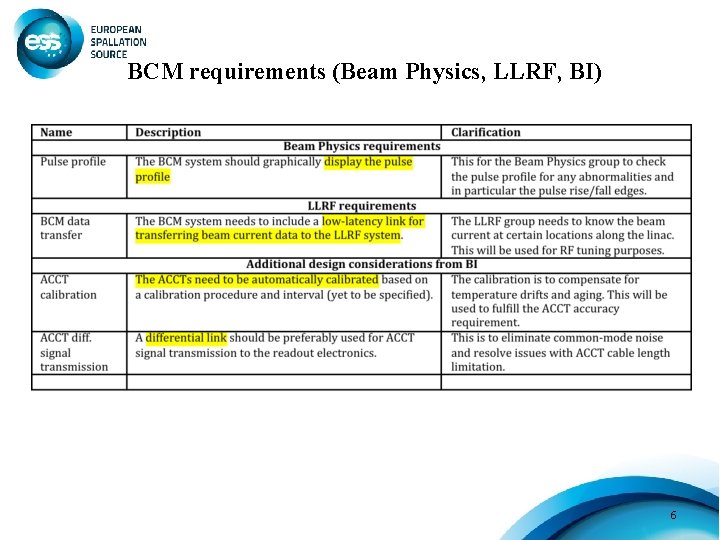
BCM requirements (Beam Physics, LLRF, BI) 6
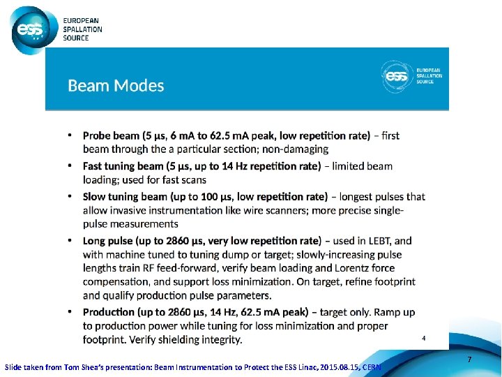
Slide taken from Tom Shea’s presentation: Beam Instrumentation to Protect the ESS Linac, 2015. 08. 15, CERN 7
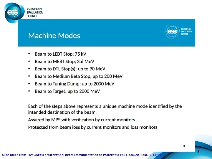
Slide taken from Tom Shea’s presentation: Beam Instrumentation to Protect the ESS Linac, 2015. 08. 15, CERN 8
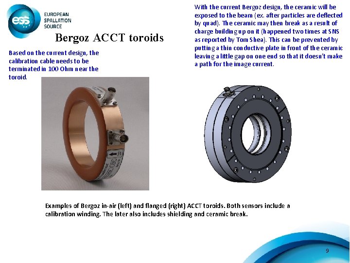
Bergoz ACCT toroids Based on the current design, the calibration cable needs to be terminated in 100 Ohm near the toroid. With the current Bergoz design, the ceramic will be exposed to the beam (ex. after particles are deflected by quad). The ceramic may then break as a result of charge building up on it (happened two times at SNS as reported by Tom Shea). This can be prevented by putting a thin conductive plate in front of the ceramic leaving a little gap on one end so that it doesn’t make a path for the image current. Examples of Bergoz in-air (left) and flanged (right) ACCT toroids. Both sensors include a calibration winding. The later also includes shielding and ceramic break. 9
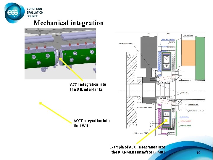
Mechanical integration ACCT integration into the DTL inter-tanks ACCT integration into the LWU Example of ACCT integration into the RFQ-MEBT interface (IFMIF) 10
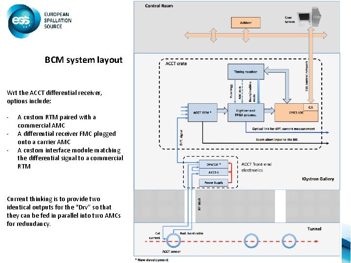
BCM system layout Wrt the ACCT differential receiver, options include: - A custom RTM paired with a commercial AMC A differential receiver FMC plugged onto a carrier AMC A custom interface module matching the differential signal to a commercial RTM Current thinking is to provide two identical outputs for the “Drv” so that they can be fed in parallel into two AMCs for redundancy. 11
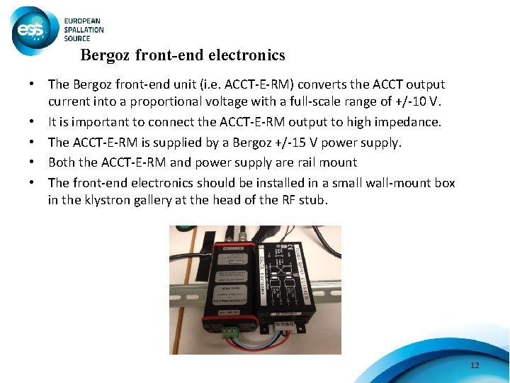
Bergoz front-end electronics • The Bergoz front-end unit (i. e. ACCT-E-RM) converts the ACCT output current into a proportional voltage with a full-scale range of +/-10 V. • It is important to connect the ACCT-E-RM output to high impedance. • The ACCT-E-RM is supplied by a Bergoz +/-15 V power supply. • Both the ACCT-E-RM and power supply are rail mount • The front-end electronics should be installed in a small wall-mount box in the klystron gallery at the head of the RF stub. 12
Drv/Cal module • The ACCT-E-RM output is fed into the Drv/Cal module that should sit next to the ACCT-E-RM and supplied by the same power supply. • The Drv/Cal module will then convert the single-ended output of the ACCT-E-RM to differential and feed this signal into a CAT-8 A cable that is terminated in 100 Ohm at both ends. • The Drv/Cal module will also generate a calibration current pulse out of the digital calibration pulse from the RTM. The Drv/Cal module will then convert this pulse to have a fixed current and feeds it into the ACCT calibration winding. • The Drv/Cal module will be a new development. Circuit schematics has been received form M. Werner (DESY) based on an ESS-DESY Mo. U and technical annex. 13
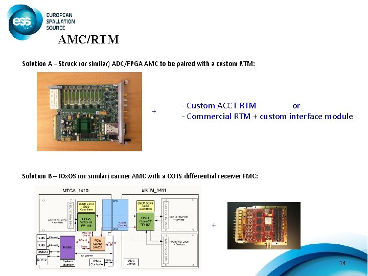
AMC/RTM Solution A – Struck (or similar) ADC/FPGA AMC to be paired with a custom RTM: + - Custom ACCT RTM or - Commercial RTM + custom interface module Solution B – IOx. OS (or similar) carrier AMC with a COTS differential receiver FMC: + 14
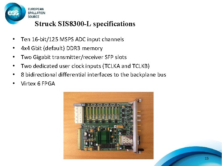
Struck SIS 8300 -L specifications • • • Ten 16 -bit/125 MSPS ADC input channels 4 x 4 Gbit (default) DDR 3 memory Two Gigabit transmitter/receiver SFP slots Two dedicated user clock inputs (TCLKA and TCLKB) 8 bidirectional differential interfaces to the backplane bus Virtex 6 FPGA 15
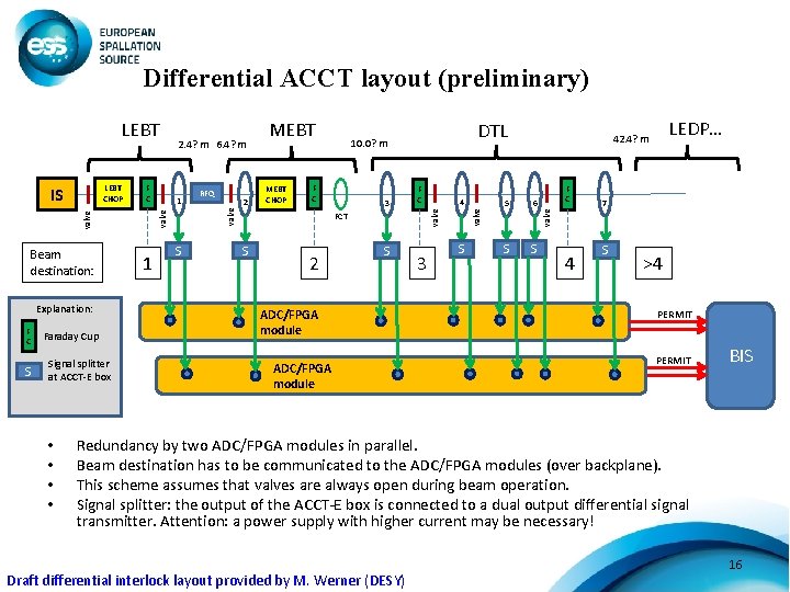
Differential ACCT layout (preliminary) Explanation: F C S Faraday Cup Signal splitter at ACCT-E box • • 1 S 2 MEBT CHOP DTL 10. 0? m F C 3 F C FCT S 2 4 S ADC/FPGA module 3 S LEDP… 42. 4? m 5 6 S S F C valve RFQ valve Beam destination: 1 MEBT valve F C valve LEBT CHOP IS 2. 4? m 6. 4? m valve LEBT 4 7 S >4 PERMIT BIS Redundancy by two ADC/FPGA modules in parallel. Beam destination has to be communicated to the ADC/FPGA modules (over backplane). This scheme assumes that valves are always open during beam operation. Signal splitter: the output of the ACCT-E box is connected to a dual output differential signal transmitter. Attention: a power supply with higher current may be necessary! Draft differential interlock layout provided by M. Werner (DESY) 16
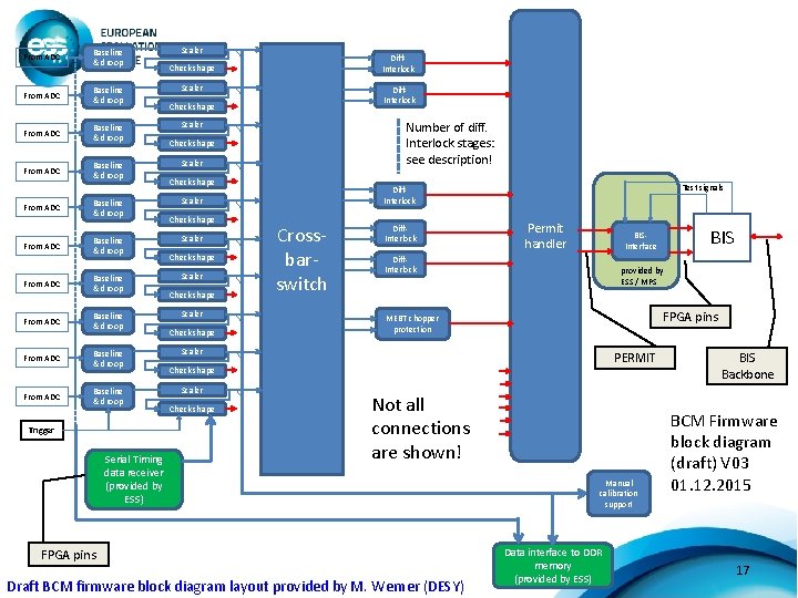
From ADC Baseline & droop From ADC Baseline & droop From ADC From ADC Baseline & droop Baseline & droop Trigger Serial Timing data receiver (provided by ESS) Scaler Diff. Interlock Check shape Number of diff. Interlock stages: see description! Scaler Check shape Scaler Check shape Test signals Diff. Interlock Scaler Crossbarswitch Diff. Interlock Permit handler Diff. Interlock provided by ESS / MPS FPGA pins MEBT chopper protection Scaler PERMIT Check shape Scaler Check shape Not all connections are shown! FPGA pins Draft BCM firmware block diagram layout provided by M. Werner (DESY) BISInterface Manual calibration support Data interface to DDR memory (provided by ESS) BIS Backbone BCM Firmware block diagram (draft) V 03 01. 12. 2015 17
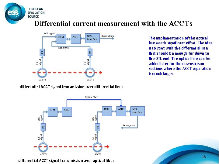
Differential current measurement with the ACCTs The implementation of the optical line needs significant effort. The idea is to start with the differential line that should be enough for down to the DTL end. The optical line can be added later for the downstream sections where the ACCT separation is much larger. differential ACCT signal transmission over differential lines differential ACCT signal transmission over optical fiber 18
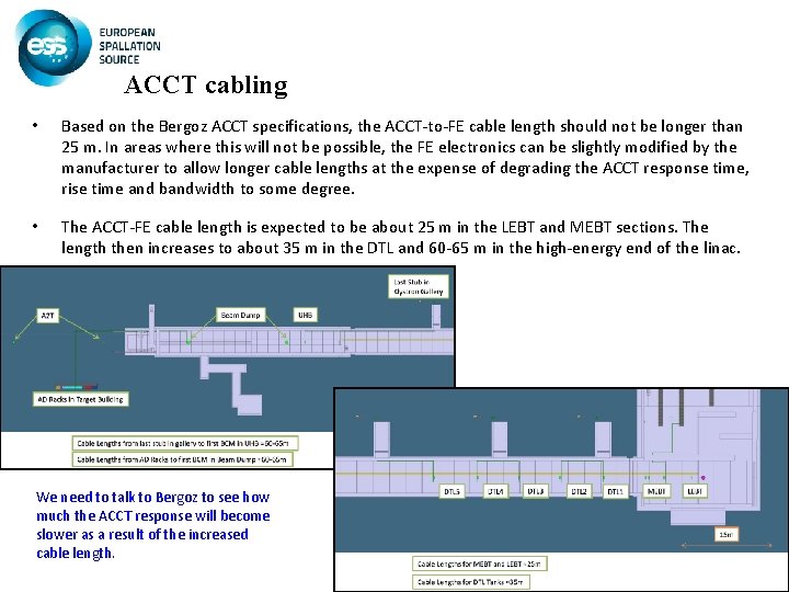
ACCT cabling • Based on the Bergoz ACCT specifications, the ACCT-to-FE cable length should not be longer than 25 m. In areas where this will not be possible, the FE electronics can be slightly modified by the manufacturer to allow longer cable lengths at the expense of degrading the ACCT response time, rise time and bandwidth to some degree. • The ACCT-FE cable length is expected to be about 25 m in the LEBT and MEBT sections. The length then increases to about 35 m in the DTL and 60 -65 m in the high-energy end of the linac. We need to talk to Bergoz to see how much the ACCT response will become slower as a result of the increased cable length. 19
Timing requirement for the electronics • Trigger/consistency check: Although the ACCT firmware will include a self-trigger mechanism that will trigger on the edge of the beam pulse, an external trigger will still be needed for the purpose of consistency check. The beam can then be stopped if the frequency of the trigger is not within the acceptable range, or if a beam pulse does not arrive shortly after each trigger. • Beam/machine mode data: The beam/machine mode data need to be transferred to the ACCT readout electronics using the timing system. The ACCT readout electronics will know the expected pulse current/width from the beam mode and the expected beam destination from the machine mode. This information will then be used to correctly configure the electronics including the width of the averaging filters and the masking/unmasking of some interlocks. • ADC clock: Although this is not strictly required, it is generally preferred that the ADC clock frequency be locked to RF. An external ADC clock of 88. 0525 MHz (¼ of the 352. 21 MHz RF frequency) can be provided by the timing receiver module and transferred to the ACCT AMC through a dedicated clock line of backplane. 20
LEBT ACCT plan (next 15 months) • An ACCT toroid should be delivered by Oct. 2016 to Catania-Italy for the ESS LEBT (type and size should be confirmed by Catania). • A pre-version of the LEBT ACCT firmware should to be developed and integrated into the generic Struck SIS 8300 -L firmware by the end of 2016. This pre-version will include MPS feature, but interfacing with the timing system and ACCT calibration is not foreseen for this version. • The commercial electronics, including the MTCA chassis, power supply, CPU, MCH, Struck SIS 8300 -L and RTM should be procured and integrated by Oct. 2016 -> this may be postponed to the end of 2016 to match the firmware delivery date. • Software development should go in parallel with the firmware and become available by the end of 2016. This effort can be minimized if an already-existing ACCT software could be modified and used for the new firmware. • Assuming a commercial RTM (ex. SIS 8900) will be used, a custom interface module should be provided to match the ACCT-E output to the RTM input. This can be a temporary solution until final boards become available. • Test with the ion source and LEBT is planned to start in mid-March 2017. 21

• Supporting slides… 22
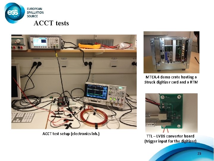
ACCT tests MTCA. 4 demo crate hosting a Struck digitizer card and a RTM ACCT test setup (electronics lab. ) TTL – LVDS converter board (trigger input for the digitizer) 23
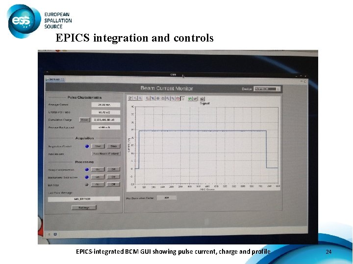
EPICS integration and controls EPICS-integrated BCM GUI showing pulse current, charge and profile 24
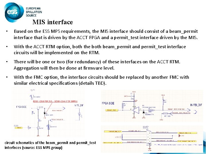
MIS interface • Based on the ESS MPS requirements, the MIS interface should consist of a beam_permit interface that is driven by the ACCT FPGA and a permit_test interface driven by the MIS. • With the ACCT RTM option, both the both beam_permit and permit_test interface circuits will be implemented on the RTM. • There will be one or two (for redundancy) of these interfaces on the ACCT RTM. Aggregation will then be done at firmware level. • With the FMC option, the interface circuits should be replaced by another FMC with similar electrical specifications (details TBD). circuit schematics of the beam_permit and permit_test interfaces (source: ESS MPS group) 25
- Slides: 25