
BCM BLM system requirements Hooman Hassanzadegan ESS Beam
BCM & BLM system requirements Hooman Hassanzadegan ESS, Beam Instrumentation Group 1
Outline 1. BCM system requirements 2. BCM connection to the MPS system 3. BLM requirements 4. BLM electronics 5. Summary 2
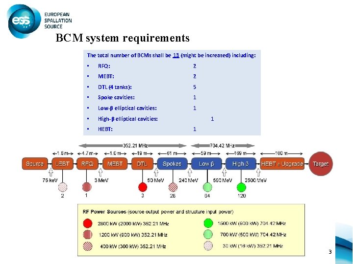
BCM system requirements The total number of BCMs shall be 13 (might be increased) including: • RFQ: 2 • MEBT: 2 • DTL (4 tanks): 5 • Spoke cavities: 1 • Low-β elliptical cavities: 1 • High-β elliptical cavities: • HEBT: 1 1 3
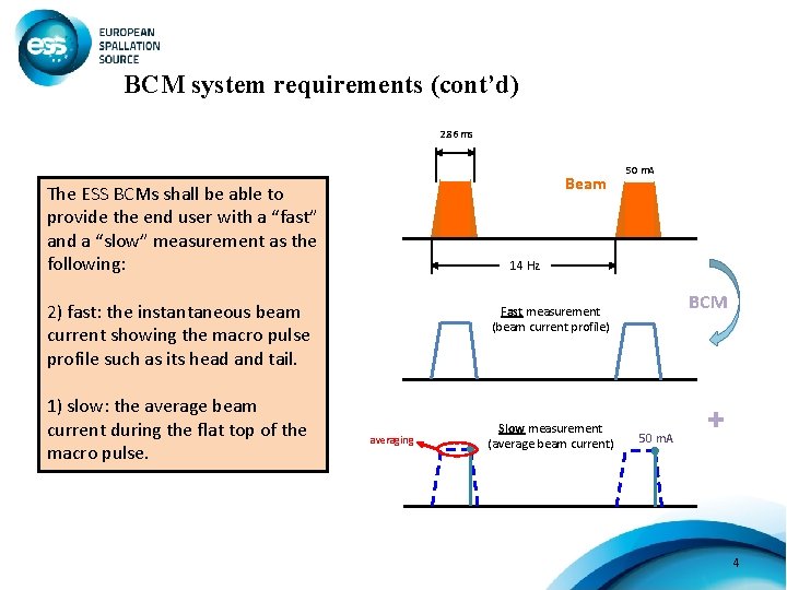
BCM system requirements (cont’d) 2. 86 ms Beam The ESS BCMs shall be able to provide the end user with a “fast” and a “slow” measurement as the following: 14 Hz 2) fast: the instantaneous beam current showing the macro pulse profile such as its head and tail. 1) slow: the average beam current during the flat top of the macro pulse. 50 m. A BCM Fast measurement (beam current profile) averaging Slow measurement (average beam current) 50 m. A + 4
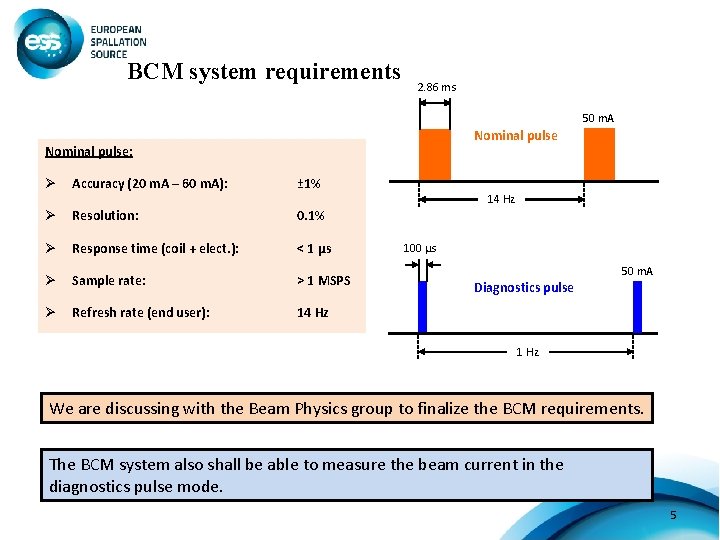
BCM system requirements 2. 86 ms 50 m. A Nominal pulse: Ø Accuracy (20 m. A – 60 m. A): ± 1% 14 Hz Ø Resolution: 0. 1% Ø Response time (coil + elect. ): < 1 μs Ø Sample rate: > 1 MSPS Ø Refresh rate (end user): 14 Hz 100 μs 50 m. A Diagnostics pulse 1 Hz We are discussing with the Beam Physics group to finalize the BCM requirements. The BCM system also shall be able to measure the beam current in the diagnostics pulse mode. 5
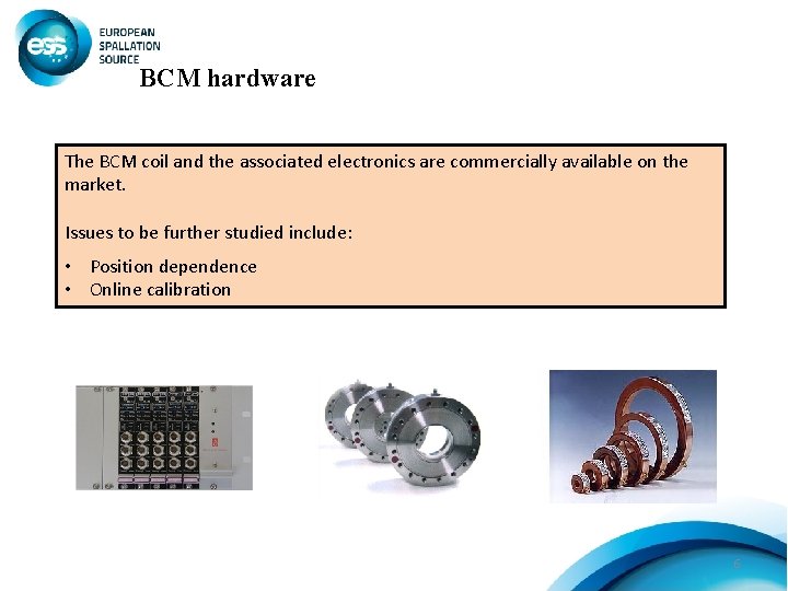
BCM hardware The BCM coil and the associated electronics are commercially available on the market. Issues to be further studied include: • Position dependence • Online calibration 6
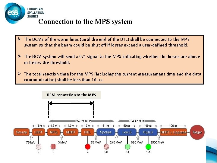
Connection to the MPS system Ø The BCMs of the warm linac (until the end of the DTL) shall be connected to the MPS system so that the beam could be shut off if losses exceed a user-defined threshold. Ø The BCM system will send a 0/1 signal to the MPS indicating whether the losses are above or below the threshold. Ø The total reaction time for the MPS (including the current measurement time and the data communication) shall be less than 10 s. BCM connection to the MPS 7
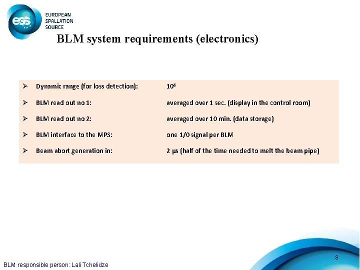
BLM system requirements (electronics) Ø Dynamic range (for loss detection): 106 Ø BLM read out no 1: averaged over 1 sec. (display in the control room) Ø BLM read out no 2: averaged over 10 min. (data storage) Ø BLM interface to the MPS: one 1/0 signal per BLM Ø Beam abort generation in: 2 μs (half of the time needed to melt the beam pipe) 8 BLM responsible person: Lali Tchelidze
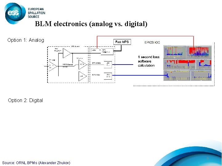
BLM electronics (analog vs. digital) Option 1: Analog Option 2: Digital 9 Source: ORNL BPMs (Alexander Zhukov)
Summary • We are still in the early stage of identifying our requirements for the BCM and BLM systems. • For both systems we have foreseen two types of data acquisition (i. e. fast and slow) to be used for machine protection or monitoring purposes. • We plan to connect both the BCM and the BLM system to the MPS so that we can shut the beam off if losses exceed a user defined threshold. • We are studying the possibility of doing part of the electronics in house or through external collaborations. As another possibility, the electronics can be bought from the market. 10
- Slides: 10