
BATTERYLESS IOT DEVICE SDDEC 19 21 ADVISOR DR
BATTERY-LESS IOT DEVICE SDDEC 19 -21 ADVISOR: DR. HENRY DUWE CLIENTS: DR. NATHAN NEIHART DR. DAJI QAIO HTTP: //SDDEC 19 -21. SD. ECE. IASTATE. EDU/

Antenna design and testing • Matthew Goetzman & Mohamed Gesalla Power System & Rectifier design and testing • Derek Nash & Adithya Basnayake MEMBER CONTRIBUTIONS Microcontroller functionality, communications, and testing • Mohammed Al-Mukhaini & Bradley Rhein Website design/maintenance • Mohammed Al-Mukhaini & Derek Nash Documentation • All members Outreach/ meeting coordination • Mohammed Al-Mukhaini

PROJECT PLAN
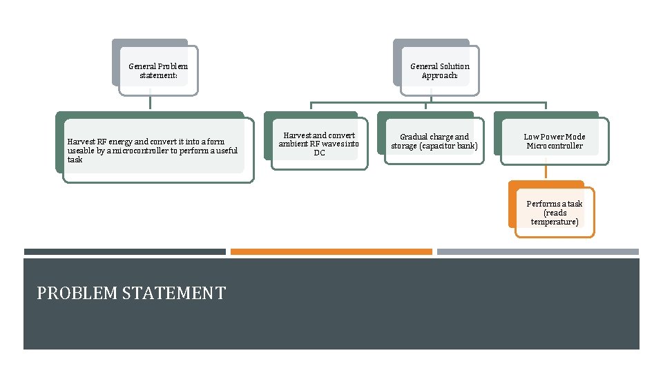
General Problem statement: Harvest RF energy and convert it into a form useable by a microcontroller to perform a useful task General Solution Approach: Harvest and convert ambient RF waves into DC Gradual charge and storage (capacitor bank) Low Power Mode Microcontroller Performs a task (reads temperature) PROBLEM STATEMENT
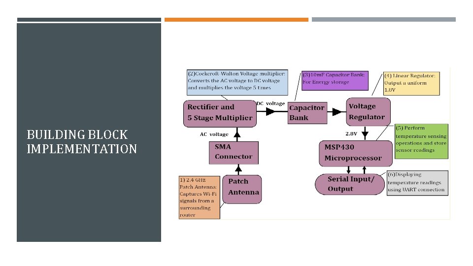
FUNCTIONAL REQUIREMENTS Energy Harvesting � Harvest RF signal from Wi. Fi router Power � Low voltage storage � Regulated Voltage supply to microcontroller Rectifier � Rectified & Multiplied voltage ≥ 2. 4 V Embedded Systems � MSP 430 microcontroller � Record temperature via internal ADC � Store and transmit data at a later time
NON-FUNCTIONAL REQUIREMENTS Portability ■ ■ Reasonable size for Prototype Compatible Efficiency ■ Reasonable operation and charging time Testability ■ Reliable for demonstration Reasonable cost ■ Under $100

MARKET / LITERATURE SURVEY ▪ ▪ ▪ Not many other manufacturers Powerspot kit o https: //www. powercastco. com/ o Focus on harvesting o Not communicating Huge Potential ▪ Network for battery-less devices ▪ Self-Sustaining ▪ Remotely located ▪ Dependable
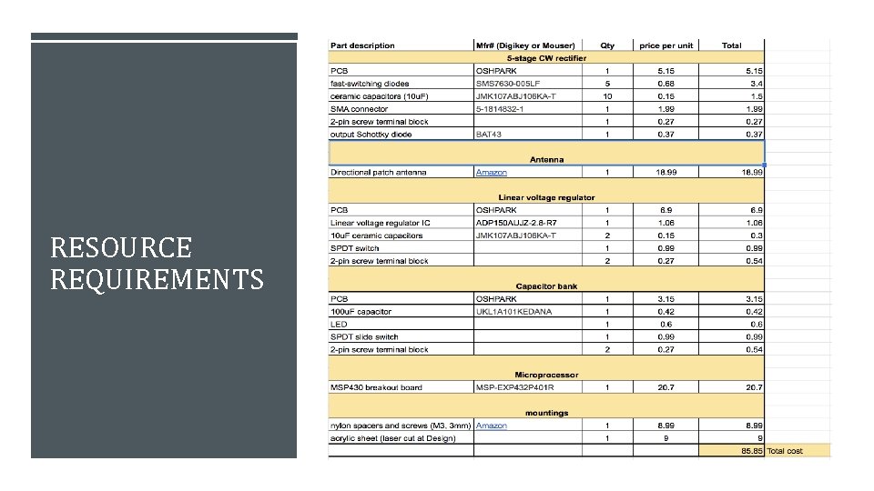
RESOURCE REQUIREMENTS
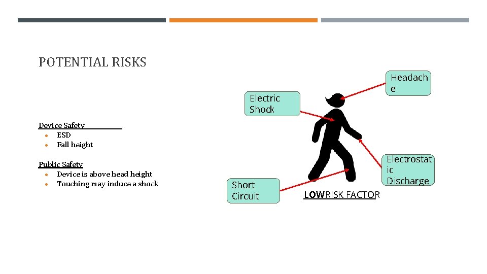
POTENTIAL RISKS Headach e Electric Shock Device Safety ● ESD ● Fall height Public Safety ● Device is above head height ● Touching may induce a shock Short Circuit Electrostat ic Discharge LOWRISK FACTOR

SYSTEM DESIGN
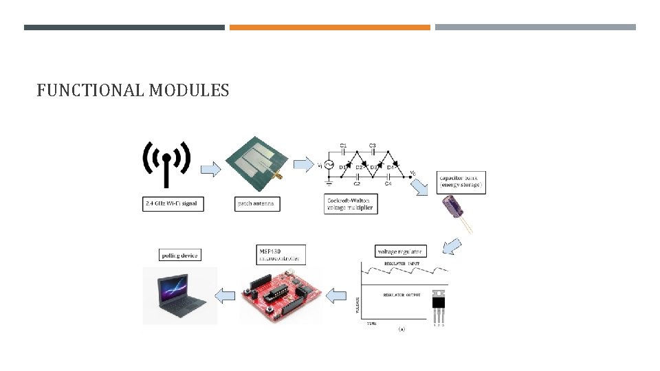
FUNCTIONAL MODULES
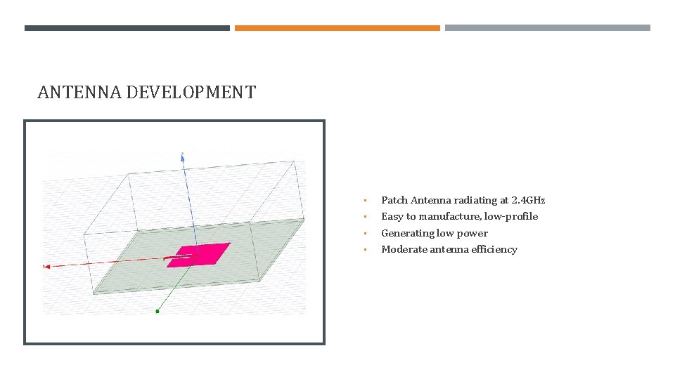
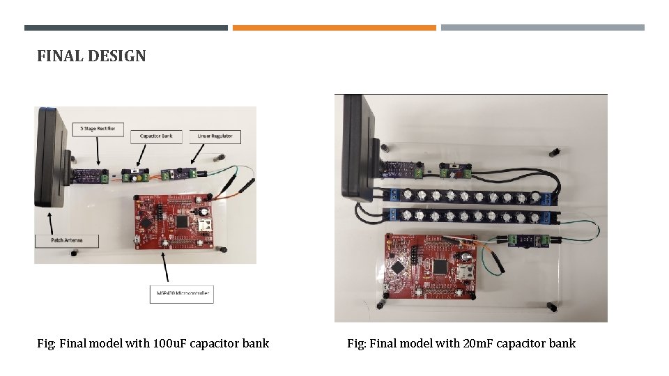
ANTENNA DEVELOPMENT • • Patch Antenna radiating at 2. 4 GHz Easy to manufacture, low-profile Generating low power Moderate antenna efficiency
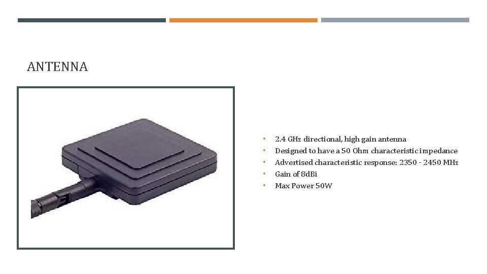
ANTENNA • • • 2. 4 GHz directional, high gain antenna Designed to have a 50 Ohm characteristic impedance Advertised characteristic response: 2350 - 2450 MHz Gain of 8 d. Bi Max Power 50 W
• ANTENNA: CHALLENGES & SOLUTIONS • Finding a good design for what we need: o High gain while still having a sizeable beamwidth o Size o Preferable a design that can be oriented in different directions Finding characteristic impedance that is already close to our rectifier input impedance.
IMPEDANCE MATCHING DEVELOPMENT • Parasitic models required to compensate for high frequency waves • Nonlinear diodes need to be impedance matched • S-Parameter measurement components not usable with our circuit • Target power efficiency may not be feasible no matter how well we match the circuit
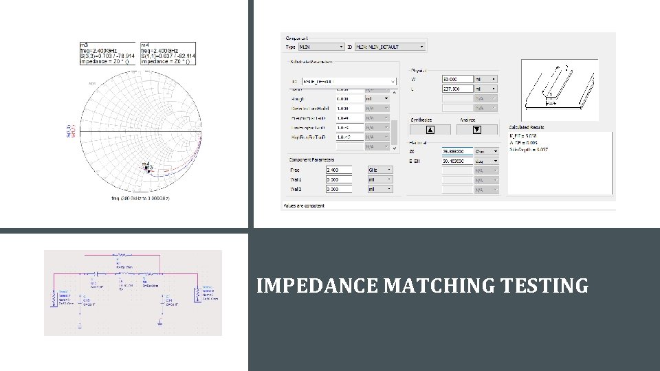
IMPEDANCE MATCHING TESTING
IMPEDANCE MATCHING CHALLENGES • Unfamiliar with the method of analysis required • Diodes are nonlinear components that respond differently to changes in power supplied • Mistakes made with taking measurements that costed time
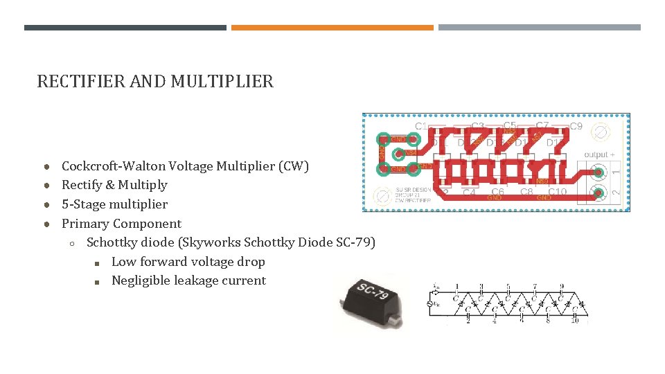
RECTIFIER AND MULTIPLIER ● Cockcroft-Walton Voltage Multiplier (CW) ● Rectify & Multiply ● 5 -Stage multiplier ● Primary Component ○ Schottky diode (Skyworks Schottky Diode SC-79) ■ Low forward voltage drop ■ Negligible leakage current
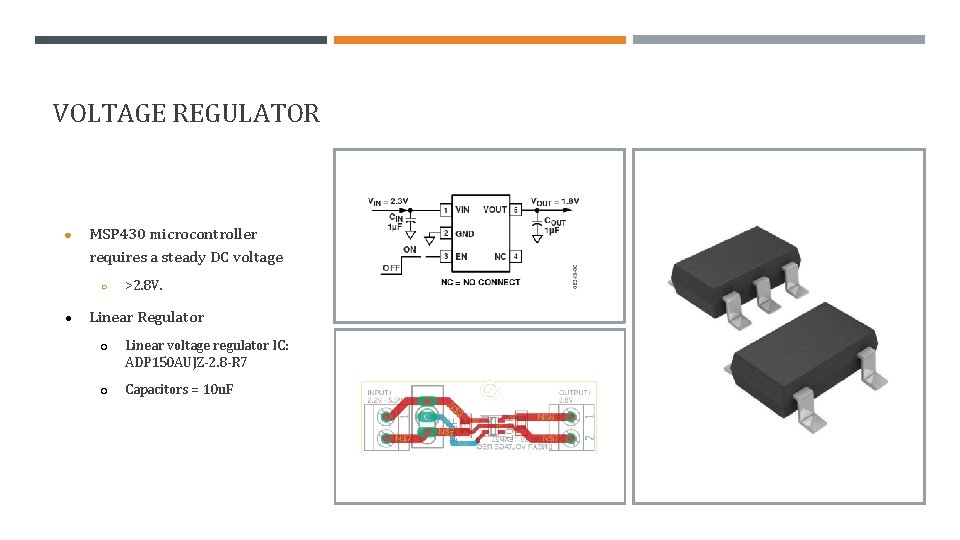
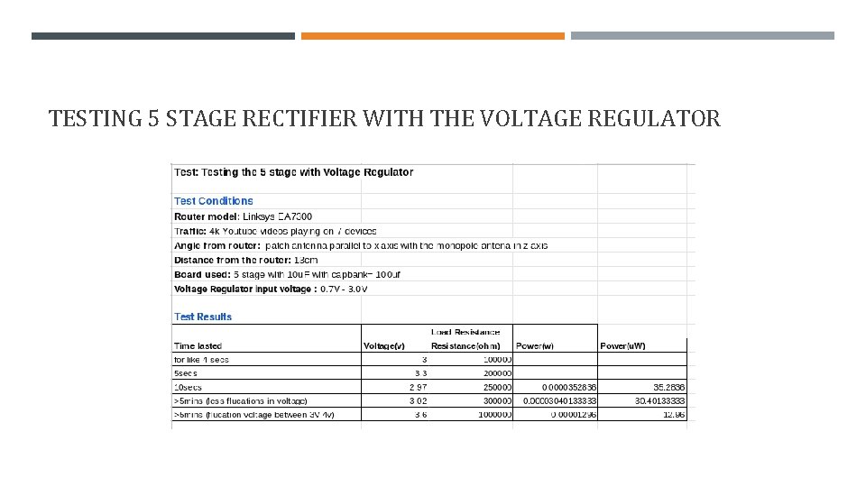
VOLTAGE REGULATOR ● MSP 430 microcontroller requires a steady DC voltage ○ ● >2. 8 V. Linear Regulator ○ Linear voltage regulator IC: ADP 150 AUJZ-2. 8 -R 7 ○ Capacitors = 10 u. F
POWER: CHALLENGES & SOLUTIONS • • Low-amplitude input voltage wave o Multi-stage Cockroft-Walton rectifier Wi. Fi is not a perfect sine wave o Schottky diode on CW output for stability Voltage on cap bank still somewhat variable o Used linear voltage regulator Leakage current o Use lower capacitance, higher quality materials
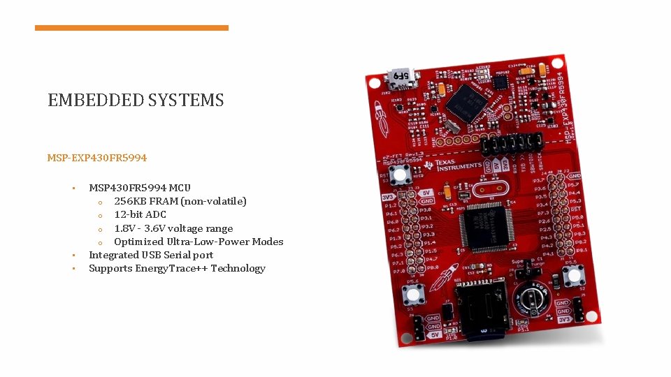
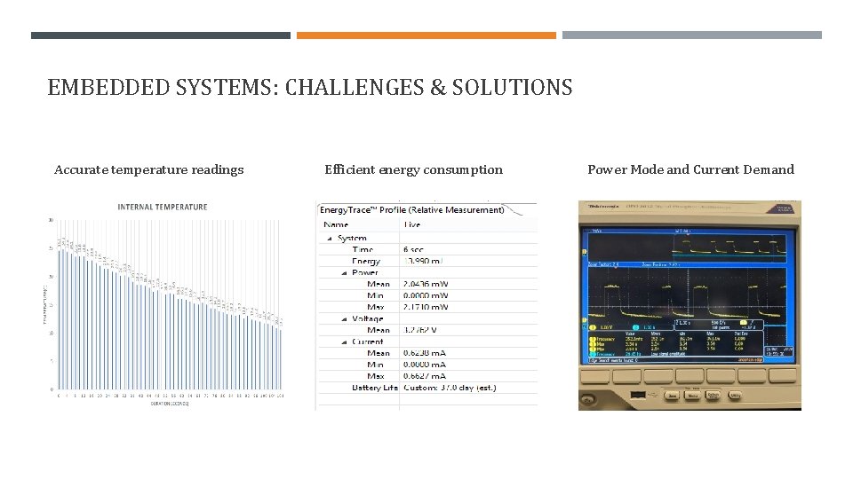
EMBEDDED SYSTEMS MSP-EXP 430 FR 5994 • • • MSP 430 FR 5994 MCU o 256 KB FRAM (non-volatile) o 12 -bit ADC o 1. 8 V - 3. 6 V voltage range o Optimized Ultra-Low-Power Modes Integrated USB Serial port Supports Energy. Trace++ Technology
EMBEDDED SYSTEMS: CHALLENGES & SOLUTIONS ● Serial Communication ● Outputting temperature readings ● Efficiency and Low Power Modes ● Persistent C variables
BUILDING BLOCK IMPLEMENTATION
BUILDING BLOCK IMPLEMENTATION
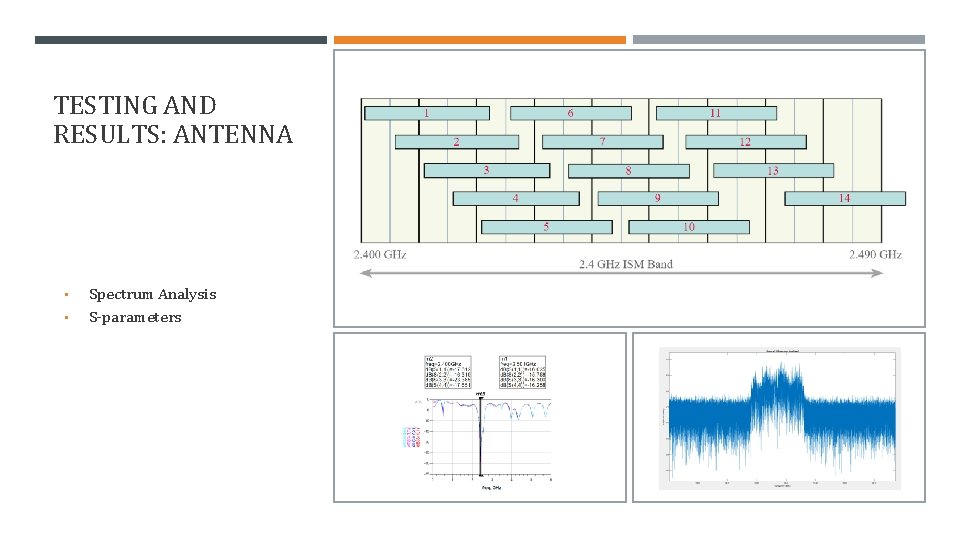
TESTING AND RESULTS: ANTENNA • • Spectrum Analysis S-parameters
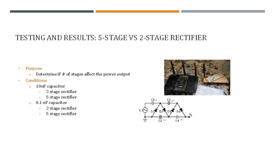
TESTING AND RESULTS: 5 -STAGE VS 2 -STAGE RECTIFIER • • Purpose o Determine if # of stages affect the power output Conditions o 10 u. F capacitor ▪ 2 stage rectifier ▪ 5 stage rectifier o 0. 1 u. F capacitor ▪ 2 stage rectifier ▪ 5 stage rectifier
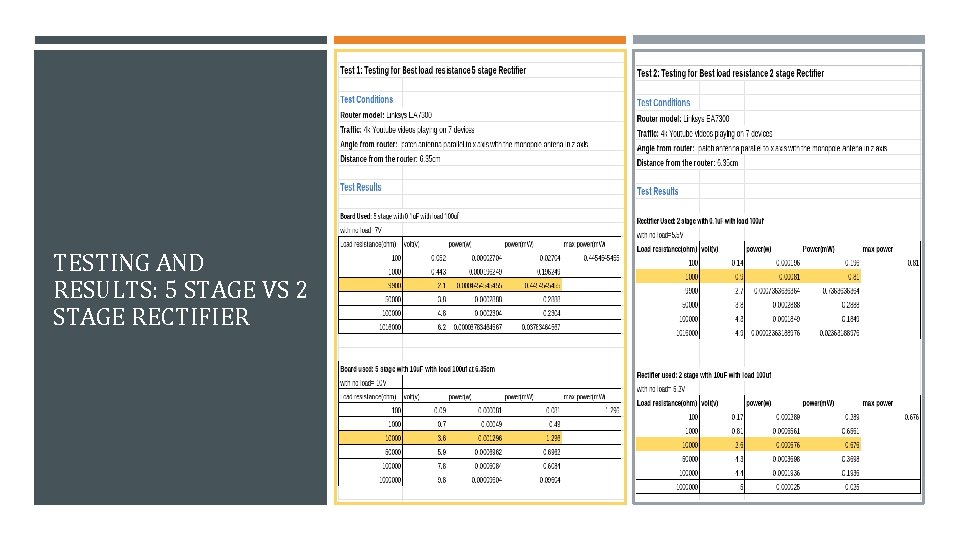
TESTING AND RESULTS: 5 STAGE VS 2 STAGE RECTIFIER
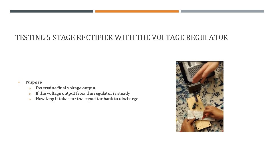
TESTING 5 STAGE RECTIFIER WITH THE VOLTAGE REGULATOR • Purpose o Determine final voltage output o If the voltage output from the regulator is steady o How long it takes for the capacitor bank to discharge
TESTING 5 STAGE RECTIFIER WITH THE VOLTAGE REGULATOR
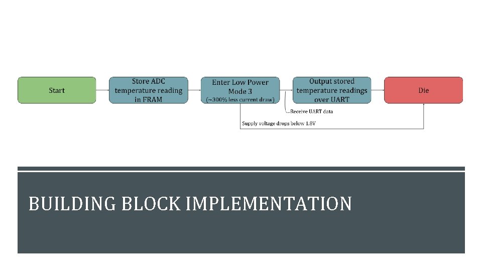
EMBEDDED SYSTEMS: CHALLENGES & SOLUTIONS Accurate temperature readings Efficient energy consumption Power Mode and Current Demand

DEMO
FINAL DESIGN Fig: Final model with 100 u. F capacitor bank Fig: Final model with 20 m. F capacitor bank
DEMO VIDEO � https: //youtu. be/gh. B 6 WJD 2 FEI
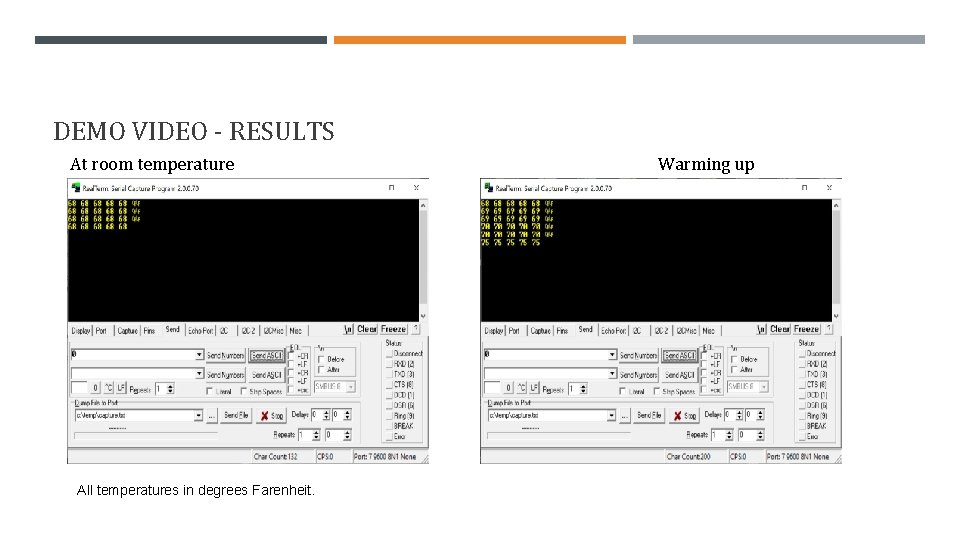
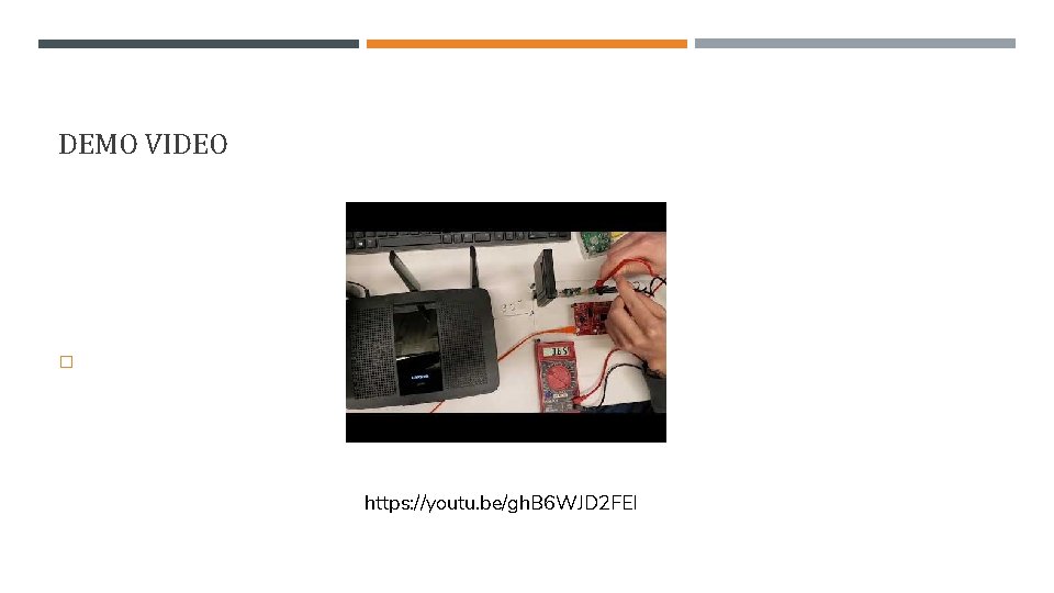
DEMO VIDEO - RESULTS At room temperature All temperatures in degrees Farenheit. Warming up

CONCLUSION
LESSONS LEARNED • Minimum voltage for operating MSP 430 is 3. 0 V • Check for commercial alternatives prior to committing to a design • Ground planes are easy improvements to PCBs • Inrush current can kill voltage regulators • Schottky diodes are linear in the forward region
CLIENT FEEDBACK • • • Get measurements/test as early as possible Larger capacitor bank is worth the added leakage current It’s OK to buy antenna instead of designing it Integrate a voltage regulator IC Met the portability requirement Understand delay times with ordering parts/supplies
IMPROVEMENTS • Adding impedance matching circuit for better efficiency • Change code design so that MCU can run under constant power • Adding a voltage supervisor in between the capacitor bank and the voltage regulator

QUESTIONS?
- Slides: 39