Basics of pacemaker part 1 Dr Suresh S

Basics of pacemaker part 1 Dr Suresh S SR, MCH Calicut
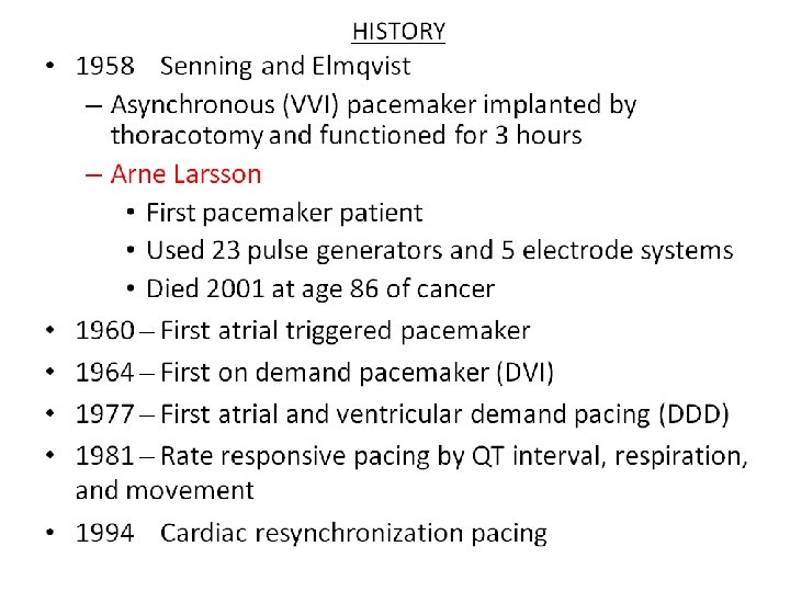

The Pacemaker System Cardiac Pacing is the artificial electrical stimulation of the heart in the absence of intrinsic heartbeats causing it to contract
: – Battery – Circuitry –")
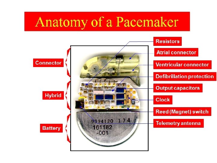
Implantable Pacemaker Circuit Leads • Implantable pulse generator (IPG): – Battery – Circuitry – Connector(s) IPG • Leads or wires – Cathode (negative electrode) – Anode (positive electrode) • Body tissue Anode Cathode

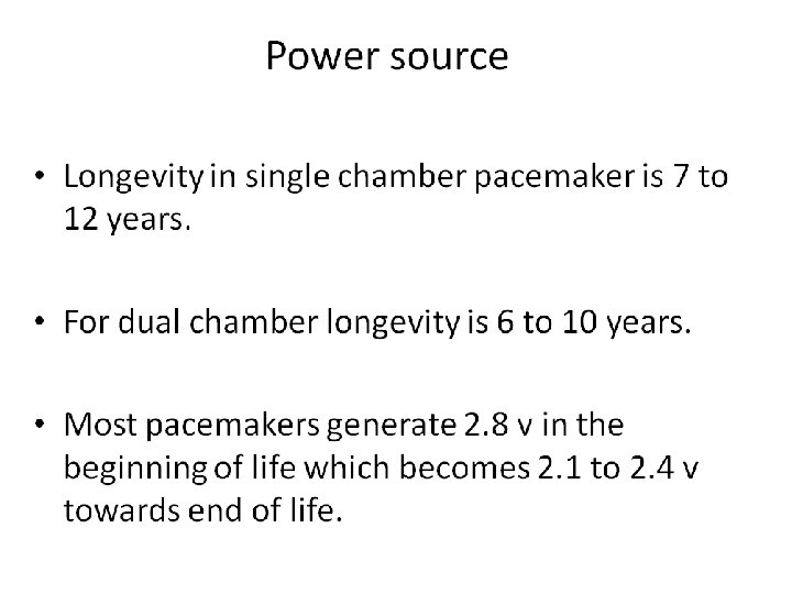
The Pulse Generator • Common battery compositions include: – Lithium-Iodine – Lithium silver vanadium oxide with carbon monoflouride – Starting battery voltage will vary depending on composition • Longevity – Dependent on impedance and output – Commonly ranges from 6 -12 years Circuitry Battery

Leads are Insulated Wires • Deliver electrical impulses from the pulse generator to the heart • Sense cardiac depolarization Lead
 – The tines become lodged in the trabeculae")
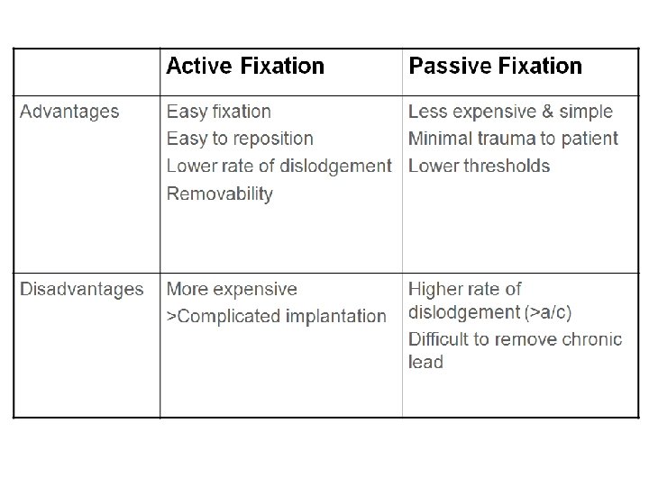
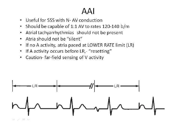
Transvenous Leads • Passive fixation (tined) – The tines become lodged in the trabeculae of the apex or the pectinate of the appendage which are fibrous meshworks of heart tissue • Active fixation (screw-in) – The helix, or screw, extends into the endocardial tissue • Allows for lead positioning anywhere in the heart’s chamber • The helix is extended using an included tool

Epicardial Leads • Leads applied directly to the surface of the heart – Utilized in pediatric patients and patients contraindicated for transvenous leads – Fixation mechanisms include: • Epicardial stab-in • Myocardial screw-in • Suture-on – Applied via sternotomy, thoroscopy, or limited thoracotomy

LEADS

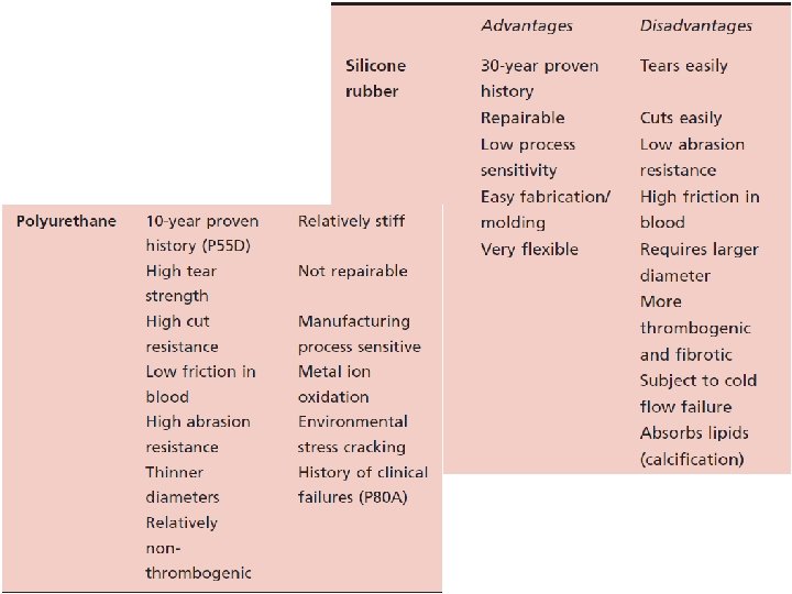
Lead Insulation May Be Silicone or Polyurethane Advantages of Silicone. Insulated Leads • Inert • Biocompatible • Biostable • Repairable with medical adhesive • Historically very reliable Advantages of Polyurethane. Insulated Leads • Biocompatible • High tear strength • Low friction coefficient • Smaller lead diameter
 Anode • Stimulates")
A Unipolar Pacing System • Flows through the tip electrode (cathode) Anode • Stimulates the heart • Returns through body fluid and tissue to the IPG (anode) - Cathode

A Bipolar Pacing System • Flows through the tip electrode located at the end of the lead wire • Stimulates the heart • Returns to the ring electrode above the lead tip Anode Cathode Tip electrode coil Indifferent electrode coil

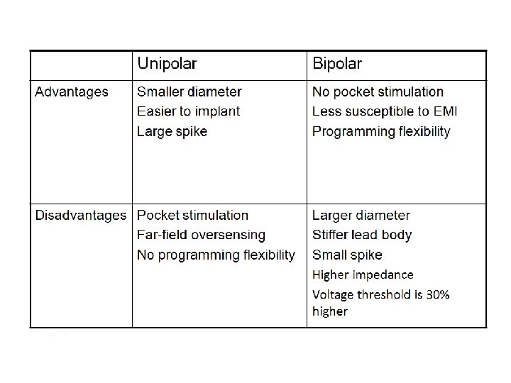
Lead Polarity • Unipolar leads – May have a smaller diameter lead body than bipolar leads – May exhibit larger pacing artifacts on the surface ECG – May cause pectoral muscle stimulation • Bipolar leads – Usually less susceptible to oversensing of non-cardiac signals (i. e. , myopotentials, EMI, From ring (anode) etc. ) Unipolar lead To tip (cathode) Bipolar coaxial lead

Characteristics of an electrical circuit: Including a pacemaker circuit • Voltage • Current • Impedance 24

Voltage • Voltage is the force, or “push, ” that causes electrons to move through a circuit • In a pacing system, voltage is: – Measured in volts (V) – Represented by the letter “V” – Provided by the pacemaker battery – Often referred to as amplitude or pulse amplitude

Current • The flow of electrons in a completed circuit • In a pacing system, current is: – Measured in milliamps (m. A) – Represented by the letter “I” – Determined by the amount of electrons that move through a circuit

Impedance • The opposition to current flow • In a pacing system, impedance is: – Measured in ohms (W) – Represented by the letter “R” – The measurement of the sum of all resistance to the flow of current

Voltage, Current, and Impedance are Interdependent • The interrelationship of the three components is analogous to the flow of water through a hose – Voltage represents the force with which. . . – Current (water) is delivered through. . . – A hose, where each component represents the total impedance: • The nozzle, representing the electrode • The tubing, representing the lead wire
 – In")
Voltage, Current, and Impedance • Voltage: The force moving the current (V) – In pacemakers it is a function of the battery chemistry • Current: The actual continuing volume of flow of electricity (I) – This flow of electrons causes the myocardial cells to depolarize (to “beat”) • Impedance: The sum of all resistance to current flow (R or W or sometimes Z) – Impedance is a function of the characteristics of the conductor (wire), the electrode (tip), and the myocardium 29

Voltage and Current Flow Electrical Analogies Water pressure in system is analogous to voltage – providing the force to move the current Spigot (voltage) turned up, lots of water flows (high current drain) Spigot (voltage) turned low, little flow (low current drain)

Resistance and Current Flow Electrical Analogies • Normal resistance – friction caused by the hose and nozzle • Low resistance – leaks in the hose reduce the resistance More water discharges, but is all of it going to the nozzle? • High resistance – a knot results in low total current flow

High Impedance Conditions A Fractured Conductor • A fractured wire can cause Impedance values to rise – Current flow from the battery may be too low to be effective • Impedance values may exceed 3, 000 W Lead wire fracture Increased resistance Other reason for high impedance: Lead not seated properly in pacemaker header (usually an acute problem).

Low Impedance Conditions An Insulation Break • Insulation breaks can cause impedance values to fall – Current drain is high and can lead to more rapid battery depletion – Current can drain through the insulation break into the body or other lead wire, not through myocardium • Impedance values may be less than 300 W

Ohm’s Law • Describes the relationship between voltage, current, and resistance • V = I X R • I = V / R V V • R = V / I I V = I X R R I = R V I = R

Ohm’s law tells us: 1. If the impedance remains constant, and the voltage decreases, the current decreases 2. If the voltage is constant, and the impedance decreases, the current increases

Status Check What happens to current if the voltage is reduced but the impedance is unchanged? • Start with: • Reduce the voltage to 2. 5 V – Voltage = 5 V – Impedance = 500 W – Current = 10 m. A – Impedance = 500 W – Current = ? • Solve for Current (I): – I = V/R – I = 5 V ÷ 500 W = 0. 010 Amps – Current is 10 m. A • Is the current increased/ decreased or unchanged? – I = V/R – V = 2. 5 V ÷ 500 W = 0. 005 Amps or 5 m. A • The current is reduced 36

Status Check What happens to current if the impedance is reduced but the voltage is unchanged? • Start with: • Reduce impedance to 250 W – Voltage = 5 V – Impedance = 500 W – Current = 10 m. A – Impedance = 250 W – Current = ? • Solve for Current (I): – I = V/R – I = 5 V ÷ 500 W = 0. 010 Amps – Current is 10 m. A • Is the current increased/ decreased or unchanged? – I = V/R – V = 2. 5 V ÷ 250 W = 0. 02 Amps or 20 m. A • The current is increased 37
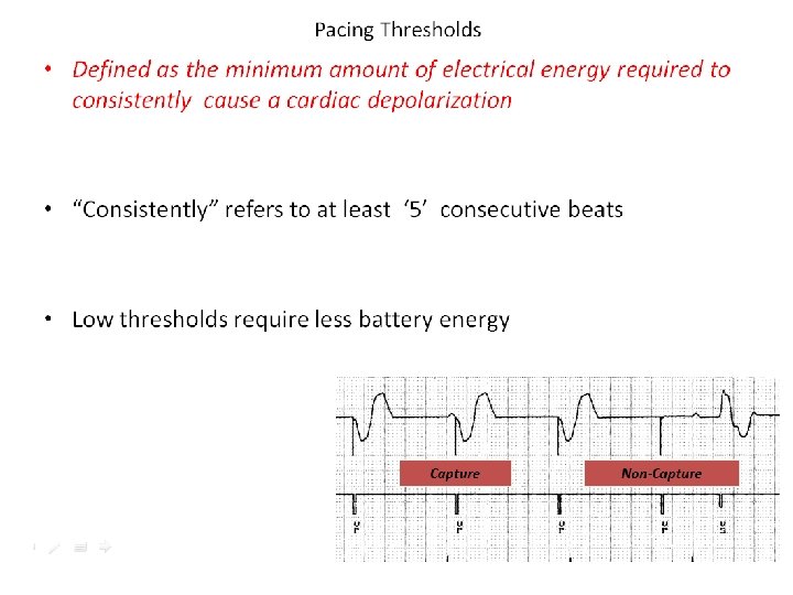

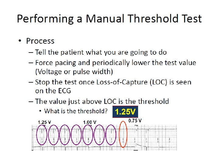
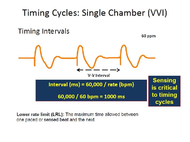
Capture Threshold The minimum electrical stimulus needed to consistently capture the heart outside of the heart’s own refractory period Ventricular pacemaker 60 ppm

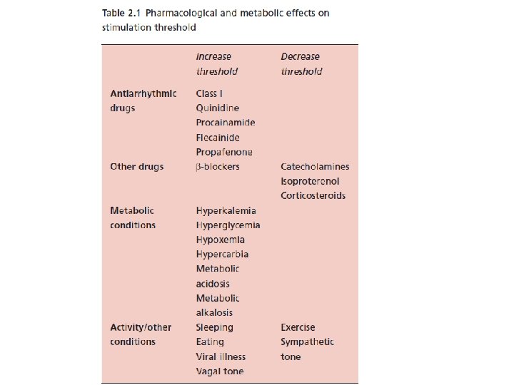
Effect of steroid on stimulation thresholds

Effect of Lead Design on Capture Lead maturation – Fibrotic “capsule” develops around the electrode following lead implantation – May gradually raise threshold – Usually no measurable effect on impedance

Steroid Eluting Leads Steroid eluting leads reduce the inflammatory process – Exhibit little to no acute stimulation threshold peaking – Leads maintain low chronic thresholds

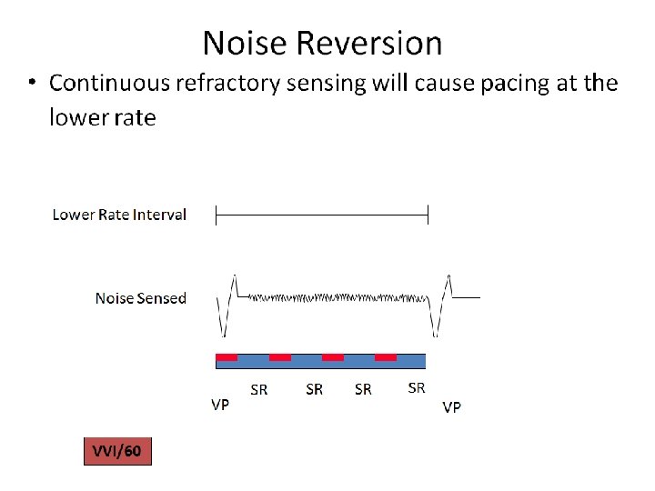
Electromagnetic Interference • Can interfere with function of pacemaker or ICD • Device misinterprets the EMI causing – Rate alteration – Sensing abnormalities – Asynchronous pacing – Noise reversion – Reprogramming

Electromagnetic Interference • Examples – Metal detectors – Cell phones – High voltage power lines – Some home appliances (microwave)

Electromagnetic Interference • Intensity of electromagnetic field decreases inversely with the square of the distance from the source • Newer pacemakers and ICDs are being built with increased internal shielding

Magnet mode I. II. Activates magnetic reed switch Model dependent behavior with magnet I. Asynchronous pacing – most common II. No apparent rate or rhythm change III. Brief asynchronous pacing and then return to programmed value IV. Continuous or transient loss of pacing III. Magnets will cause most DDDs to convert to DOO at about 85 with a BOL (beginning of life) battery, and to VOO at a rate of about 65 at ERI (effective replacement interval) is reached to conserve power.
 ASYNCH Boston")
Pacemaker Company Magnet Explanation Mode Designation AUTO Biotronik (except INOS and DROMOS) ASYNCH Boston Scientific/Guidant Medical/CPI Medtronic ASYNCH If battery okay, 10 asynchronous events at 90 beats/min, then returns to original programmed mode, without rate responsiveness. Pacing is at the lowest available rate (LRL, sleep rate, or hysteresis rate). If battery at ERI, 10 asynchronous events at 80 beats/min in the VOO mode, then either VDD (dual-chamber) or VVI (single-chamber) pacing at 11% lower than the lowest available rate. For any dual-chamber mode (DDD, DDI, or VDD), the AV delay shortens to 100 msec while the magnet is in place Asynchronous pacing at 90 beats/min if battery okay. At ERI, 80 beats/min (single-step change) in the VOO mode regardless of original programming. For any dual-chamber mode (DDD, DDI, or VDD), the AV delay shortens to 100 msec while the magnet is in place If battery okay, pacing in original programmed mode, without rate responsiveness. Pacing is at the lowest available rate (LRL, sleep rate, or hysteresis rate). If battery at ERI, either VDD (dual-chamber) or VVI (single-chamber) pacing at 11% lower than the lowest available rate. For any dual-chamber mode (DDD, DDI, or VDD), the AV delay shortens to 100 msec while the magnet is in place Asynchronous pacing at 100 beats/min if okay, 85 beats/min at ERI (single-step change). The Insignia model has an intermediate step at 90 beats/min at IFI. For Triumph and Prelude models, see Medtronic pacemakers, below OFF EGM mode No change, magnet is ignored. OFF is the magnet mode after a “power on reset, ” which can occur secondary to EMI No change in pacing. Magnet application initiates data collection Asynchronous pacing at 85 beats/min if okay, SSI at 65 beats/min regardless of original programming if ERI detected (single-step change). Most Medtronic pacemakers emit one or more ventricular pulses during the first 3 -7 asynchronous events (which might be at a rate of 100 beats/min) at a reduced pulse width or voltage to demonstrate the adequacy of ventricular pacing output. Also, Medtronic pacemakers default to SSI pacing at 65 beats/min, without rate responsiveness, on detection of ERI, regardless of whether a magnet is present Battery Test OFF Asynchronous pacing at 98. 6 beats/min gradually decreasing to <86. 3 beats/min at ERI No magnet response “SJM” x- Event snapshots No change in pacing. Magnet application causes pacemaker to collect data. Identity and Entity models lack this feature ray logo Event snapshots For a magnet placed 2 seconds, pacing mode and rate are unchanged and the device stores an EGM. If the magnet is placed ≥ 5 + seconds, the Battery Test mode (see above) is activated. Identity and Entity models lack this feature St. Jude Battery Test Medical (not Asynchronous pacing, with rate depending on the specific model. In general, a pacing rate of less than 90 beats/min should Battery Test including prompt further evaluation Telectronics) OFF No magnet response Pacesett er x-ray VARIO results in a series of 32 asynchronous pacing events. The rate of the first 16 paces reflects battery voltage, which gradually VARIO mode logo (ψ) declines from 100 to 85 beats/min at ERI. The next 15 paces are used to document the ventricular pacing capture safety margin. (present in some The rate will be 119 beats/min with gradually declining pacing voltage. The 16 th pace of this group is at no output. The next pace models) restarts the 32 -event sequence. The 32 -event sequence repeats as long as the magnet remains in place

Activity Sensors • Activity sensors employ a piezoelectric crystal that detects mechanical signals produced by movement • The crystal translates the mechanical signals into electrical signals that in turn increase the rate of the pacemaker Piezoelectric crystal

Rate-adaptive/rate-modulated pacing I. normal heart rate response to increased physiological demand is linearly related to oxygen demand/consumption II. greater proportion of rate-adaptive sensors belong to a secondary class of sensors that detect physiological changes as a consequence of exercise such as: I. such as QT interval shortening II. increase in respiratory or minute-ventilation rate III. increased mean atrial rate IV. rise in central venous temperature V. decrease in venous blood p. H VI. increase in right ventricular stroke volume VII. increase in ventricular inotropy (e. g. peak endocardial acceleration and ventricular impedence variation).
")
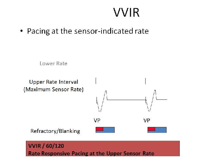
Rate Responsive Pacemakers Rate-Responsive Pacing Fixed-Rate Pacing Normal Heart Rate Running Heart Rate (bpm) 150 100 Walking Wake-up Sleeping Sitting Resting 50 0 Daily Activities

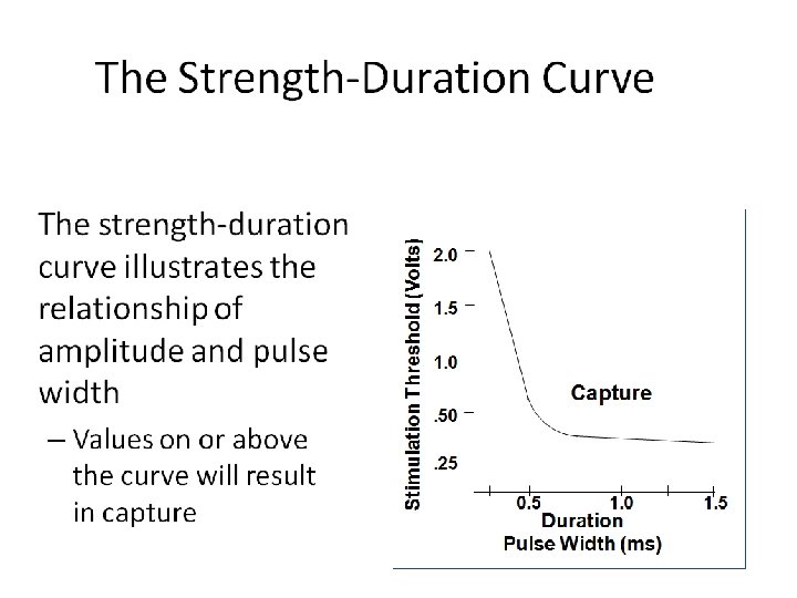
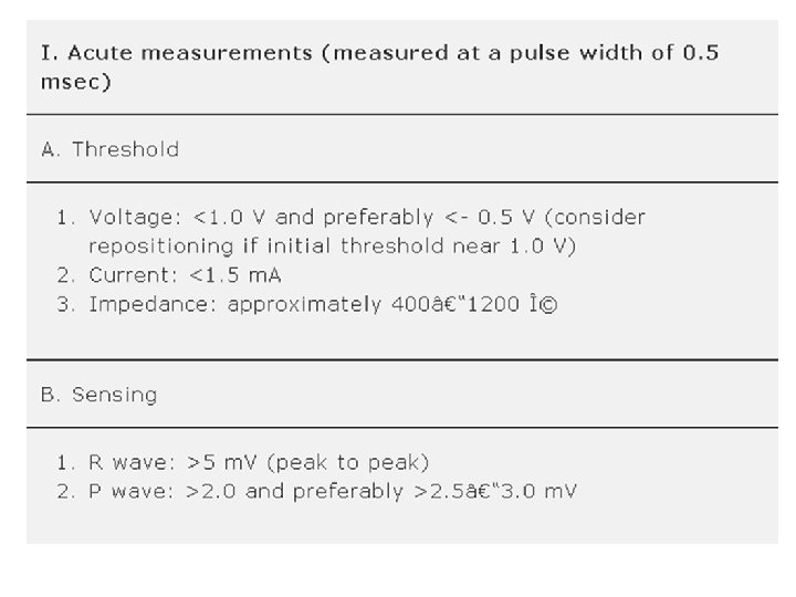
Stimulation Threshold • Pacing Voltage Threshold – The minimum pacing voltage – at any given pulse width – required to consistently stimulate the heart – outside the myocardial refractory period causing it to contract

Capture – Loss of Capture VVI / 60 Non-Capture
 the curve")
The Voltage-Strength Duration Curve • At short pulse widths (<0. 25 ms) the curve rises sharply • At long pulse widths (>1. 0 ms) the curve is flat 2. 0 Stimulation Threshold (Volts) • Stimulus Voltage & Pulse Width have an exponential relationship 1. 5 1. 0 Capture . 50. 25 1. 0 Duration Pulse Width (ms) 1. 5
 (say 2. 5 V)")
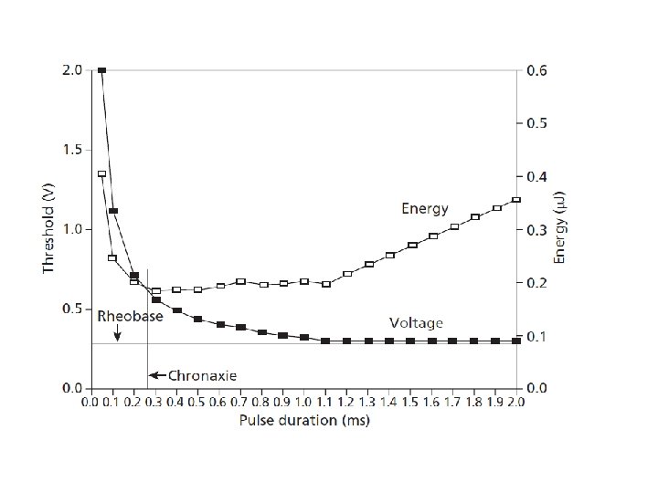
The Pacing Pulse V = Pulse Amplitude in Volts (V) (say 2. 5 V) t Output Voltage Pacing Pulse t = Pulse Duration or Width in milliseconds (ms) (say 0. 5 ms) R = Impedance of Pacing Circuit (ohms) (say 500 ohms) V I = V/R = Current through pacing circuit (m. A) = 2. 5 V/ 500 ohms = 0. 005 A = 5 m. A t Pulse Duration (Width) E = Energy delivered by Pulse to the Pacing Circuit and Cardiac Tissue = V. I. t = I 2 Rt = V 2 t/R = 2. 5 V. 5 m. A. 0. 5 ms = 6. 25 micro Joules If V = 5 V Energy = 25 micro Joules

Why measure stimulation threshold? • To enable programming stimulus voltage amplitude and pulse width such that – Consistent capture & Patient Safety is ensured – Battery drain minimized, Pacemaker longevity maximized – Good thresholds • Ventricle - <1 V @ 0. 5 ms • Atrium - <1. 5 V @ 0. 5 ms
 s Safety Margin 4 3 2")
Evolution of Pacing Threshold 6 Voltage Threshold (V) s Safety Margin 4 3 2 Chronic Phase 1 Acute Phase 0 4 8 Observation Time (weeks) 12 16

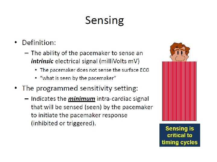
Sensing of intrinsic heartbeats • Sensing is the ability of the pacemaker to “see” when an intrinsic depolarization is occurring – Pacemakers record the Intracardiac Electrogram (EGM) by constantly recording the potential difference between the cathode and anode Depolarization Wave Processed by Device
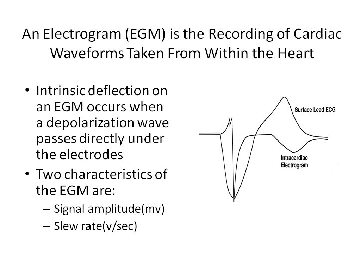

Intrinsic R wave Amplitude • Intrinsic R wave amplitude 5 m. V • Intrinsic P wave amplitude 2 m. V Amplitude Intrinsic R wave in EGM The Intrinsic R wave amplitude is usually much greater than the T wave amplitude
 5. 0")
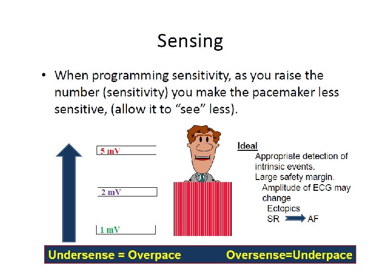
Sensitivity Setting 2. 5 1. 25 Time 5. 0 Amplitude (m. V) 5. 0 2. 5 1. 25 Time Sensitivity settings less than 2. 5 mv – High sensitivity – can lead to oversensing Sensitivity settings greater than 2. 5 m. V – Low sensitivity – can lead to undersensing

Undersensing. . . • Pacemaker does not “see” the intrinsic beat, and therefore does not respond appropriately Intrinsic beat not sensed Scheduled pace delivered VVI / 60

Oversensing Marker channel shows intrinsic activity. . . though no activity is present • An electrical signal other than the intended P or R wave is detected • Pacing is inhibited

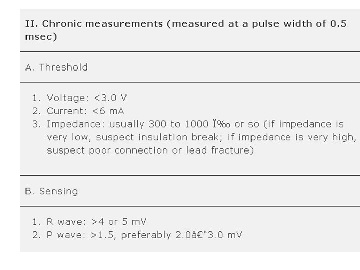
Values to remember § § § Pacing Thresholds § Atrium - <1. 5 V; Ventricle <1 V @ 0. 5 ms PW Outputs § 2 X threshold Voltage § Doubling Voltage output = 4 X Energy drain from battery P / R wave amplitudes § P Wave > 2 m. V § R Wave > 5 m. V Sensitivity § R / P wave > 2 X Sensitivity setting § Oversensing – Increase sensitivity ( Reduce value) § Undersensing – Reduce sensitivity ( Increase value) Lead impedance § 300 – 1200 ohms – Normal § > 3000 Ohms - lead fracture / Loose set screw / inadequate lead pin insertion § < 300 Ohms – Insulation break § If impedance is out of range – try unipolar configuration
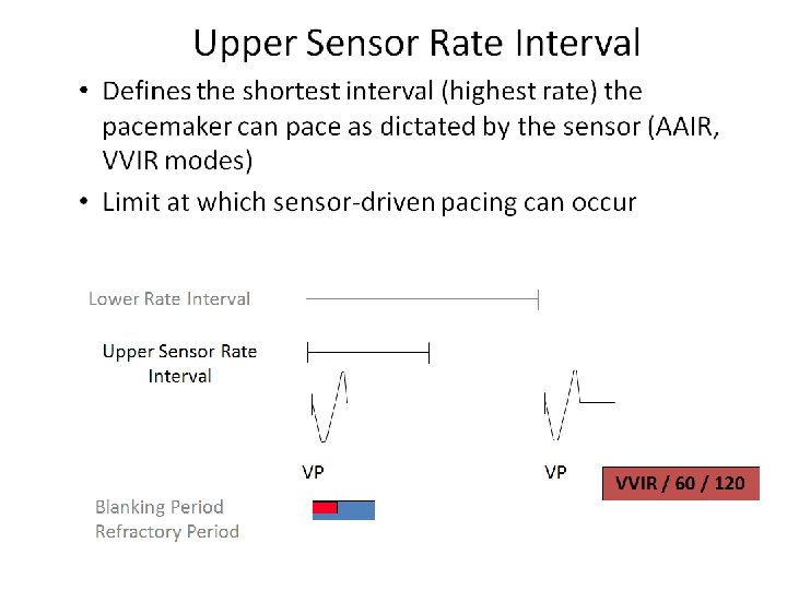
 Paced Chamber(s) Sensed Response to Sensing")
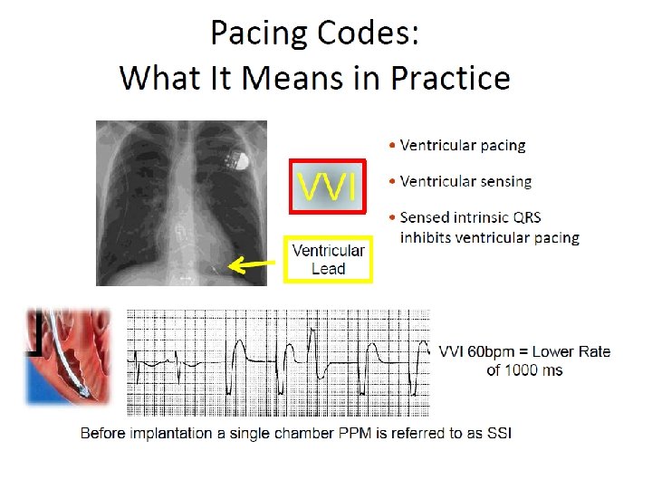
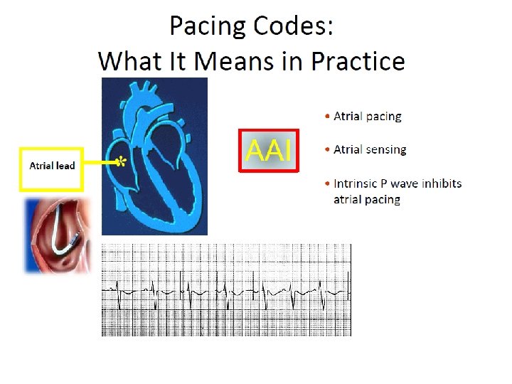
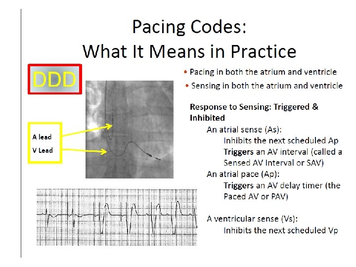
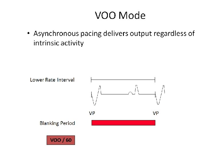
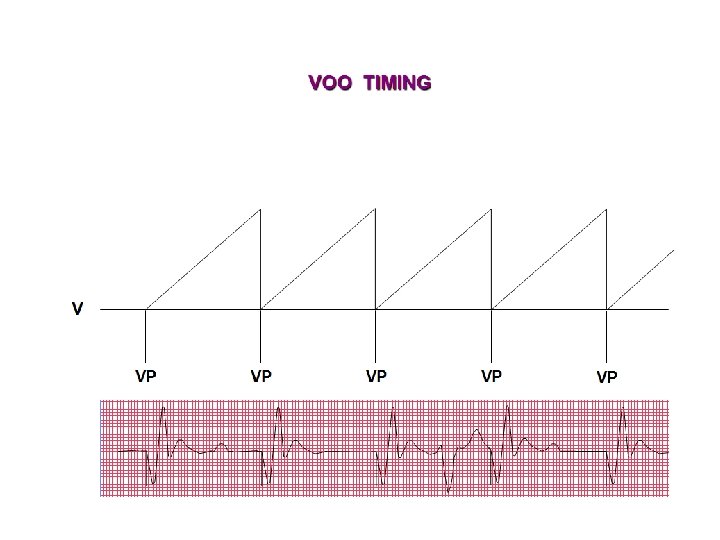
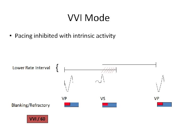
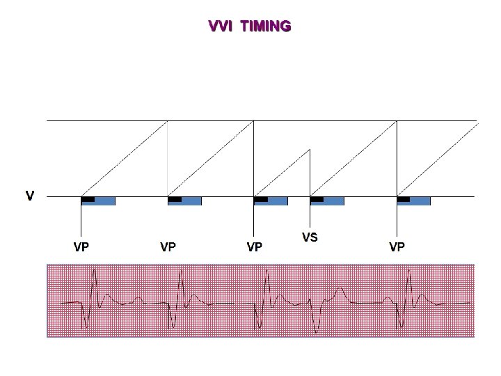
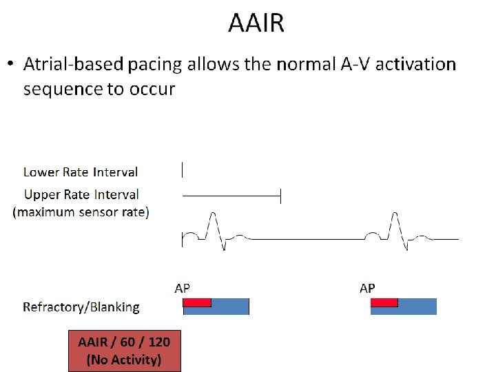
NBG Code – The Usual Pacing Modes Chamber(s) Paced Chamber(s) Sensed Response to Sensing Rate Modulation Multisite Pacing O = None A = Atrium V = Ventricle D = Dual (A +V) + V) S = Single (A or V) O = None A = Atrium V = Ventricle D = Dual (A + V) S = Single (A or V) O = None T = Triggered I = Inhibited D = Dual (T + I) O = None R = Rate modulation O = None A = Atrium V = Ventricle D = Dual (A + V) Examples of pacing modes which are typically programmed: DDD VVI DDIR DDDR VVIR AAIR

- Slides: 98