
Basics of Microwave Measurements Steven Anlage http www

Basics of Microwave Measurements Steven Anlage http: //www. cnam. umd. edu/anlage/Anlage. Microwave. Measurements. htm 1
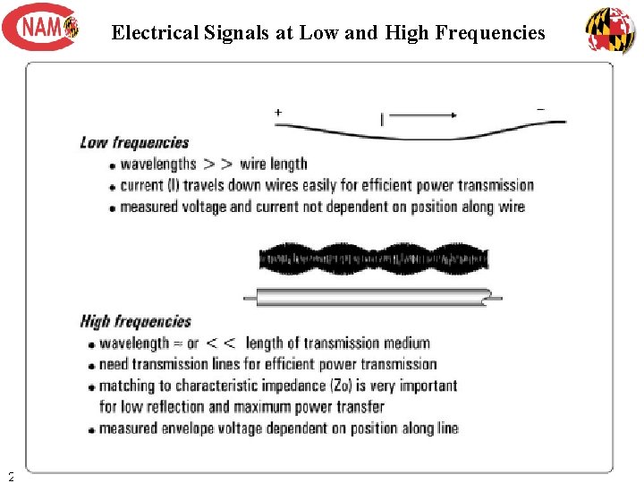
Electrical Signals at Low and High Frequencies 2

Transmission Lines Transmission lines carry microwave signals from one point to another They are important because the wavelength is much smaller than the length of typical T-lines used in the lab You have to look at them as distributed circuits, rather than lumped circuits V The wave equations 3
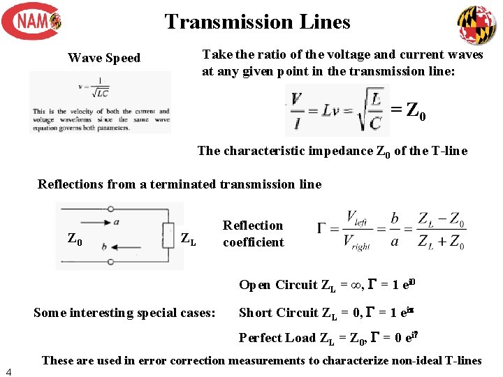
Transmission Lines Take the ratio of the voltage and current waves at any given point in the transmission line: Wave Speed = Z 0 The characteristic impedance Z 0 of the T-line Reflections from a terminated transmission line Z 0 ZL Reflection coefficient Open Circuit ZL = ∞, G = 1 ei 0 Some interesting special cases: Short Circuit ZL = 0, G = 1 eip Perfect Load ZL = Z 0, G = 0 ei? 4 These are used in error correction measurements to characterize non-ideal T-lines
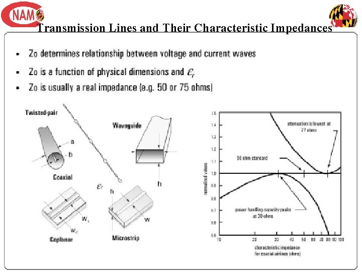
Transmission Lines and Their Characteristic Impedances 5

Transmission Lines, continued The power absorbed in a termination is: Model of a realistic transmission line including loss Shunt Conductance Traveling Wave solutions 6 with
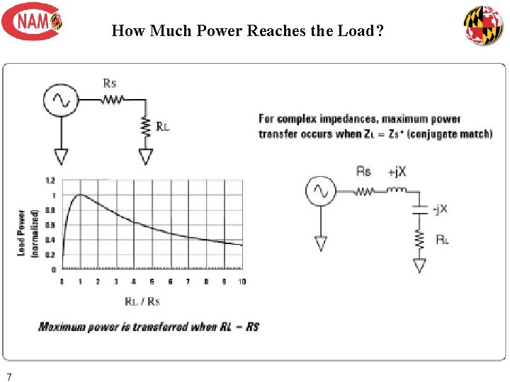
How Much Power Reaches the Load? 7
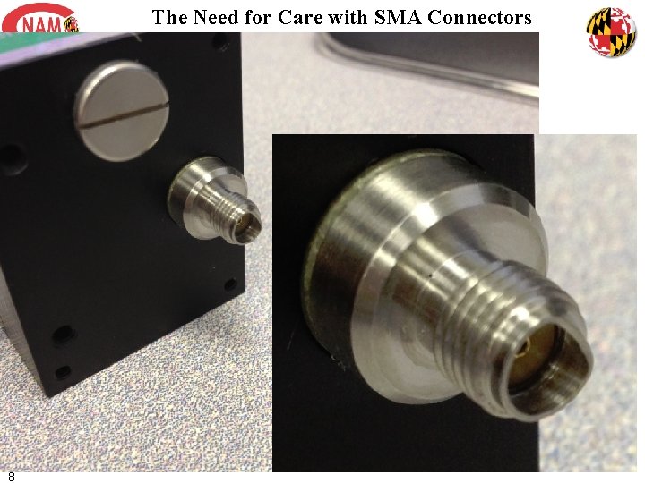
The Need for Care with SMA Connectors 8
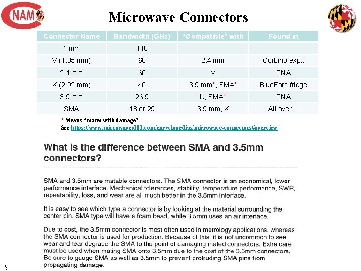
Microwave Connectors Connector Name Bandwidth (GHz) “Compatible” with Found in 1 mm 110 V (1. 85 mm) 60 2. 4 mm Corbino expt. 2. 4 mm 60 V PNA K (2. 92 mm) 40 3. 5 mm*, SMA* Blue. Fors fridge 3. 5 mm 26. 5 K, SMA* PNA SMA 18 or 25 3. 5 mm, K All over… * Means “mates with damage” See https: //www. microwaves 101. com/encyclopedias/microwave-connectors#overview 9
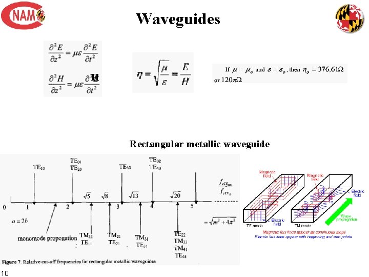
Waveguides H Rectangular metallic waveguide 10
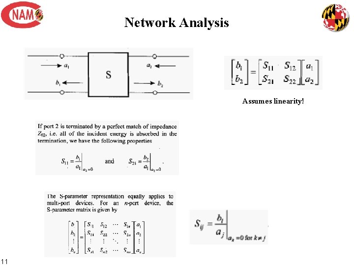
Network Analysis Assumes linearity! 11
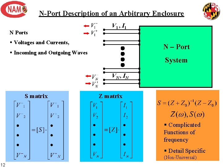
N-Port Description of an Arbitrary Enclosure N Ports V 1 , I 1 § Voltages and Currents, N – Port § Incoming and Outgoing Waves System V N , IN S matrix Z matrix § Complicated Functions of frequency § Detail Specific (Non-Universal) 12
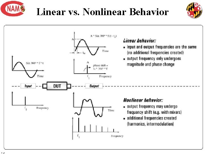
Linear vs. Nonlinear Behavior 13
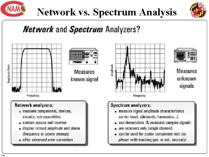
Network vs. Spectrum Analysis 14
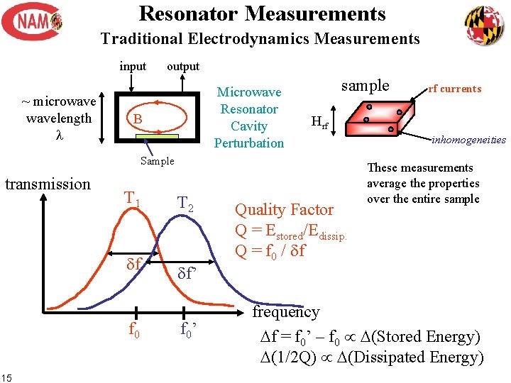
Resonator Measurements Traditional Electrodynamics Measurements input ~ microwavelength l output Microwave Resonator Cavity Perturbation B sample Hrf Sample transmission T 1 df f 0 15 T 2 df’ f 0’ rf currents Quality Factor Q = Estored/Edissip. Q = f 0 / df inhomogeneities These measurements average the properties over the entire sample frequency Df = f 0’ – f 0 D(Stored Energy) D(1/2 Q) D(Dissipated Energy)
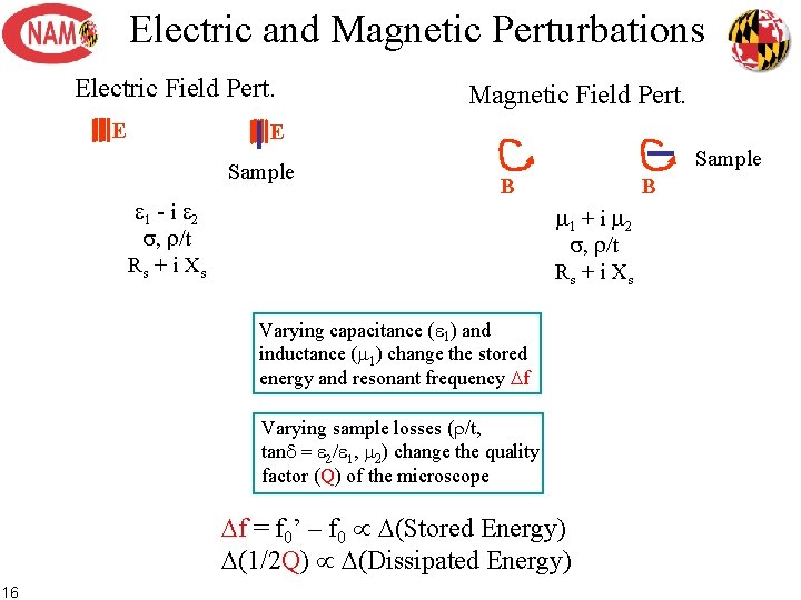
Electric and Magnetic Perturbations Electric Field Pert. E Magnetic Field Pert. E Sample e 1 - i e 2 s, r/t Rs + i X s Sample B B m 1 + i m 2 s, r/t Rs + i X s Varying capacitance (e 1) and inductance (m 1) change the stored energy and resonant frequency Df Varying sample losses (r/t, tand = e 2/e 1, m 2) change the quality factor (Q) of the microscope Df = f 0’ – f 0 D(Stored Energy) D(1/2 Q) D(Dissipated Energy) 16
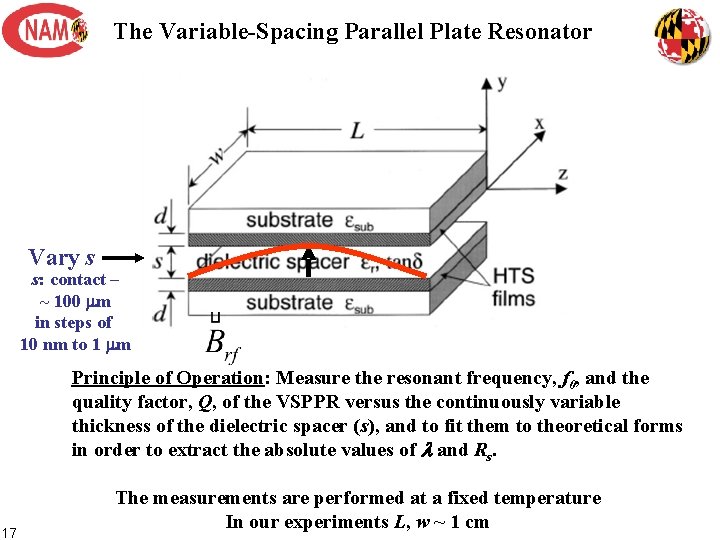
The Variable-Spacing Parallel Plate Resonator Vary s s: contact – ~ 100 mm in steps of 10 nm to 1 mm Principle of Operation: Measure the resonant frequency, f 0, and the quality factor, Q, of the VSPPR versus the continuously variable thickness of the dielectric spacer (s), and to fit them to theoretical forms in order to extract the absolute values of l and Rs. 17 The measurements are performed at a fixed temperature In our experiments L, w ~ 1 cm
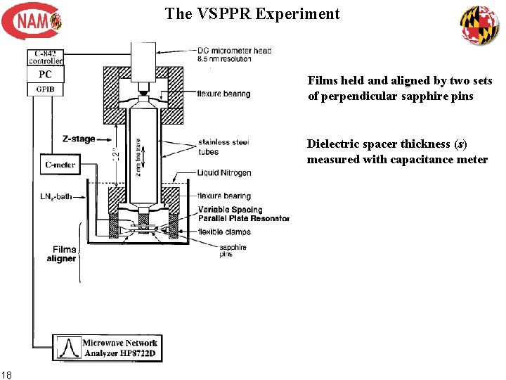
The VSPPR Experiment Films held and aligned by two sets of perpendicular sapphire pins Dielectric spacer thickness (s) measured with capacitance meter 18
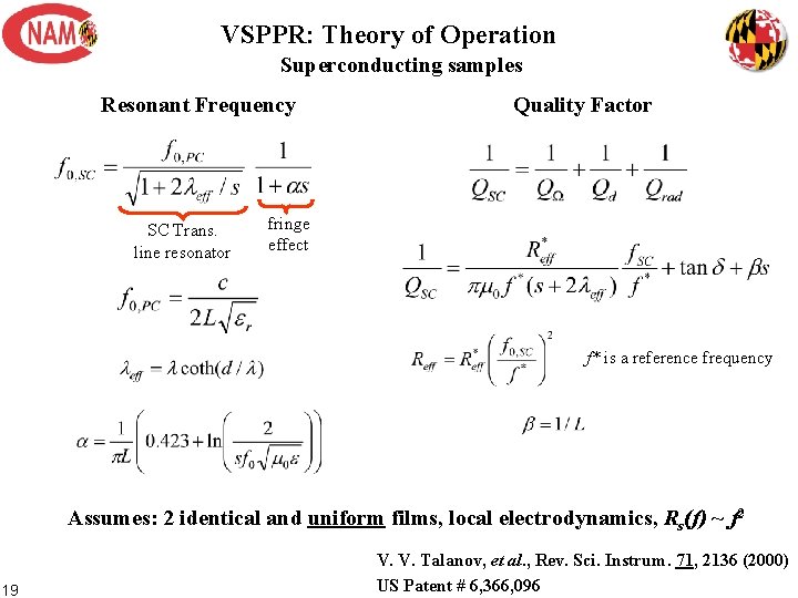
VSPPR: Theory of Operation Superconducting samples Resonant Frequency SC Trans. line resonator Quality Factor fringe effect f* is a reference frequency Assumes: 2 identical and uniform films, local electrodynamics, Rs(f) ~ f 2 19 V. V. Talanov, et al. , Rev. Sci. Instrum. 71, 2136 (2000) US Patent # 6, 366, 096
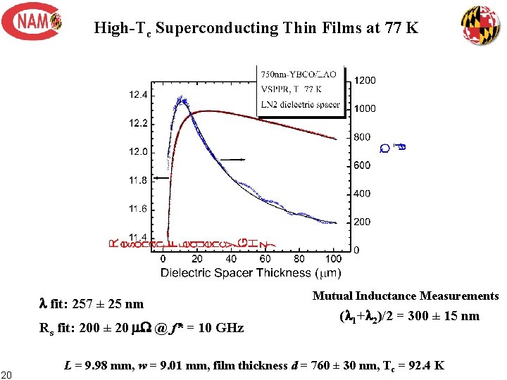
High-Tc Superconducting Thin Films at 77 K l fit: 257 ± 25 nm Rs fit: 200 ± 20 m. W @ f* = 10 GHz 20 Mutual Inductance Measurements (l 1+l 2)/2 = 300 ± 15 nm L = 9. 98 mm, w = 9. 01 mm, film thickness d = 760 ± 30 nm, Tc = 92. 4 K
- Slides: 20