Basic tricks of Atomic Absorption Spectrophotometry AAS technique

Basic `tricks’ of Atomic Absorption Spectrophotometry AAS technique üutilizes 1 element SOURCE üAtomizes sample The overall advantages of AAS: üEliminates N 2 problem present in UV-VIS approach, e. g. can study elements in mixture as if independent of each other üMUCH more sensitive to low concentrations (to 0. 1 ppm) üWith standard addition, eliminates matrix effects
 schematic (Skoog pg 219 Fig 9 -13 a)")
Single Beam Atomic Absorption Spectrophotometer (AAS) schematic (Skoog pg 219 Fig 9 -13 a) : the least expensive version 5)Computer readout 4) Transducer (PMT) 3) Wavelength selector (Ebert Monochromator, 1 mirror) 1) source=HCL Hollow Cathode Lamp (1 element lamp) 2) `cell’=flame=sample=slotted burner + nebulize

DOUBLE BEAM AAS DESIGN (ASC’s PE Aanalyst 200 is double beam: fig 9. 13 b) ~*echellette grating with 2 focusing mirrors 4) Wavelength selector (Czerny. Turner Monochromator*, 2 mirrors) 1) source=HCL 2)chopper 5) Transducer (PMT) 3) cell’=flame=sample 6)Computer readout
 Advantages 1)Chopper")
DOUBLE BEAM AAS DESIGN ASC’s PE Aanalyst 200 is double beam (continued) Advantages 1)Chopper allows ratioing of flame vs no flame condition (instrument background removed) 2) lock-in amp filters all but chopper frequency signals out (lower noise, more sensitivity) Disadvantage …a bit more expensive
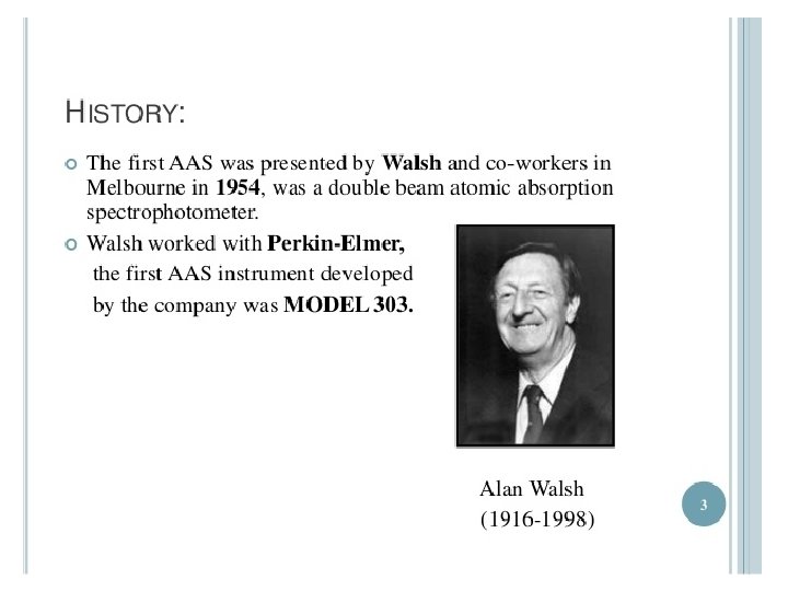

Original PE model 303
 is computerized version of original 303 by Walsh which")
PE Model 3030 (circa 1980) is computerized version of original 303 by Walsh which Alfred had until ~2008 Optical bench and burner design are essentially identical to 303
")
Perkin Elmer AAnalyst 300 circa 2010 (ASC has AAS 200 with single source port) Gas handling plumbing Slotted burner HCL sources nebulizer Waste tube Sampling capillary

Top View of PE Aanalyst 200 Czerny-Turner Monochromator pathway and PMT under here (`reference pathway). It is rare to open the chassis up to see it
")
AAS source =HCL= Hollow Cathode Lamp (made of single element)
 Anode (+) Step 1 Ar `sputtering’ off 300 volts")
How HCL works: (Skoog 217) Anode (+) Step 1 Ar `sputtering’ off 300 volts e. Ar Ar+* hot M by Argon ion M(g)*+Ar(g) Cathode -) Ar+* + e- (to anode) +* accelerated by 300 V towards (-) Ar Step 2 cathode made of M(s) and collides to neutralize Ar and eject hot M(g)* Ar+* + M(s) + e- Ar + M(g)* Step 3 hot M(g)* releases energy as light specific to atomic M M(g)* M(s) + h (specific to atomic M)
 (pumps rf waves into lamp with metal…vaporizes and causes")
Alternative `EDL’ (electrodeless discharge lamp) (pumps rf waves into lamp with metal…vaporizes and causes emission: figure 9 -12 p 218) Higher light output (100 X) => can measure very low concentrations Low life time (100 h ? ) vs years w/HCL
 burner with nebulizer Nebulizer")
AAS `sample cell’ design that achieves atoms: laminar flow (slotted’) burner with nebulizer Nebulizer Slotted burner Perkin-Elmer Laminar flow burner design: Fig. 9 -5 p 213
 Want to sample free")
Getting atoms of sample (Skoog Fig 9 -2 p 211) Want to sample free atoms Acetylene –air: 2100 -2400 o. C Acetylene-O 2 : 2600 -2800 o. C Acetylene-N 2 O: 3050 -3150 o. C

Flame profiles vary with element and burner position With PE Aanalyst 200 some of this is adjusted automatically via lamp tuning

Flame temperature varies sharply within flame Fig. 9 -3 p. 212 Sweet spot
 you adjusted to")
In the `good’ old days (with PE 303 and PE 3030) you adjusted to maximum signal by manually changing: • flame height • nebulizer opening • Lamp focus Now (with PE Aanalyst 200): • Lamp focus and lamp height are adjusted to maximize signal automatically. • You can manually adjust flame height and nebulizer, but the auto-tune is usually good enough (and lamp height adjust usually maximizes to correct flame height) • But…make sure slotted burner sits straight !

Flame AAS in operation Light from HCL lamp passes down the length of the flame In AAS, the flame is the cell

To discard jug One draw back of slotted laminar flow design~99% of sample is discarded by nebulizer

One way to avoid using up lots of sample: Graphite Furnace (=Electrothermal method= HGA Fig. 9 -6 p. 214) Uses a single microliter drop inside of Lvov platform Light goes through graphite tube (Lvov platform where sample is dried, ashed and `flashed’ Lvov platform
 platforms • Electrical contact is made across graphite")
PE 3030 HGA furnac Lvov (graphite) platforms • Electrical contact is made across graphite tube w/high pressure clamps • Argon flows around tube to keep it from burning up • Massive current surge applied to reach 2400 C quickly
")
HGA in operation (flash part of dry-ash-flash)
 in 2 u.")
Typical electrothermal analysis: fig. 9 -7 p. 215 Lead (Pb 2+) in 2 u. L volume of orange juice
Sensitivity compared Element flame 2)Accuracy compared furnace Cu 2 ppb 1")
Flame vs furnace 1)Sensitivity compared Element flame 2)Accuracy compared furnace Cu 2 ppb 1 0. 05 Ni 3 0. 5 As 200 0. 5 Hg 500 5* 1 0. 001 ppm = 1 ppb units From table 9 -3 Skoog p 249 Furnace AAS more sensitive Flame 0. 1 -2 % Furnace 10 -20% Flame is more accurate
 can do only one (1) element at a time")
Limitations of AAS Method 1) can do only one (1) element at a time 2) Chemical interferences (see Skoog pp 222 -224)
 • Natural (Heisenburg Uncertainty) Line width~0.")
AAS Line width factors (see pp. 200 -202) • Natural (Heisenburg Uncertainty) Line width~0. 00001 nm • Doppler broadening: ~0. 001 nm • Pressure (collisional) broadening: 0. 010. 001 nm

Chemical interferences Why burner head design is the `Achilles heel’ of AAS The main issue: Many metal carbonates, sulfates and phosphates are hard to dissolve and nebulize into small, easily atomized mists. Often, they reform solids (rocks) in burner slot Ca. CO 3 mp 1330 C Ca 3(PO 4)3 mp 1670 C

1 -2 cm 1300 -2400 o. C
 Add soluble release agents like La(NO 3)2 or")
FIXES to burner head particulates a) Add soluble release agents like La(NO 3)2 or Sr(NO 3)2 which tie up carbonates, sulfates, phosphates and `release’ analysis metals Example: Sr(NO 3)2 (aq) + Ca. CO 3 (s) Sr(CO 3)(s) + Ca(NO 3)2 (aq) b) Add protective (chelating) agents e. g. EDTA to protect analysis metals in a volatile, soluble form Example: EDTA(aq)4 - + Ca 2+ Ca(EDTA)2 -(aq)
 Flame reactions lead to metal hydroxides in flame=> chemical")
Limitations of AAS Method (continued) Flame reactions lead to metal hydroxides in flame=> chemical broadening(and signal loss) No sure fix except to go to higher temperatures… but AAS can’t get to requisite values
…the best")
` Fixes’ for AAS Chemical Broadening • Change atomization method (Table 8. 1)…the best choice • Change sample introduction technique (Table 8. 2)

BEST ALTERNATIVE TO AAS…Inductively Coupled Plasma Atomic Emission Spectroscopy = ICP AES (or just ICP) (Skoog pp 231 -241) § allows simultaneous element analysis §Removes chemical interferences §Often better sensitivity Main “trick” for ICP Get atoms hot enough that they start to produce significant fluorescence and observe these atomic emissions directly and simultaneously. FYI: Flame AAS also produces emissions and we can do AES (Atomic Emission Flame Spectrophotometry )with our PE Aanalyst 200 instrument
 Wavelength selector (stepper + concave grating* 3) Transducer array (many PMT detectors arranged")
2) Wavelength selector (stepper + concave grating* 3) Transducer array (many PMT detectors arranged at predetermined slots) *echelle grating is less flattened than concave echelette type and allows 2 D dispersion (p 261 fig 10 -7) Source focusing optics 1) Cell and source 4) readouts Classic (old style) Rowland circle design (Fig. 10 -8 p. 239)

1 Source and Cell: the plasma torch ~ outer corona of Sun’s T Figure 10 -3 Figure 10 -1 Main source of high temperature is collisions in flame called ohmic heating)
 in the flesh")
1: Source (and cell) in the flesh
 Venting for Ar and")
Perkin-Elmer Optima 200 ICP (latest/ greatest ~ 200 -250 k$) Venting for Ar and torched samples 0) Sample sucked into nebulizer through capillaries 1) torch 4) Data collection 2) Echelle monochromator, Nebulizer in here 3) 2 D PMT array and relevant optics all in here Power supply (1 k. W) for torch down here Receives rejected solution from nebulizer
 Wavelength dispersion: the Echelle Monochromator 2 D dispersion See")
Traditional flat echellete grating 2) Wavelength dispersion: the Echelle Monochromator 2 D dispersion See page 165 -172 (section 7 C-2 of Skoog) 2 Wavelength selector For ICP: flat `Echelle’ grating Echelle grating Always used in conjunction with a dispersing prism 2 D
 Wavelength dispersion (continued) A graphical picture of how 2 D dispersion works")
2) Wavelength dispersion (continued) A graphical picture of how 2 D dispersion works

3 Transducers in ICP ‘Old school’ Arrangement (Rowland circle with many PMT on circle to measure individual …big footprint) `New School’ Charge-coupled 2 D detection (CCD) (see previous slide also)

A bit more on CCD (Charge Coupled Devices (see also, page 198 -199 of text) From Echelle + dispersing prism Families of related colors across CCD essentially keeps track of charge collected for defined period at every pixel. Charge ~ light intensity Boyles and Smith AT & T Bell Labs 1969

CCD requires several chips to time and keep track of the many pixel data points
 for Three Atomic Spectral Methods Taken from Page 226")
Minimum detection limits (in ppb) for Three Atomic Spectral Methods Taken from Page 226 Table 9. 3 of text element AAS HGA ICP Al 30 0. 1 0. 2 Cu 2 0. 05 0. 04 Fe 6 0. 25 0. 09 Ni 3 0. 5 0. 2 Cr 4 0. 03 0. 08

Ready for some drill and practice about ICP ? ? ?
- Slides: 43