Basic Step index Fiber Structure Fiber Optics Communication

Basic Step index Fiber Structure Fiber Optics Communication Technology-Mynbaev & Scheiner

Ray Trajectories in Step Index fiber Meridional Rays Skew Rays

Fig. 2 -13: Light propagation

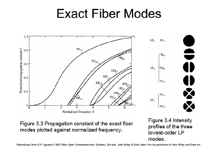
Rays and Their E-field Distribution

Fig. 2 -14: Low-order-mode fields

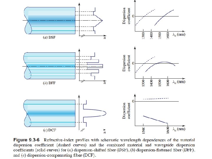
Fig. 2 -10: Comparison of fiber structures

Absorption & scattering losses in fibers Optical Fiber communications, 3 rd ed. , G. Keiser, Mc. Graw. Hill, 2000

Optical fiber attenuation vs. wavelength Optical Fiber communications, 3 rd ed. , G. Keiser, Mc. Graw. Hill, 2000

Bending Loss
 • Macrobending Loss: The curvature of the bend is much larger")
Bending Loss (Macrobending) • Macrobending Loss: The curvature of the bend is much larger than fiber diameter. Lightwave suffers sever loss due to radiation of the evanescent field in the cladding region. As the radius of the curvature decreases, the loss increases exponentially until it reaches at a certain critical radius. For any radius a bit smaller than this point, the losses suddenly becomes extremely large. Higher order modes radiate away faster than lower order modes. Optical Fiber communications, 3 rd ed. , G. Keiser, Mc. Graw. Hill, 2000

Microbending Loss • Microbending Loss: microscopic bends of the fiber axis that can arise when the fibers are incorporated into cables. The power is dissipated through the microbended fiber, because of the repetitive coupling of energy between guided modes & the leaky or radiation modes in the fiber. Optical Fiber communications, 3 rd ed. , G. Keiser, Mc. Graw. Hill, 2000

Minimizing microbending losses: A compressible jacket extruded over a fiber reduces microbending resulting from external forces.

Minimum safe bend radius —shown full size

Bends are shown full size — and may have caused damage to the fiber

Experimental comparison of Loss as a function of mechanical misalignment

OTDR

There are two main sources of returned light on an optical fiber link: Backscatter Reflection OTDR pulse Fiber End of Fiber Connection Fusion splice
 as")
Backscatter Rayleigh scattering occurs continuously along optical fiber (at very small power levels) as the result of microscopic fluctuations of the fiber’s index of refraction. Scattered photons that are recaptured by the fiber and travel back toward the OTDR constitute backscatter. OTDR pulse Fiber End of Fiber Connection Fusion splice
 reflections are caused by major changes in group index of refraction")
Reflection Fresnel (“fra-nel”) reflections are caused by major changes in group index of refraction that occur at “reflective events” on fiber links such as connections, mechanical splices, and the end of the fiber. Fusion splices generally cause such little change in group index of refraction that they are considered “non-reflective” events. OTDR pulse Fiber Connection Fiber Fusion splice End of Fiber

Pulse Laser Fiber Under Test Coupler Clock “E” P Processor, memory, display etc. “O” DSP ADC (Digital Signal (Analog to Processor) Digital Converter) Sample and Hold APD (Detector) and Amplifier OTDR Block Diagram

Samples Time Outbound pulse timedistance line Pulse hits fiber end Distance OTDR Link under test “Time – distance” view of OTDR operation

By knowing the speed of light in fiber, the OTDR converts sample times to distances: Since OTDR sample times represent round-trip times: Di = [Sample Time/2] x [Speed of Light in Fiber] Di = [T i / 2] x [c / N] c = speed of light in a vacuum (about 2. 99 x 108 N = group index of refraction for the fiber under Where: m/s) test For example, for T = 10 ns and assuming N = 1. 5: D = = = (10 x 10 – 9)/2 x (3 x 10 8)/1. 5 (5 x 10 – 9) x (2 x 10 8) 1 meter An OTDR could therefore estimate distance in meters simply by dividing sample times in nanoseconds by 10. In fact, OTDRs use

Samples Time Outbound pulse timedistance line Pulse hits fiber end Distance OTDR Link under test . . . or graphically:

And by averaging samples from 100 s or 1000 s of pulses. . . Relative Power (d. B) “Very small” pulse Distance Horiz. Backbone OTDR Total Link Length OTDR Range
 distance “Very small” pulse")
Creates a trace of power vs. Relative Power (d. B) distance “Very small” pulse Distance Horiz. OTDR Backbone OTDR Range Total Link Length

Reading an OTDR Trace Launch Cable Horizontal Segment Backbone Segment OTDR Patch Cord Receive Cable Link being tested Splice Link Length ( 130 m) A 0 -1 Relative Power (d. B) B (1) Connection (Loss 0. 4 d. B) (2) Connections (Loss 0. 8 d. B) (1) Connection (Loss 0. 4 d. B) Link Loss ( 2. 1 d. B) -2 OTDR screen Splice (Loss 0. 1 d. B) -3 Launch Cable Horiz. Seg. Backbone Segment Rcv. Cable Trace -4 0 50 100 150 Distance (m) 200 250
- Slides: 32