BASIC PRINCIPLES OF WEATHER RADAR RADAR Introduction to

BASIC PRINCIPLES OF WEATHER RADAR

RADAR • • Introduction to Radar Basic Operating Principles Reflectivity Products Doppler Principles Velocity Products Non-Meteorological Targets Summary

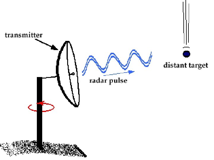
RADAR • RAdio Detection And Ranging • Developed during WWII for detecting enemy aircraft • Active remote sensor – Transmits and receives pulses of E-M radiation – Satellite is passive sensor (receives only) • Numerous applications – Detection/analysis of meteorological phenomena – Defence – Law Enforcement

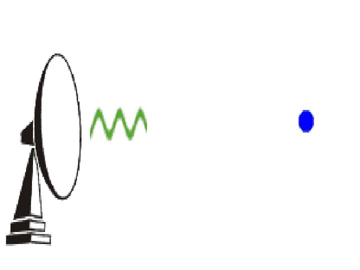
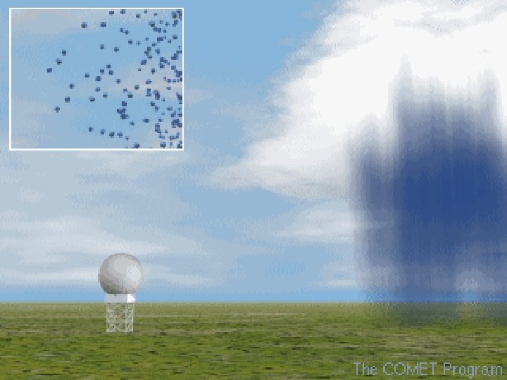
WEATHER SURVEILLANCE RADAR • Transmits very short pulses of radiation – Pencil beam (narrow cone) expands outward – Pulse duration ~ 1 μs (7 seconds per hour) – High transmitted power (~1 megawatt) • ‘Listens’ for returned energy (‘echoes’) – Listening time ~ 1 ms (59: 53 per hour) – Very weak returns (~10 -10 watt) • Transmitted energy is scattered by objects on ground and in atmosphere – Precipitation, terrain, buildings, insects, birds, etc. – Fraction of this scattered energy goes back to radar
")
(http: //www. crh. noaa. gov/mkx/radar/part 1/slide 2. html)
")
BEAM RESOLUTION (http: //www. crh. noaa. gov/mkx/radar/part 1/slide 3. html)

DETERMINING TARGET LOCATION • Three pieces of information – Azimuth angle – Elevation angle – Distance to target • From these data radar can determine exact target location

AZIMUTH ANGLE • Angle of ‘beam’ with respect to north

ELEVATION ANGLE • Angle of ‘beam’ with respect to ground (University of Illinois WW 2010 Project)

DISTANCE TO TARGET • D = c. T/2 • T pulse’s round trip time (University of Illinois WW 2010 Project)
 – Elevation angle constant, varying azimuth")
SCANNING STRATEGIES 1 • Plan Position Indicator (PPI) – Elevation angle constant, varying azimuth angle – Antenna rotates through 360° sweep at constant elevation angle – Allows detection / intensity determination precipitation within given radius from radar – Most commonly seen by general public of
 (University")
PLAN POSITION INDICATOR • Constant elevation angle • Azimuth angle varies (antenna rotates) (University of Illinois WW 2010 Project)

ELEVATION ANGLE CONSIDERATIONS • Radar usually aimed above horizon – minimizes ground clutter – not perfect • Beam gains altitude as it travels away from radar • Radar cannot ‘see’ directly overhead – ‘cone of silence’ – appears as ring of minimal/non-returns around radar, esp. with widespread precipitation • Sample volume increases as beam travels away from radar
 • Red numbers are elevation angles • Note how")
(http: //weather. noaa. gov/radar/radinfo. html) • Red numbers are elevation angles • Note how beam (generally) expands with increasing distance from radar
 • Plan position Indicator (PPI) display presents a plan view")
PLAN POSITION INDICATOR (PPI) • Plan position Indicator (PPI) display presents a plan view of echoes received in polar coordinate (Range (R), Azimuth ( ), Elevation ( )) system. • PPI is intensity modulated (i. e. ) intensity of the echo depends on the strength of the signal received by the receiver of the radar
 • PPI display will have range markers ( at concentric")
PLAN POSITION INDICATOR (PPI) • PPI display will have range markers ( at concentric circles) and topographical underlay so that a visual picture of weather echoes around the radar site can be easily appreciated by the user • It helps to identify the target (both in range and direction from the radar) precisely and hence is quite useful to locate the weather systems, centre of the weather system • With the modern digital radars, the intensity of the signal (echoes) can be displayed in suitable colour schemes for a quick interpretation of the prevailing weather
 -R a -R nge")
PPI display -Azimuth from -true north -Weather echo -Range (km) -R a -R nge ma rke • A typical analogue radar PPI display will look like this, except that the colour of the echo is usually white. an -R a rk er ge m nge ma • But in digital radars, PPI, in addition to the above, displays detailed information about the scan, colours as well. rke r
 -100 km -200 km -400 km -10. 8 km -50")
PLAN POSITION INDICATOR (PPI) -100 km -200 km -400 km -10. 8 km -50 km -3. 0 km -0. 3 km -0. 9 km • Due to the earth’s curvature effect, the height of the scanning beam increases with the range. • Even for a small elevation such as 0. 2 o, the height of the radar beam will be at a height of about 3. 0 km at 200 km range and 10. 8 km at 400 km (after applying corrections for earth’s curvature) whereas it is hardly 0. 3 km at 50 km and 0. 9 km at 100 km

EARTH’S CURVATURE EFFECT -0. 2 o beam do not intercept Cb of 12 km height at 500 km range • Assuming that Cb clouds of 12 km vertical extent are present at 100, 200, 300, 400, 500 km range from a radar, the bottom and middle portion of the Cb clouds upto a range of 300 km and only the top portion at 400 km are intercepted by the radar beam of 0. 2 o elevation. Cb cloud of 12 km height at 500 km range can NOT be probed at 0. 2 o elevation due to the earth’s curvature effect.
 • Interpretation of PPI may have to be done taking")
PLAN POSITION INDICATOR (PPI) • Interpretation of PPI may have to be done taking care that the height of the echo is NOT constant for all ranges for a particular elevation; instead the height of the target is higher at farther ranges and smaller at shorter ranges for the same elevation angle.
 • If the elevations are in steps of the beam")
PLAN POSITION INDICATOR (PPI) • If the elevations are in steps of the beam width of the radar, then the PPI displays at different elevation angles give a total picture of the three dimensional overview of the weather system that has been probed by the radar • However, if there is wide gap between two adjacent elevation angles, then there could be wide gap in data between those two elevations and information on the exact weather system can not be clearly known.
. . 0. 2 o elevation - - n pt -P ho Ec File")
PPI(Z). . 0. 2 o elevation - - n pt -P ho Ec File header indicating year, month, date, time (in UTC) and Product type, scan range -Precipitation echo
. . 0. 2 o elevation -Colour bar code to indicate the intensity of")
PPI(Z). . 0. 2 o elevation -Colour bar code to indicate the intensity of the echoes o. Higher the intensity (d. BZ), higher rate at which it is precipitating. o d. BZ > 20 ordinarily precipitates provided such an echo is from weather clouds. -AZ : Azimuth -EL : Elevation : 0. 2 deg
. . 0. 2 o elevation -Scan Range : 250 km -Scan resolution :")
PPI(Z). . 0. 2 o elevation -Scan Range : 250 km -Scan resolution : 0. 5 km -Display Range : 250 km -Display resolution : 1. 25 km -Sea clutters (identified from the smudge shaped & wave pattern echoes) -Hardware parameters -PW : Pulse width, Short = 1 s -PRF : Pulse Repetition Frequency -(Single PRF 600 Hz is used here) -AS : Antenna Scan rate, 9 deg/s -CC : Clutter Filter -SQI : Signal Quality - Index -CSR : Clutter to Signal Ratio -Log : Log threshold
. . 1. 0 O ELEVATION -Sea clutters appearing at 0. 2 and 1.")
PPI(Z). . 1. 0 O ELEVATION -Sea clutters appearing at 0. 2 and 1. 0 o elevations. -Note : Sea clutters could not be filtered by the clutter filter chosen in this scan
. . 2. 0 O ELEVATION -Note that the weather echoes over land are")
PPI(Z). . 2. 0 O ELEVATION -Note that the weather echoes over land are still seen while the sea clutters vanished at 2. 0 elevation anomalous propagation (AP) is confined to the low level and that too only over ocean.

RADIAL VELOCITY

DOPPLER EFFECT • Based on frequency changes associated with moving objects • E-M energy scattered by hydrometeors moving toward/away from radar cause frequency change • Frequency of return signal compared to transmitted signal frequency radial velocity
")
(http: //www. howstuffworks. com/radar 1. htm)
")
(Williams 1992)
")
(http: //www. crh. noaa. gov/mkx/radar/part 1/slide 13. html)

RADIAL VELOCITY • Hydrometeors moving toward/away from radar – Positive values targets moving away from radar – Negative values targets moving toward radar • Can be used to ascertain large-scale and small-scale flows/phenomena – fronts and other boundaries – mesoscale circulations – microbursts
 • PPI (V) : IT GIVES THE RADIAL VELOCITY")
PLAN POSITION INDICATOR (RADIAL VELOCITY) • PPI (V) : IT GIVES THE RADIAL VELOCITY ON A PPI SCOPE. THE RADIAL VELOCITY TOWARDS RADAR SITE IS TAKEN AS –VE AND AWAY FROM RADAR SITE IS TAKEN AS +VE.
. . 0. 2 O ELEVATION -Warm colours (Red & Yellow) indicate that the")
PPI(V). . 0. 2 O ELEVATION -Warm colours (Red & Yellow) indicate that the hydrometeors are moving away from the radar • Radial velocity over land are due to hydrometeors within the clouds -Cool colours (blue and green) indicate that the hydrometeors are moving towards the radar • Over the east and southern parts of Bay of Bengal, radial velocity of 1 to 5 mps (as high as 9 -11 mps are also seen in the east) are due to sea clutters.
. . 1. 0 O ELEVATION • Weather echoes over the land (west to")
PPI(V). . 1. 0 O ELEVATION • Weather echoes over the land (west to south) appear to move away from the radar. • However, over Bay of Bengal, the radial velocity of 1 to 5 mps are due to the sea clutters. • Note that the sea clutters seen at 200 – 250 km range at 0. 2 o elevation in the east has just diminished / vanished at this (1 o ) elevation.
. . 2. 0 O ELEVATION v Radial velocity due to medium / high")
PPI(V). . 2. 0 O ELEVATION v Radial velocity due to medium / high clouds ( < 10 d. BZ) in the northeast around 150 km range. v. Radial velocity over land are due to weather echoes while the sea clutters in Bay of Bengal has just ceased.

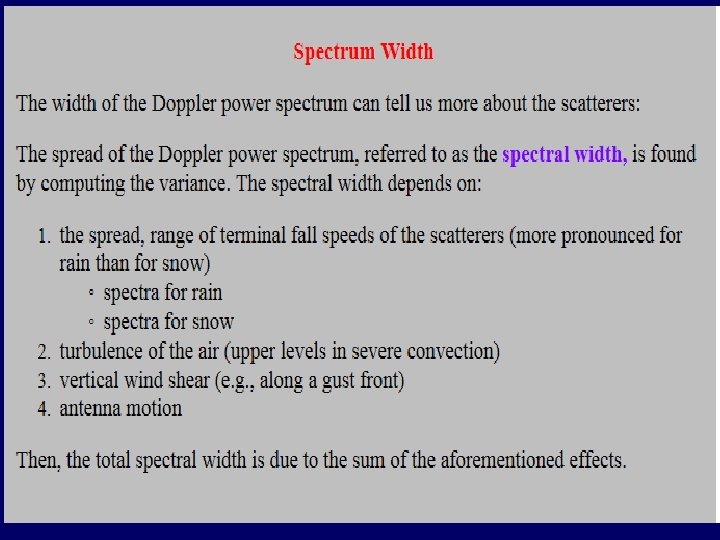
SPECTRUM WIDTH -THE SIGNAL WHICH IS BACK-SCATTERED BY AN ASSEMBLAGE OF MOVING TARGETS CONTAINS INFORMATION ABOUT THEIR RADAR CROSS-SECTION AND RADIAL VELOCITIES. - BY MEANS OF A SUITABLE DATA-PROCESSING SCHEME, IT IS POSSIBLE TO EXTRACT THE BACK-SCATTERED POWER AS A FUNCTION OF DOPPLER SHIFT FREQUENCY. SUCH A FUNCTION IS CALLED DOPPLER SPECTRUM.

 • PPI (W) : IT IS A MEASURE OF")
PLAN POSITION INDICATOR (SPECTRUM WIDTH) • PPI (W) : IT IS A MEASURE OF TURBULENCE AND IT IS OF IMMENSE USE IN NOWCASTING THE OCCURRENCE OF MICROBURST, WIND SHEER • LOW VALUE OF SPECTRUM WIDTH SHOWS UNIFORM WIND FLOW AND HIGH VALUE OF SPECTRUM WIDTH SHOWS TURBULENCE. • A TYPICAL PPI (W) IS SHOWN.
. . 0. 2 O ELEVATION ØHigher spectrum width over land is due to")
PPI(W). . 0. 2 O ELEVATION ØHigher spectrum width over land is due to the precipitating clouds. ØSpectrum width is a measure of turbulence and gives an indication about the movement of hydrometeors within the sample volume. Ø W > 4. 8 mps is indicative of moderate to severe turbulence. -Large W > 3 mps from the sea clutters of large radial velocity. Ø Very minimum spectrum width (<0. 8 mps) over Bay of Bengal are indicative of sea clutters.
. . 1. 0 O ELEVATION o However, W in the sea clutters are")
PPI(W). . 1. 0 O ELEVATION o However, W in the sea clutters are very small in the range 0. 10. 8 mps. -Sea clutters have typical shape. . orientation towards radar. . Smudgy …stretched lengthwise bit with minimum width -W in the precipitating and non-precipitating clouds are more over land
 • When the antenna of a weather")
SCANNING STRATEGIES 2 RANGE HEIGHT INDICTOR (RHI) • When the antenna of a weather radar scans in a particular azimuth with varying elevations (i. e) known as elevation scan, RHI display is used • This display gives information about the height vis-àvis range of the echoes, keeping the radar as the origin • Like PPI, this scope is also intensity modulated
 – Azimuth angle constant – Elevation angle varies")
RHI • Range Height Indicator (RHI) – Azimuth angle constant – Elevation angle varies (horizon to near zenith) – Cross-sectional view of structure of specific storm (University of Illinois WW 2010 Project)
 • Continuity between two adjacent elevations has to be maintained")
RANGE HEIGHT INDICTOR (RHI) • Continuity between two adjacent elevations has to be maintained so that the weather system can be probed without any data gap in between • Here again the curvature effect of the earth plays a significant role in interpretation of the echoes • For a given elevation, the lowest height of the echo at farther ranges will be at a higher height from the ground than that at the nearby range

RHI DISPLAY • A typical analogue radar RHI display will look like this, except that the echo will be in different shades of white / brightness. -Precipitating echoes • But in digital radars, in addition to the above, RHI will have scan details, colour bar code as well.
 -At farther range, the lowest height of the echo intercepted by the")
RHI (Z) -At farther range, the lowest height of the echo intercepted by the radar beam is higher than that at the nearer ranges. -EL : Elevation 0 to 25 deg -AZ : Azimuth of the elevation scan
 -+ve radial velocity indicating updrafts (i. e) hydro-meteors moving away from the radar")
RHI(V) -+ve radial velocity indicating updrafts (i. e) hydro-meteors moving away from the radar (ground) -- ve radial velocity indicating hydro-meteors moving towards ground(radar)
 -Spectrum width is quite low indicating -weak turbulence or mixing within the clouds")
RHI(W) -Spectrum width is quite low indicating -weak turbulence or mixing within the clouds

RADAR PRODUCTS
 • A typical plot of MAX(Z) will be looking like")
DISPLAY OF MAXIMUM (Z) • A typical plot of MAX(Z) will be looking like the one shown below - North -–Height South -Maximum value -of each pixel on -top projection - East – West
 - North – -South -Height -East – -West")
DISPLAY OF MAXIMUM (Z) - North – -South -Height -East – -West

SURFACE RAINFALL INTENSITY • IT IS AN IMAGE OF THE RAINFALL INTENSITY IN A USER SELECTABLE SURFACE LAYER. IT IS CALCULATED BASED ON MARSHALL-PALMER EQUATION Z=ARb WERE R IS THE RAINFALL INTENSITY AND A AND B ARE CONSTANT. THE VALUE OF A & B VARIES FROM SEASON TO SEASON AND PLACE TO PLACE

PRECIPITATION ACCUMULATION • THE PAC PRODUCT IS A SECOND LEVEL PRODUCT. IT TAKES SRI PRODUCTS OF THE SAME TYPE AS INPUT. THE DISPLAY SHOWS THE COLOUR CODED RAINFALL AMOUNT IN (MM) FOR THE DEFINED TIME PERIOD. PRECIPITATION ACCUMULATION ESTIMATION BY THE RADAR CAN BE USEFUL TO WORK OUT WATER INFLOW IN CATCHMENTS, FLOOD FORECASTING IN ALMOST REAL TIME BASIS IN THE ABSENCE OF CONVENTIONAL RAIN GAUGE NETWORK.

POINT RAINFALL TOTAL • THE PRT PRODUCT ALLOWS THE COMPARISON OF RAIN GAUGE DATA WITH CORRESPONDING RADAR DATA. THE RAIN GAUGE MEASURED RAIN INTENSITY VALUES (IN MM/H) ARE DISPLAYED IN HISTOGRAMS. RADAR DATA FROM SRI PRODUCTS ALSO CONTAIN RAIN INTENSITY VALUES AND ARE SHOWN IN SEPARATE HISTOGRAMS.

VERTICAL INTEGRATED LIQUIDS • THE AIM OF THE VIL PRODUCT IS TO GIVE AN INSTANTANEOUS ESTIMATE OF THE WATER CONTENT RESIDING IN AN USERDEFINED ATMOSPHERIC LAYER IN THE ATMOSPHERE. • THIS PRODUCT IS AN EXCELLENT TOOL TO INDICATE THE RAINFALL POTENTIAL OF A SEVERE STORM. THE PRODUCT DATA OUTPUT AND DISPLAY GIVES A SHORT-TERM FORECAST OF PRECIPITATION TO BE EXPECTED SOON, ESPECIALLY IF THE LOWER LAYER BOUNDARY IS CHOSEN ALOFT (1000 M).
 ANALYSES REFLECTIVITY DATA FOR AREAS")
HAIL WARNING PRODUCT • THE HAIL WARNING PRODUCT (HHW) ANALYSES REFLECTIVITY DATA FOR AREAS OF PROBABLE OR VERY PROBABLE HAIL OCCURRENCE. SUCH AREAS ARE INDICATED BY (WARNING) COLOURED AREAS, WHICH CAN BE UNDERLAYED BY REFLECTIVITY DATA. IN CASE OF PROBABLE HAIL OCCURRENCE THE USER IS ALERTED BY THE MESSAGE BOX INDICATOR. THE HHW PRODUCT NEEDS RADAR DATA FROM A VOLUME SCAN (I. E. AT LEAST TWO ELEVATIONS) WITH Z DATA.

GUST FRONTS • Gust Fronts are small lengthy objects with a significant change in radial speed along their short axis.
 PSEUDO CAPPI (PCAPPI) • CAPPI layer display are in the")
CONSTANT ALTITUDE PPI (CAPPI) PSEUDO CAPPI (PCAPPI) • CAPPI layer display are in the form of Cartesian type rather than polar coordinate • From the data obtained in polar coordinate system, data over the Cartesian coordinates (Xi, Yj) are generated for a given height (constant altitude)
 PSEUDO CAPPI (PCAPPI) • CAPPI products are quite useful in")
CONSTANT ALTITUDE PPI (CAPPI) PSEUDO CAPPI (PCAPPI) • CAPPI products are quite useful in cloud physics and precipitation/ hydrometeor studies such as identification of hail stones etc • Only those data that are intercepted for the chosen height from the adjacent elevations are considered for this product. More number of elevations are needed to cover the planetary boundary layer at shorter ranges from the radar.

RADAR EQUATION

TYPES OF RADAR Two main radar types: – Conventional Radar – Doppler Radar

TYPES OF RADAR Mono-static. Same antenna is used for both transmission and reception. Bi-static. Transmitter and its antenna at one location and receiver and its antenna are located at another location separated by a reasonable distance.
. Transmits electromagnetic (EM) radiation continuously and hence signal")
TYPES OF RADAR Continuous Wave (CW). Transmits electromagnetic (EM) radiation continuously and hence signal is received back continuously. Pulsed Radar. Short pulse of EM radiation is transmitted and waits for reasonable duration to receive returned signal. All weather radars are of this type

TYPES OF RADAR Doppler Radar. Based on well known Doppler effect
 30 -300 2, 000 – 4, 000 – 8,")
WAVELENGTH AND APPLICATION Frequency (MHz) 30 -300 2, 000 – 4, 000 – 8, 000 9, 000 -11, 000 12, 000 -40, 000 -220, 000 Wavelength band VHF S C X K Millimeter Wavelength Main purpose / application area 10 -1 m Wind profilers, clear air returns, turbulence and refractive index structure 15. 0 -7. 5 cm Tropical cyclone, severe weather detection, precipitation estimation 7. 5 -3. 75 cm (severe) Weather phenomenon detection, precipitation measurements 3. 3 -2. 7 cm Thunderstorm and associated phenomenon detection weather 2. 5 -0. 75 cm Cloud micro physics, tornado detection, precipitation estimation from attenuation. 7. 5 -1. 30 mm Cloud microphysics, detection ceilometer, tornado
 • Range height indicator (RHI)")
TYPES OF RADAR OUTPUTS • Plan Position Indicator (PPI) • Range height indicator (RHI) • Constant altitude plan position indicator (CAPPI): A horizontal cross-section display of a variable at a specified altitude, produced by interpolation from the volume data. It is used for surveillance and for identification of severe storms. It is also useful for monitoring the weather at specific flight levels for air traffic applications. • Vertically-integrated liquid (VIL) can be displayed, in plan, for any specified layer of the atmosphere. It is an indicator of the intensity of severe storms.

TYPES OF RADAR OUTPUTS • Vertical cross-section: This is a display of a variable above a user-defined surface vector (not necessarily through the radar). It is produced by interpolation from the volume data. • Column maximum: A display, in plan, of the maximum value of a variable above each point of the area being observed; • Echo tops: A display, in plan, of the height of the highest occurrence of a selectable reflectivity contour, obtained by searching in the volume data. It is an indicator of severe weather and hail;

RADAR TO RAINFALL

RADAR TO RAINFALL Z= 6 ΣD Radar reflectivity factor u Signal varies with 6 th power of raindrop diameter u

RADAR TO RAINFALL u R = rainfall rate u a and B are empirical constants u Complicated relationship between Z and R u Adjust Z to R conversions using rain gauge readings

RAINDROP SIZES A B n Rainfall rates are deduced from drop size n Small drops have lower rate than larger drops n Under-estimate at A, over-estimate at B

Z-R RELATIONSHIP • Rainfall is never composed of all drops of same size. So, drop-size distribution cannot be determined and may vary largely for same rate of pptn from one event to other. • Since it is not practical operationally to measure ∑D 6 (dropsize distribution), an empirical formula has been adopted, which relates average values of ∑D 6 with rate of rainfall R. • This formula is called as ‘Z-R relationship’ and gives : - Where, Z is radar reflectivity factor (= ∑D 6) and A & b are two constants.

Z-R RELATIONSHIP • Values of constants ‘A’ & ‘b’ vary considerably for different types of pptn, as well as, for different sizes of raindrops and their distribution in the volume. • Many studies have shown various values of these constants. • Batton listed various values of these. Some of these are: - For Orographic RA/DZ For Stratiform Rain For T’Showers • Generally, value of ‘A’ increases and value of ‘b’ decreases with increasing convective intensity.
")
IMD RADAR NETWORK CDR • A network of 10 S-Band Cyclone Detection Radars (CDR) covering the Indian Coast line. • 06 on East Coast and 04 on West Coast. • Recently replaced existing old generation radars with 04 state-of-art S-Band DWRs at Chennai, Kolkata, Machilipatnam & Visakhapatnam. • Installed one indigenous Doppler Weather Radar at Sriharikota (AP).

CDR

IMD RADAR NETWORK SDR • A network of 12 X - Band Storm Detection Radars (SDR). Dual Purpose Radar • A network of 17 X - Band Dual Purpose (Weather cum Wind Finding) Radar.

SDR & DUAL PURPOSE RADARS
 MOTHALA (NEAR BHUJ)")
DOPPLER WX RADAR IN IAF -AEROSTAT/ AIRSTAR -LOCATION BARNALA(PUNJAB) MOTHALA (NEAR BHUJ)

WEATHER INSTRUMENTS -ONBOARD MET SENSORS -Anemomete r -Barometer -Sonic Anemometer

MST RADAR

HISTORICAL BACKGROUND • Mesospheric Stratospheric Tropospheric RADAR • MST radar a new subject • Came in recent two decades • MST radar technique evolved from work of Woodman and Guillen (1974) pioneering to explore atmospheric dynamics up to a height of about 100 km & develop the MST Radar Technique

MST RADAR • MST radar is a highly sensitive high resolution radar operating typically around 50 MHz • Radars operating at higher frequencies are stratosphere -troposphere (ST) radars. • Observations of the structure and wind fields in the middle atmosphere with unprecedented height and time resolutions

INDIAN MST RADAR • A major MST radar has been established in India as a national faculty of Gadanki near Tirupathi (Geo. 13. 5°N 79. 2°E, Geomag Lat 6. 3°). This radar is highly sensitive, pulse coded, coherent VHF phased array radar operating at 53 MHz with an average power aperture product of 7 X 10⁸ Wm 2.

MST RADAR – A CONCEPT • The gaseous envelope surrounding earth is known as the terrestrial atmosphere. • By virtue of its composition the atmosphere regulates the temperature and provides shielding effect from harmful wavelengths of the solar radiation, thus making the life as the earth possible. • The division of the atmosphere is in the form of spherical shells named as the troposphere, the stratosphere, the mesosphere and thermosphere, and is characterized by the way temperature varies with the height.

MST RADAR – A CONCEPT • Statistical description of atmospheric motions over the earth, their role in transporting the constituents of the atmosphere and the transformation if different forms of energy constitute the subject of atmospheric dynamics and is studied with sophisticated instrumentation systems and analysed using a model of atmospheric general circulation.

MST RADAR – A CONCEPT • The MST radar is a state of art instrument capable of providing estimates of atmospheric parameters with high resolution on a continuous basis which is essential in the study of different dynamical processes in the atmosphere

MST RADAR – A CONCEPT • An important research tool • Investigation of prevailing winds, waves including gravity waves), turbulence, and atmosphere stability & other mesoscale phenomena • A reliable three dimensional model of the atmosphere over the low latitudes improves our understanding of the climate and weather variations


SCATTERING MECHANISMS • Scattering and reflection mechanisms responsible for the ST radar signal return are (a) Turbulent scatter (b) Fresnel (Partial reflection/scatter and (c) Thermal (incoherent or Thomson) scatter –The first two mechanisms provide coherent scatter which results from macroscopic fluctuations in refractive index associated with clear air turbulence (CAT) – The third arises from Thomson scatter by free electrons in the ionosphere and the signal return is characterised by the statistical fluctuations of electron density due to radon thermal motions of electrons and ions

to SCATTERING MECHANISMS • Turbulent Scatter. According scattering from turbulent fluctuations of refractive index, the radar back scattered signal arises from the spatial Fourier component whose wavelength is equal to one half of the radar wavelength λR. • Fresnel (Partial) Reflection and Scattering • Fresnel (Partial) reflection occurs from a sharp vertical gradient in refractive index that if horizontally coherent over a scale greater than a Fresnel zone. • Thomson (Incoherent) Scatter • Thomson Scatter, often referred to as incoherent scatter, is clearly the most potent of the ground based radar techniques to prose the earth’s ionosphere. Recent advances have extended as application to mesosphere

MST RADAR HIGHLIGHTS • Mapping of high resolution vector winds including the detection of strong wind shears particularly in the zonal components • Detection of tropopause and its structure • Detection of turbulent layers with scales of the order of the range resolution of the radar (approx 150 m)
 fluctuations observed in the")
MST RADAR HIGHLIGHTS • Short period (5 to 10 min) fluctuations observed in the horizontal and vertical wind components specially in the height region of 6 to 8 kms which was also the region of strong wind shears. • Measurements of vertical convection • Irregularities in E and F region

MST Radar Technique • Basic System. An. MSTradariscomprised of a high resolution two-dimensional phased array, high power transmitters, with appropriate feed network, T/R switch(es), a phase coherent receiver with quadrature channels, a signal processor consisting of two identical channel of A/D converter, decoder and integrator, a computer interface and a ; mini/super micro computer with essential peripherals and software support.

MST Radar Technique • Antenna Array. An MST radar uses a two-dimensional filled array for both transmission and reception. To effect an improved side lobe suppression, a tapering of the antenna array can be applied by introducing a weighting function to the power fed to the elements or by using unequal element spacing. • The phased antenna array consists of two orthogonal sets, one for each polarization of 1024 threeelement Yagi-Uda antennas arranged in a 32 X 32 matrix over an area of 130 m X 130 m. The array is illuminated in either of the polarization using 32 transmitters of varying power, each feeding a linear sub-array of 32 antennas.

MST Radar Technique • Transmitting System. A total transmitter power of 2. 5 MW (peak) is provided by 32 transmitters ranging in power from 15 KW to 120 KW, each feeding a sub array of 32 Yagis. The input to the transmitter is a low-level (1 mw) pulse -modulated (Coded/uncoded) signal at 53 MHz generated by a mixer which receives as inputs a 5 MHz pulse-modulated signal and an appropriately phase-shifted 48 MHz local oscillator (LO) signal.

MST Radar Technique • Receiver & Signal Processor. The receiver unit consists of a blanking switch, a low-noise amplifier (LNA), and a mixer-pre amplifier for each of the 32 channels. The LNA is a 53 -MHz turred amplifier with a gain of 24 d. B and a band-width of 4 MHz. The output of an LNA is mixed with an appropriately phase shifted 48 MHz LO signal and amplified in a mixer preamplifier having an effective gain of 7 d. B. The IF outputs from the 32 channels are combined and amplified in a broadband modular amplifier with a gain of about 15 d. B.
- Slides: 100