Basic Mechanisms II Engineering System Mechanisms Content Cams

Basic Mechanisms II Engineering System : Mechanisms
")
Content • • Cams Eccentrics Ratchets Inclined plane Crank/Slider Screw (Bearings)

Cam – Specially shaped piece of metal or plastics – Edge/profile of the cam guides the motions of a follower – Cam converts the input motion (rotary/reciprocating) into a reciprocating output motion of the follower.

• Cam motion – One complete rotation of the cam is called a cycle. – Crown : follower is in contact with the highest point of the cam – Heel : lowest part of the follower is in contact – Dwell : when the follower is stationary

– Stroke : the distance between the highest and lowest points on the cam profile

• Types of Cam & Followers Point follower Sliding & oscillating follower Roller follower Angled foot follower

Flat follower Knife follower Edge follower Sliding yoke follower A follower can be kept in contact with a cam by its own weight, or by the forces acting through a lever or linkage, or by a spring

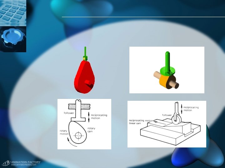
• Profile shapes vs motions – Most cams are designed to have a smooth curved shape so that the motion transmitted to the follower is smooth and without sudden changes. – – Pear-shaped cam Circular cam Heart-shaped cam Uniform acceleration & retardation cam

• Pear-shaped cam – Often used for controlling valve – Follower remains motionless for about half a revolution of the cam – Pear shape is symmetrically, so the period for the rise and fall motion are same

• Circular cam – Eccentric cam – Cam profile is a circle – The center of rotation is offset from the geometric center of the circle – Produce simple harmonic motion

• Heart-shaped – Follower moves with a uniform velocity – For motions needs to be uniform or steady e. g. winding wire evenly on the former of a solenoid

• Uniform acceleration & retardation cam – Follower gains & loses velocity at a constant rate – Used to control the motion of linkages and levers in complex machinery

• Examples of cams – Flat plate cam – Box cam – Swash plate cam – Barrel or cylindrical cam

• Flat plate cam – The edge is shaped and the profile can be used to guide the motion of a follower – Used in automatic machine tool e. g. cutting tool on automatic lathes

• Box cam – A groove can be milled in the face of cam discs. – As the cam rotates, a follower located in the groove has its motion guided by the groove. – e. g. winding mechanisms of a fishing reel

• Swash plate cam – A disc is fixed to a rotating shaft and the disc is attached an angle to the axis of rotation of the shaft – e. g. pump mechanisms

• Cylindrical or barrel cam – Consisting of a rotating cylinder with a helical (screw shaped) groove in its curved surface – A follower with a tapered roller end is located in the groove – As cylinder turns, the follower moves in straight line parallel to the axis of the rotating cam – e. g. to guide thread on sewing machines

Eccentrics • A circular cam is often called an eccentric cam • The axis of rotation of the cam is offset from the geometric center of the circular disc • Transmit simple harmonic motion to the follower

• Eccentric cam is used on cam shaft of a motorcar to drive the petrol pump

Ratchet – A wheel with sawshaped teeth round its rim is called ratchet – The ratchet wheel usually engages with a tooth-shaped lever called pawl – The purpose of ratchet & pawl is to allow rotation in one direction only and prevent rotation in the opposite direction

• A ratchet wheel can also be used to arrest motion – e. g. A fishing reel uses a ratchet to prevent the fishing line unwinding

– The ratchet wheel and pawl can be used in a different manner. – The pawl is designed to rotate about he same center as the ratchet wheel. – An oscillating input motion is given to the pawl and it transmits motion to the ratchet wheel. – The ratchet wheel is rotated in steps pf one or more teeth by each input of motion from the pawl.

Inclined Plane • Inclined plane is a sloping surface used to gain mechanical advantage when raising a load

Exercise Calculate the velocity ratio & mechanical advantage of the inclined plane

• Effort=weight x sinθ=mgsinθ=h/s So effort E=mgh/s • Mechanical advantage =Load/effort=s/h • Velocity ratio =distance moved by effort distance moved by load =s/h

• Wedge – Wedge is two inclined planes back-to-back – A wedge is often used to raise a heavy load through a small distance – To cleave apart the fibers of material

Screw Thread • A disguised form of inclined plane? • Screw thread is a helical or spiral groove cut in the surface of a cylindrical shaft. • As the thread winds round the shaft • Screw is used to transmit motion and force
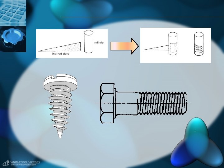

• Screw thread terms – Crown : Top of the thread – Pitch : Distance between two adjacent crowns – Lead : Distance moving in one complete revolution of the screw shaft. – Thread angle – Major/minor diameter

– A screw made with one helix or thread running around is single screw thread. – A screw with more than one thread running round it is known as multiple start thread. Multiple start threads transmit more rapid motion.

• Screw thread forms – V-thread : vee-shaped groove of the thread form • Used in threaded or tapped hole or with a nut • Fastening devices, e. g. set screws, nut & bolts (because large amount of friction between the sides of the screw and nut)
 British Association thread (BA) ISO metric thread")
British Standard Whitworth Thread (BSW) British Association thread (BA) ISO metric thread

– Square thread • Gets its name from the profile shape of the thread form • Used for moving parts of machines e. g. valve spindle, lifting jack • Not as strong as the corresponding v-thread but friction is less.

• Screw applications – Cramps & vice • Use of square screw thread to tighten jaw which hold a workpiece firmly G cramp Metalwork vice

– Book binding press • Square thread is used to transmit the force downward to squeeze.

• Screw jack

Crank • Crank is a device by which torque can be applied to a shaft Crank wheel Crank handle windlass

– Crankshaft • A crank handle can be incorporated into a shaft. A shaft with several cranks in it is called a crankshaft

• Crank / slider mechanisms – The crank / slider mechanisms consists of a rotating crank which is connected to a slider by a connecting rod.

– The mechanism can be used to convert rotary motion into reciprocating motion or vice versa.

• Crank / slider mechanisms Application Fabric tester
- Slides: 42