Basic Hydraulics Hydr 1305 Hydraulic Schematics LEGEND Many

Basic Hydraulics Hydr 1305 Hydraulic Schematics

LEGEND • Many of the hydraulic circuits do not show the pump, reservoir, and pump pressure relief valve. • Ports indicated by "P" are the source of pressurized hydraulic fluid. § The hydraulic fluid pressure is controlled by a pump pressure relief valve RESERVOIR & ENCLOSURE • Ports indicated by "T" lead back to the reservoir and may have the reservoir symbol: . • Ports such as "A", B, 1, 2, etc. are identified to differentiate one PUMP PRESSURE port from another. RELIEF VALVE PUMP & MOTOR

Hydraulic Schematics RESTRICTED FLOW FREE FLOW CONTROL VALVE SINGLE ACTING CYLINDER • In the 3 -2 valve the spring positions the control valve in its normal position; the piston is to its extreme right position. • When the manual push button is depressed fluid is applied to the cylinder at a rate determined by the flow control valve orifice. • The piston then moves to its extreme left position. P T • When the button is released, fluid flows back to the reservoir with no restriction and the piston moves back to the right at a rate determined by the spring tension.

Hydraulic Schematics • The cylinder is operated by one of two 3 -2 control valves via the shuttle valve (OR function). • Application: cylinder can be operated automatically with B control valve (cam follower) or manually with the push button A control valve. "OR" FUNCTION A P T B P T

Hydraulic Schematics "AND" FUNCTION A B T P T • Both control valves must be pressed for the cylinder to operate (AND function). • Safety application: both hands must be used to hold the pushbuttons in for a sheet metal press to operate. • Using both hands prevents the operator's hands from being put in harms way.

Hydraulic Schematics "NOT" FUNCTION #1 • As shown control valve B is applying fluid to cylinder #1 and control valve A has cylinder #2 drained to the reservoir. • When control valve A is pressed: • Fluid is applied to the pilot of valve B causing valve B to drain fluid from the cylinder and move the piston to the right. • Fluid is also applied to cylinder #2 causing it to move to the left. B A • When valve A push button is released: P T #2 • Valve B goes back to its position as shown and fluid flows into #1 cylinder moving it back to the left. • Valve A drains cylinder #2 moving it back to the right.

Hydraulic Schematics SIGNAL DELAY B OFF DELAY P ON DELAY A P T T • This arrangement is to provide a delay "off" signal (as shown) or a delay "on" signal. • When valve A state changes by the cam follower, pilot operated control valve B is immediately loaded which moves the piston to the right. • When valve A is released, valve B is unloaded after a period of time depending on how fast the fluid bleeds through the orifice. • When valve B unloads after the delay it drains fluid from the cylinder and the piston moves back to the left.

Hydraulic Schematics DOUBLE ACTING CYLINDER • A 4 -2 control valve is used to position a double acting cylinder. • The valve has two positions and stays in the position it was last placed. C 1 C 2 A T B P • The flow control valves limit how fast the piston moves in both directions. § If the pushbutton is pressed, fluid flows to port C 1 of the cylinder from port A of the valve; there is no delay. § But fluid flowing from cylinder port C 2 to port A on the valve is restricted which slows the piston's rate of travel.

Hydraulic Schematics DOUBLE ACTING CYLINDER C 1 C 2 A T B P • The reason the flow control valves are used instead of orifices only: § Since the orifices interact with each other it would be very difficult to accurately match their amount of flow. • Otherwise the orifice most restricted would always be in control. § Additionally the flow control valves provide the capability to adjust the extension and retraction speeds separately as needed for the intended application.

Hydraulic Schematics FLIP/FLOP FUNCTION C 1 C 2 A B T P P T • This arrangement allows the cylinder to stay in place from either remotely located control valves 1 or 2. • As shown valve 3 is unloaded and holding the piston to the left. • When valve 1 pushbutton is pressed, valve 3 is loaded at P-1 and the piston moves to the right. • When valve 1 push button is released the detent at P-1 holds valve 3 in the left box position. • When valve 2 pushbutton is pressed, valve 3 is loaded at P-2 and the piston travels back to the left position. • Again, the detent hold valve 3 in place until valve 1 is pressed again.

Hydraulic Schematics – Two Station Cylinder Operation Description of Operation • A cylinder can be extended from one station and then retracted from the other station. • If station A extends the STATION A piston rod, station B can retract the piston rod. • If station B extends the piston rod, station A can retract the piston rod. • But a piston rod can only be extended or retracted by the other station's control valve. STATION B

Hydraulic Schematics – Two Station Cylinder Operation as shown: 1. Fluid is applied to port _____ of the cylinder. 2. ______ of the cylinder drains to the reservoir. 3. The cylinder is in its ______ position.

Hydraulic Schematics – Two Station Cylinder Operation as shown: C-2 of the cylinder. 1. Fluid is applied to port _____ C-1 of the cylinder drains to the reservoir. 2. ______ LEFT position. 3. The cylinder is in its ______

Hydraulic Schematics – Two Station Cylinder Operation 1. If CV-1 is pressed and released ______ of PV is loaded and fluid flows to port ______ of the cylinder. 2. ______ of the cylinder drains to the reservoir. 3. The cylinder is now in its ______ position.

Hydraulic Schematics – Two Station Cylinder Operation PI-1 of PV is loaded and fluid flows 1. If CV-1 is pressed and released ______ C-1 of the cylinder. to port ______ C-2 of the cylinder drains to the reservoir. 2. ______ RIGHT position. 3. The cylinder is now in its ______

Hydraulic Schematics – Two Station Cylinder Operation 1. If CV-2 is pressed and released ______ of PV is loaded and fluid flows to port ______ of the cylinder. 2. ______ of the cylinder drains to the reservoir. 3. The cylinder is now in its ______ position.

Hydraulic Schematics – Two Station Cylinder Operation PI-2 of PV is loaded and fluid flows 1. If CV-2 is pressed and released ______ C-2 of the cylinder. to port ______ C-1 of the cylinder drains to the reservoir. 2. ______ LEFT position. 3. The cylinder is now in its ______

Hydraulic Schematics – Ash Hopper System Description of Operation: • When ash level is between LEV-S high level (H) and low level (L), the hopper is filling and ash is not being pulled. • Gate-1 is open to allow ash to fall into the hopper from the ash silo. • Gate-2 is closed to prevent ash from flowing into the vacuum pump. • The vacuum pump is not running. • When ash level rises to the high level (H), LEV-S contact closes: • Gate-1 closes to prevent vacuum from being lost in the hopper. • Gate-2 opens to allow ash to be pulled. • The vacuum pump starts and pulls ash from the hopper. • When the level drops to the low level (L), LEV-S contact opens: • Gate-1 opens to allow ash to fall into the hopper from the ash silo. • Gate-2 closes to prevent ash from flowing into the vacuum pump. • The vacuum pump stops running.
 \"FOR GATE 1\"")
Hydraulic Schematics – Ash Hopper System ASH SILO CYLINDER 1 (CYL-1) "FOR GATE 1" MECHANICAL HYDRAULIC VALVE (M-V) "OPENS GATE 2" CLOSES / OPENS H ASH HOPPER CYLINDER 2 (CYL-2) "FOR GATE 2" OPENS / CLOSES L LEVEL SWITCH (LEV-S) STARTS THE ASH PULLING SEQUENCE @ HIGH LEVEL & REVERSES THE ASH PULLING SEQUENCE @ LOW LEVEL LIMIT SWITCH (LIM-S) "STARTS THE VACUUM PUMP" VACUUM PUMP "PULLS ASH"

Hydraulic Schematics – Ash Hopper System
: Hydraulic Schematics – Ash Hopper System")
As shown (Level Between H & L Levels): Hydraulic Schematics – Ash Hopper System 1. Fluid drains from ports ______ to ______ of valve A, from ports ______ to ______ of valve B, and from cylinder 1. 2. Fluid is applied to ports ______ to ______ of M-V and to cylinder 2. 3. Gate 1 is (open or closed) and gate 2 is (open or closed)? 4. The vacuum pump is (running or not running)?
: Hydraulic Schematics – Ash Hopper System")
As shown (Level Between H & L Levels): Hydraulic Schematics – Ash Hopper System A T A 1. Fluid drains from ports ______ to ______ of valve A, from ports ______ to T ______ of valve B, and from cylinder 1. P A 2. Fluid is applied to ports ______ to ______ of M-V and to cylinder 2. 3. Gate 1 is (open or closed) and gate 2 is (open or closed)? 4. The vacuum pump is (running or not running)?
: Hydraulic Schematics – Ash Hopper System 1. When level reaches")
Operation (Reaches High Level): Hydraulic Schematics – Ash Hopper System 1. When level reaches the H level valve A solenoid valve (energizes or deenergizes) and fluid flows through ports ______ to ______ of valve A, ports ______ to ______ of valve B, and to cylinder 1. 2. Gate 1 (opens or closes) and (actuates or un-actuates) M-V. 3. Fluid drains from ports ______ to ______ of M-V, and from cylinder 2. 4. Gate 2 (opens or closes) and (actuates or un-actuates) LIM-S. 5. The vacuum pump (starts or stops), and the indicator light (illuminates or goes out), 6. The vacuum pump pulls ash from the hopper.
: Hydraulic Schematics – Ash Hopper System 1. When level reaches")
Operation (Reaches High Level): Hydraulic Schematics – Ash Hopper System 1. When level reaches the H level valve A solenoid valve (energizes or de. P A of valve A, ports energizes) and fluid flows through ports ______ to ______ of valve B, and to cylinder 1. T A 2. Gate 1 (opens or closes) and (actuates or un-actuates) M-V. A T 3. Fluid drains from ports ______ to ______ of M-V, and from cylinder 2. 4. Gate 2 (opens or closes) and (actuates or un-actuates) LIM-S. 5. The vacuum pump (starts or stops), and the indicator light (illuminates or goes out), 6. The vacuum pump pulls ash from the hopper.
 Hydraulic Schematics – Ash Hopper System 1. When level reaches")
Operation: (Reaches Low Level) Hydraulic Schematics – Ash Hopper System 1. When level reaches the L level valve A solenoid valve (energizes or de -energizes) and fluid drains from ports ______ to ______ of valve A, from ports ______ to ______ of valve B, and from cylinder 1. 2. Gate 1 (opens or closes) and (actuates or un-actuates) M-V. 3. Fluid is applied to ports ______ to ______ of M-V and to cylinder 2. 4. Gate 2 (opens or closes) and (actuates or un-actuates) LIM-S. 5. The vacuum pump (starts or stops) and the indicator light (illuminates or goes out). 6. The vacuum pump stops pulling ash from the hopper; the hopper can fill again.
 Hydraulic Schematics – Ash Hopper System 1. When level reaches")
Operation: (Reaches Low Level) Hydraulic Schematics – Ash Hopper System 1. When level reaches the L level valve A solenoid valve (energizes or de A to ______ T of valve A, from -energizes) and fluid drains from ports ______ A T ports ______ to ______ of valve B, and from cylinder 1. 2. Gate 1 (opens or closes) and (actuates or un-actuates) M-V. P A 3. Fluid is applied to ports ______ to ______ of M-V and to cylinder 2. 4. Gate 2 (opens or closes) and (actuates or un-actuates) LIM-S. 5. The vacuum pump (starts or stops) and the indicator light (illuminates or goes out). 6. The vacuum pump stops pulling ash from the hopper; the hopper can fill again.
 Hydraulic Schematics – Ash Hopper System 1. When the operator")
Manual operation (Pull Ash) Hydraulic Schematics – Ash Hopper System 1. When the operator pushes valve C button down, fluid flows from port ____ to ____ of valve C. 2. Fluid flows to the pilot of valve B (loads it or un-loads it), and fluid flows through valve B ports _____to ____, and to cylinder 1. 3. Gate 1 (opens or closes) and (actuates or un-actuates) M-V. 4. Fluid drains from ports ______ to _____ of M-V, and from cylinder 2. 5. Gate 2 (opens or closes) and (actuates or un-actuates) LIM-S. 6. The vacuum pump (starts or stops) and the indicator light (illuminates or goes out).
 Hydraulic Schematics – Ash Hopper System 1. When the operator")
Manual operation (Pull Ash) Hydraulic Schematics – Ash Hopper System 1. When the operator pushes valve C button down, fluid flows from port P to ____ A of valve C. ____ 2. Fluid flows to the pilot of valve B (loads it or un-loads it), and fluid flows P A through valve B ports _____to ____, and to cylinder 1. 3. Gate 1 (opens or closes) and (actuates or un-actuates) M-V. 4. Fluid drains from A T ports ______ to _____ of M-V, and from cylinder 2. 5. Gate 2 (opens or closes) and (actuates or un-actuates) LIM-S. 6. The vacuum pump (starts or stops) and the indicator light (illuminates or goes out).
 Hydraulic Schematics – Ash Hopper System 1. When the")
Manual operation (Stop Pulling Ash) Hydraulic Schematics – Ash Hopper System 1. When the operator pulls out valve C button, fluid drains from ports ______ to ______ of valve C, and (loads or un-loads) valve B. 2. Fluid drains from cylinder 1 via ports ______ to ______ of valve B and from ______ to ______ of valve A. 3. Gate 1 (opens or closes) and (actuates or un-actuates) M-V. 4. Fluid is applied to ports ______ to ______ of M-V and to cylinder 2. 5. Gate 2 (opens or closes) and (actuates or un-actuates) LIM-S. 6. The vacuum pump (starts or stops) and the indicator light (illuminates or goes out).
 Hydraulic Schematics – Ash Hopper System 1. When the")
Manual operation (Stop Pulling Ash) Hydraulic Schematics – Ash Hopper System 1. When the operator pulls out valve C button, fluid drains from ports ______ A T to ______ of valve C, and (loads or un-loads) valve B. A T 2. Fluid drains from cylinder 1 via ports ______ to ______ of valve B and A T from ______ to ______ of valve A. 3. Gate 1 (opens or closes) and (actuates or un-actuates) M-V. 4. Fluid is applied to P A ports ______ to ______ of M-V and to cylinder 2. 5. Gate 2 (opens or closes) and (actuates or un-actuates) LIM-S. 6. The vacuum pump (starts or stops) and the indicator light (illuminates or goes out).

Hydraulic Schematics Flat Metal Stock Bender Description of Operation: The anvil and cylinder are designed to bend 2 inch wide by 1/2 inch steel to 900. • To keep the operator's hands away from the bender, both S 1 and S 2 must be pressed and held in at the same time to extend the cylinder. • The bend must be completed before the operator can retract the cylinder. • V 1 and V 2 are "dual pressure valves" that require pressure on both inputs to allow fluid to flow (this is a new symbol). • L 1 is a mechanically operated control valve that actuates at the end of the piston stroke; when the bend has been completed. • F 2 controls the rate that the piston extends to help prevent fracturing of the metal.

Hydraulic Schematics - Flat Metal Stock Bender

Hydraulic Schematics Flat Metal Stock Bender As shown condition: 1. V 3 is shown in it's position after V 3 B pilot was pressurized. 2. CYL is shown retracted. 3. L 1 is shown with CYL in the retracted position.

Operation: 1. Hydraulic Schematics Flat Metal Stock Bender Both ____ and ____ are depressed for fluid to flow through V 1. 2. V 3 is loaded at ____. 3. Fluid flows to C 1 via ports ____ to ____ of V 3 and drains from C 2 via ports ____ to ____ of V 3 at a rate determined by ____. 4. At the end of the CYL piston stroke, ____ actuates and fluid flows from ports ____ to ____ of L 1, and to ____ of V 2. 5. The operator pushes the retract button, S 3, which pressurizes ____ resulting in fluid flowing through ____. 6. V 3 is loaded at ____. 7. Fluid flows to C 2 via ports ____ to ____ of V 3 with no delay by ____, and drains from C 1 via ports ____ to ____ of V 3. 8. The system is back to the state as shown and ready for the operator to bend another piece of metal.

Operation: 1. Hydraulic Schematics Flat Metal Stock Bender S 1 and ____ S 2 are depressed for fluid to flow through V 1. Both ____ V 3 A 2. V 3 is loaded at ____. P 1 3. Fluid flows to C 1 via ports ____ to ____ of V 3 and drains from C 2 2 to ____ T of V 3 at a rate determined by ____. F 1 via ports ____ L 1 actuates and fluid flows 4. At the end of the CYL piston stroke, ____ V 2 B of V 2. from ports ____ P to ____ 1 of L 1, and to ____ 5. The operator pushes the retract button, S 3, which pressurizes V 2 A resulting in fluid flowing through ____. V 2 ____ V 3 B 6. V 3 is loaded at ____. P to ____ 2 of V 3 with no delay by 7. Fluid flows to C 2 via ports ____ F 1 and drains from C 1 via ports ____, 1 to ____ T of V 3. 8. The system is back to the state as shown and ready for the operator to bend another piece of metal.

Hydraulic Schematics – Quarry Stone Sieve Description of Operation: Quarry stones are fed from a crushing machine via a feeder conveyor belt to two vibrating sieves. • Sieve #1 is reciprocated back and forth by CYL 1 to sort out smaller stones. • The smaller stones drop on to Belt 1. • Sieve #2 is reciprocated back and forth by CYL 2 to sorts out larger stones. • The larger stones drop on to Belt 2. • Any stones remaining on Sieve #2 shake off onto Belt 3. • CYL 3 picks up and drops the sieves repeatedly to unclog the sieves. • A pressure regulator (REG) controls cylinder fluid pressure to control how fast the pistons move, thus how fast the sieves shake back and forth. • The greater the pressure the faster the sieves will shake.
 is")
Hydraulic Schematics – Quarry Stone Sieve As shown condition: 1. Regulated pressure (REG) is present in CYL 1 and CYL 2 to position them as shown. 2. CYL 1 is retracted. 3. CL 2 is extended. 4. L 1 is shown with CYL 1 in the retracted position. 5. L 2 is shown with CYL 2 in the position. extended
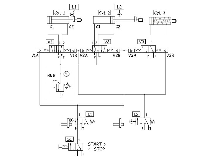

Operation: Hydraulic Schematics – Quarry Stone Sieve 1. The operator places S 1 in the Start position and fluid flows from ports ____to ____. 2. Fluid flows through L 1 and loads V 1 at ____, V 2 at ____, and V 3 at ____. 3. Fluid flows from port ____ to ____ of V 3 and V 3 lifts both sieves. 4. Fluid at REG pressure flows from ports ____ to ____ of V 1 and drains from ports ____ to ____ of V 1, and CYL 1 (extends, retracts). 5. Fluid at REG pressure flows from ports ____ to ____ of V 2 and drains from ports ____ to ____ of V 2, and CYL 2 (extends, retracts). 6. When CYL 2 retracts all the way it actuates L 2 and fluid flows through L 2 which loads V 1 at _____, V 2 at ____, and V 3 at ____. 7. Fluid flows from port ____ to ____ of V 3 and V 3 drops both sieves. 8. Fluid at REG pressure flows from ports ____ to ____ of V 1 and drains from ports ____ to ____ of V 1, and CYL 1 (extends, retracts). 9. Fluid at REG pressure flows from ports ____ to ____ of V 2 and drains from ports ____ to ____ of V 2, and CYL 2 (extends, retracts). 10. Shaking of and lifting and dropping of sieves continues until S 1 is placed in the Stop position.

Operation: Hydraulic Schematics – Quarry Stone Sieve 1. The operator places S 1 in the Start position and fluid flows from ports P 1 ____to ____. 2. V 1 A V 2 at ____, V 2 B and V 3 at ____. V 3 A Fluid flows through L 1 and loads V 1 at ____, 3. P to ____ 1 of V 3 and V 3 lifts both sieves. Fluid flows from port ____ 4. Fluid at REG pressure flows from ports ____ P to ____ 1 of V 1 and drains from 2 to ____ T of V 1, and CYL 1 (extends, retracts). ports ____ 5. Fluid at REG pressure flows from ports ____ P to ____ 2 of V 2 and drains from 1 to ____ T of V 2, and CYL 2 (extends, retracts). ports ____ 6. When CYL 2 retracts all the way it actuates L 2 and fluid flows through L 2 V 1 B V 2 at ____, V 2 A and V 3 at ____. V 3 B which loads V 1 at _____, 7. Fluid flows from port ____ to ____ of V 3 and V 3 drops both sieves. 1 T 8. Fluid at REG pressure flows from ports ____ P to ____ 2 of V 1 and drains from 1 to ____ T of V 1, and CYL 1 (extends, retracts). ports ____ 9. P to ____ 1 of V 2 and drains from Fluid at REG pressure flows from ports ____ 2 to ____ T of V 2, and CYL 2 (extends, retracts). ports ____ 10. Shaking of and lifting and dropping of sieves continues until S 1 is placed in the Stop position.

Hydraulic Schematics – Automatic Ball Bearing Feeding System Description of Operation: The automatic feeding system provides a continuous supply of ball bearings to a bearing assembly machine. • The double acting cylinder periodically extends and retracts to push the ball bearings into the receiver of the bearing assembly machine. • Operator controlled S 1 starts and stops the automatic feeding system. • V 1 is a dual pressure valve that requires pressure on both of its inputs to allow fluid to flow to pilot operated V 2. • L 1 and L 2 are mechanically operated control valves that cause the piston to initiate the extension and retraction of the piston when it reaches its end of stroke. • Flow control valves (F 1, F 2, and F 3) are used as time delays because the bearing assembly machine requires that the ball bearings be delivered in a timed manner.

Hydraulic Schematics – Automatic Ball Bearing Feeding System As shown condition: 1. V 2 is shown with neither of its pilots pressurized. 2. CYL is shown retracted. 3. L 1 and L 2 are both shown with CYL retracted. Timing: 1. F 1 throttles fluid to CYL to provide. 04 second retract time. 2. F 2 throttles exhaust fluid to provide. 06 second extend time. 3. F 3 throttles fluid to V 3 to provide a 1. 0 second delay time.

Automatic Ball Bearing Feeding System

Start sequence operation: 1. S 1 is moved to Start and fluid flows to _____. 2. Fluid flows through V 1 because both ports are (pressurized, vented). 3. V 2 is loaded at port _____ and fluid flows from port _____ to _____ of V 2. 4. Fluid flows to _____ with no delay via F 1. 5. Fluid drains from C 2 via V 2 ports ____ to _____at a rate determined by ___ resulting in a time to full extension of ___ second. 6. When the piston rod extends and actuates L 2, L 2 loads _____ after _____ second via F 3. 7. V 3 loads _____ at _____ and fluid flows to _____ with no delay via F 2. 8. Fluid drains from C 1 via V 2 ports ____ to ____ at a rate determined by ___ resulting in a time to full retraction of ___ second. 9. When the piston rod actuates L 1, L 1 load _____ at _____, and fluid again flows to _____. 10. The sequence continually repeats itself until S 1 is placed in the _____ position.

Start sequence operation: 1. V 1 A S 1 is moved to Start and fluid flows to _____. Hydraulic Schematics – Automatic Ball Bearing Feeding System 2. Fluid flows through V 1 because both ports are (pressurized, vented). V 2 A and fluid flows from port _____ P 1 of 3. V 2 is loaded at port _____ to _____ V 2. C 1 with no delay via F 1. 4. Fluid flows to _____ 2 to _____at E 5. Fluid drains from C 2 via V 2 ports ____ a rate determined by. 06 second. F 2 resulting in a time to full extension of ___ V 3 after 6. When the piston rod extends and actuates L 2, L 2 loads _____ 1. 0 second via F 3. _____ V 3 V 2 B and fluid flows to _____ C 2 with no delay via F 2. 7. V 3 loads _____ at _____ 8. Fluid drains from C 1 via V 2 ports ____ to ____ 1 E at a rate determined by. 06 second. ___ F 1 resulting in a time to full retraction of ___ V 1 B and fluid again 9. When the piston rod actuates L 1, L 1 load _____ at _____, flows to _____. C 1 Stop 10. The sequence continually repeats itself until S 1 is placed in the _____ position.
- Slides: 45