Basic Forces of Flight and Control Surfaces Objectives

Basic Forces of Flight and Control Surfaces

Objectives By the end of this lesson, you will: • Recall the four forces acting on an aircraft in flight. – Be able to explain Bernoulli’s Principle in terms of lift. • Be able to apply proper actions to recover from a Stall • Compare and contrast Induced Drag and Parasite Drag. • Be familiar with the basic parts of an airplane • Flight Simulation: Apply basic flight knowledge to successfully accomplish the objectives in the “First Flight” simulation tutorial.

Forces of Flight

Bernoulli's principle: Lift As a wing passes through the air, its shape makes the air travel farther distance over the top of the wing than beneath it. This creates a higher speed and lower pressure above the wing than beneath it. The pressure difference causes the wing to push upwards and lift is created. Lift is the force acting perpendicular (at right angles) to the direction of flight. In level flight, lift created by the airplane’s wing is equal to the weight of the airplane.

Stalls • A wing “stalls” when the airplane’s angle of attack (the angle between the airplane and the direction of flight) is too great. • This often occurs when the airplane’s speed is too slow to produce sufficient lift, however an airplane can stall at any airspeed or attitude. • To recover from a stall, lower the nose and add power stalled wing

Drag • Induced drag. The drag force generated in the production of lift, caused by the downflow or downwash of the airstream passing over the wing

Drag

Drag • Parasite drag. Drag caused by the friction of air moving over the aircraft structure. Which aircraft produces more parasite drag?

a TOTAL drag… Realize that the total force of drag acting on an aircraft is the sum of induced and parasite drag.

Airplane Parts • All planes have essentially the same basic parts. • They just get bigger as the size of the airplane increases.
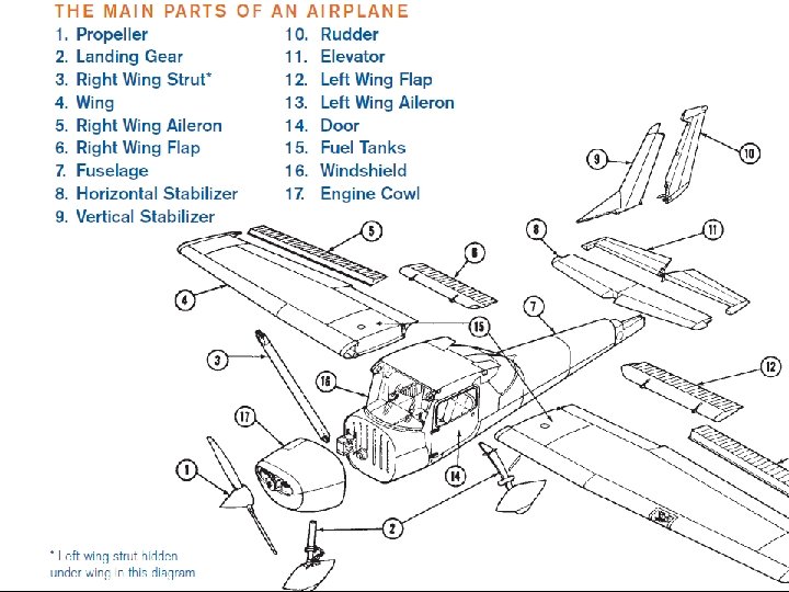

Airplane Parts X-Stream Science - "Parts of an Airplane"

Three Axes of Flight

Three Axes of Flight

Parts That Make the Airplane Fly • Propeller • Wings

Propeller – A propeller is a rotating blade on the front of the airplane. The engine turns the propeller, which pulls the airplane through the air. (Thrust)

Propeller

Wings – Wings are the parts of airplanes that provide lift. They also support the entire weight of the aircraft and its contents while in flight.

Airplane wings generate lift. Low-wing High-wing

CONTROLLING DIRECTION OF FLIGHT. • Ailerons • Elevator • Rudder

Ailerons – Ailerons are the movable sections on an outer edge of an airplane’s wings. • They move in opposite directions (when one goes up, the other goes down). • They are used in making turns by controlling movement along the longitudinal axis (roll)

Ailerons on the rear edge of the wings tilt the wings for a turn or “bank. ” Left turn Right turn Left turn

Elevator – The elevator is the movable, horizontal section of the tail that causes the airplane to climb and descend. • When the elevator moves one direction, the nose moves in the same direction (up or down). • This movement is along the lateral axis (pitch)
 moves up (or down) to force the nose of")
The elevator (on horizontal stabilizer) moves up (or down) to force the nose of the airplane up (or down. )

Rudder – The rudder is the movable, vertical section of the tail • Controls lateral (side-to-side) movement along the vertical axis (Yaw) • When the rudder moves in one direction, the aircraft nose moves the same direction.
 moves the airplane’s nose left or right, helping")
The rudder (on the vertical stabilizer) moves the airplane’s nose left or right, helping it turn. Push left rudder pedal and the plane turns left Push right rudder pedal and the plane turns right

Secondary Flight Controls • Flaps • Trim Tabs • Spoilers/Speed Brakes

Flaps –The movable sections of an airplane’s wings that are closest to the fuselage. They move in the same direction on both wings at the same time, and, by creating drag and lift, enable the airplane to fly more slowly.

Flaps on the wings change the shape of the wing to provide more lift and drag. This allows the airplane to fly slower. Flaps down

Trim Tabs • Trim tabs relieve the pilot of the need to maintain constant pressure on the flight controls • They aerodynamically assist with movement and positioning of the flight control surface they are attached. • Common types of trim systems include elevator, aileron and rudder trim

Spoilers • Spoilers: High-drag devices on the upper surface of the wing designed to decrease or “spoil” lift • Used to control descent rate and speed, reduce landing distance and may be rigged to aid in roll control

Speed Brakes • Speed Brakes: High-drag devices used to control descent rate and speed and reduce landing distance but do not directly affect lift.

Other Main Parts • Fuselage • Cockpit • Landing Gear

Fuselage – The fuselage is the central body of an airplane, designed to accommodate the pilot/crew and the passengers and/or cargo.

The body of an airplane is called the fuselage.

Cockpit – The space within the fuselage where the pilot sits and controls the airplane.

The flight controls and instrument panel are in the front of the cockpit.

Landing Gear – The landing gear is underneath the airplane and supports it while on the ground. The landing gear usually has two main wheels and a nose or tail wheel. May include floats, skis, pontoons or skids.

Powerplants • An aircraft engine, or powerplant, produces thrust to propel an aircraft – Reciprocating engines and turboprop engines work in combination with a propeller to produce thrust • Note - Helicopter engines work in conjunction with rotor blades to produce both lift and thrust – Turbojet and turbofan engines produce thrust by increasing the velocity of air flowing through the engine

Reciprocating Engines • Older aircraft and most modern small aircraft have reciprocating engines. • The name is derived from the back-andforth, or reciprocating, movement of the pistons

Turbine or Jet Engines • All jet engines work on the same principle. – The engine takes air in at the front with a fan. – A compressor raises the pressure of the air. – The compressed air is then sprayed with fuel and an electric spark lights the mixture. – The burning gases expand blast out through the nozzle, at the back of the engine.

Turbine or Jet Engines • Turbine engines are classified according to the type of compressors they use. – There are three types of compressors: centrifugal flow, axial flow, and centrifugal-axial flow. Centrifugal Flow Axial Flow

Break Time? Take Five, Everybody!


Primary Flight Instruments

Why Instruments? instrument video

Primary Flight Instruments Lesson Overview Learning to correctly interpret your flight instruments will provide you the knowledge to safely, effectively and properly fly your aircraft during all phases of flight. Most modern airplanes have six primary cockpit instruments. They are the airspeed indicator, turn coordinator, attitude indicator, heading indicator (directional gyro), altimeter, and vertical speed indicator.

Pitot-Static System Instruments • The pitot-static system is a combined system that utilizes the static (not moving) air pressure, and the dynamic (moving) pressure due to the motion of the aircraft through the air. • These combined pressures are utilized for the operation of the airspeed indicator (ASI), altimeter, and vertical speed indicator (VSI).
 • The airspeed indicator is a differential pressure")
Pitot-Static System Instruments Airspeed Indicator (ASI) • The airspeed indicator is a differential pressure gauge. It measures the difference between the air pressure in the pitot tube and the static, relatively undisturbed air surrounding the airplane. • A needle displays this difference as airspeed.

Pitot-Static System Instruments Altimeter • The altimeter is a sensitive barometer that measures air pressure. It's calibrated to display that air pressure as height in feet above mean sea level (MSL). • Most small aircraft are equipped with three-needle altimeters. What altitude is indicated on the altimeter? o The long needle shows hundreds of feet. o The short needle points to thousands of feet. o A small needle or diamond points to 10, 000 feet o A wedge-shaped striped indicator appears whenever the current altitude is less than 10, 000 feet

Pitot-Static System Instruments Altimeter • The altimeter is a sensitive barometer that measures air pressure. It's calibrated to display that air pressure as height in feet above mean sea level (MSL). • Most small aircraft are equipped with three-needle altimeters. What altitude is indicated on the altimeter? 4, 180 feet MSL o The long needle shows hundreds of feet. o The short needle points to thousands of feet. o A small needle or diamond points to 10, 000 feet o A wedge-shaped striped indicator appears whenever the current altitude is less than 10, 000 feet
 • The vertical speed indicator (VSI) shows")
Pitot-Static System Instruments Vertical Speed Indicator (VSI) • The vertical speed indicator (VSI) shows how fast an aircraft is climbing or descending. The VSI is usually calibrated in feet per minute (fpm). • Pilots use the VSI to help them establish the correct rate of descent during approaches and to maintain steady rates of climb or descent.

Gyroscopic Instruments What’s a gyroscope?

Gyroscopic Instruments What’s a gyroscope? • A gyroscope, or gyro, is a spinning disc whose axis is mounted in a frame that allows it to move freely in several directions.

Gyroscopic Instruments What’s a gyroscope? • A gyroscope, or gyro, is a spinning disc whose axis is mounted in a frame that allows it to move freely in several directions. • The same principle is involved when you spin a top. It stands upright for almost as long as it had motion.

Gyroscopic Instruments Attitude Indicator • Often called the "artificial horizon, " the attitude indicator is the only instrument that simultaneously displays both pitch and bank information. • The pointer at the top of the attitude indicator moves along a scale with marks at 10, 20, 30, 60, and 90 degrees of bank.

Gyroscopic Instruments Attitude Indicator • Often called the "artificial horizon, " the attitude indicator is the only instrument that simultaneously displays both pitch and bank information. • The pointer at the top of the attitude indicator moves along a scale with marks at 10, 20, 30, 60, and 90 degrees of bank.

Gyroscopic Instruments Attitude Indicator • Often called the "artificial horizon, " the attitude indicator is the only instrument that simultaneously displays both pitch and bank information. • The pointer at the top of the attitude indicator moves along a scale with marks at 10, 20, 30, 60, and 90 degrees of bank. • The horizontal lines show the aircraft's pitch attitude in degrees above or below the horizon. Each line represents 5 degrees.
 � The heading indicator, called the \"directional gyro\" or")
Gyroscopic Instruments Directional Gyro (DG) � The heading indicator, called the "directional gyro" or "DG”, when aligned with the compass provides an accurate, stable indication of the aircraft's magnetic heading. NOTE It must be emphasized that without a compass, the heading indicator is useless because it does not sense the Earth’s magnetic field. Only a magnetic compass can read Earth's magnetic field.

Gyroscopic Instruments Turn Coordinator Standard Rate Turn • When the wings of the miniature airplane align with the small lines next to the L and R, the aircraft is making a standard rate turn. For example, an aircraft with a standard rate of turn of three degrees per second will complete a 360 -degree turn in two minutes.

Gyroscopic Instruments Turn Coordinator Standard Rate Turn • When the wings of the miniature airplane align with the small lines next to the L and R, the aircraft is making a standard rate turn. For example, an aircraft with a standard rate of turn of three degrees per second will complete a 360 -degree turn in two minutes. • The black ball in the slip/skid indicator stays between the two vertical reference lines when the forces in a turn are balanced and the airplane is in coordinated flight. o If the ball drops toward the inside of the turn, the airplane is slipping. If the ball moves toward the outside of the turn, the airplane is skidding.

Quick Check!

1. The VSI below indicates: A. B. C. D. 40 fpm - 400 fps Down 400 fpm Down

1. The VSI below indicates: D. 400 fpm Down

2. Which altimeter indicates 3000 feet MSL ? A. B. C. D. 1 2 4 1&4 1 2 3 4

2. Which altimeter indicates 3000 feet MSL ? 1 A. 1 2 3 4

3. Which statement best describes the aircraft situation below: A. B. C. D. Left turn, 20 degrees bank, heading 360 Left turn, 20 degrees nose-down, heading 040 Left turn, 5 degrees nose-down, 3200 ft MSL Left turn, 5 degrees nose-down, 2300 ft MSL

3. Which statement best describes the aircraft situation below: D. Left turn, 5 degrees nose-down, 2300 ft MSL

4. Using the instruments below, approximate what altitude you will be at in 2 minutes A. B. C. D. 1200 MSL 1900 MSL 700 MSL 1300 AGL

4. Using the instruments below, approximate what altitude you will be at in 2 minutes C. 700 MSL

5. You are flying a heading of 270 degrees. You start a “standard rate” left turn and hold the turn for 1 -minute and 30 seconds. What is your heading at the end of the turn? A. B. C. D. 180 degrees (south) 360 degrees (north) 090 degrees (east) 270 degrees (west)

5. You are flying a heading of 270 degrees. You start a “standard rate” left turn and hold the turn for 1 -minute and 30 seconds. What is your heading at the end of the turn? B. 360 degrees (north)

Time to Fly!

Trike Instrument Panel

King Air 350 Instrument Panel
 PAN VIEW (Hat) Throttle Increase BRAKES (Trigger) YAW ROLL")
Flight Controls ELEVATOR TRIM (Hat) PAN VIEW (Hat) Throttle Increase BRAKES (Trigger) YAW ROLL Throttle Decrease PITCH GEAR UP/DOWN FLAPS EXTEND/RETRACT

Reflection Questions So…. what do you think? • Can you identify the Forces of Flight? • Explain how lift is produced? • What is a “stall” and how would you recover from this condition? • What’s the difference between induced and parasite drag? • Can you recognize and interpret the six basic flight instruments? • Did you have fun?
- Slides: 77