Basic Electronics I Objectives Define basic components of

Basic Electronics I Objectives • Define basic components of electricity • Recognize the 3 electrical classifications of materials • Compare and contrast AC vs. DC • Explain the concept of grounding • Use Ohm’s law and Watt’s law to express the relationship between current, voltage, and resistance

ELECTRICITY CAN BE BROKEN DOWN INTO: v Electric Charge v Voltage v Current v Resistance

NEGATIVE & POSITIVE CHARGES v What do the effects of electricity in TV, radio, a battery, and lightening all have in common? v Basic particles of electric charge with opposite polarities.

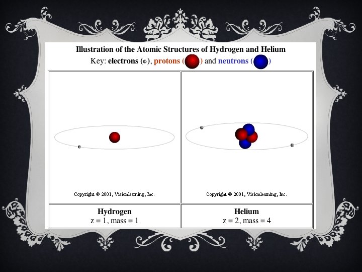
ELECTRONS v The smallest amount of electrical charge having the quality called negative polarity. v Electrons orbit the center of atoms. PROTONS v The proton is a basic particle with positive polarity. v Protons are located in the nucleus of atoms along with neutrons, particles which have neutral polarity.

ELECTRICALLY, ALL MATERIALS FALL INTO 1 OF 3 CLASSIFICATIONS: v Conductors v Insulators v Semi-Conductors

CONDUCTORS v Have 1 valence electron v Materials in which electrons can move freely from atom to atom are called conductors. v In general all metals are good conductors. v The purpose of conductors is to allow electrical current to flow with minimum resistance.

INSULATORS v Have 8 valence electrons v Materials in which electrons tend to stay put and do not flow easily from atom to atom are termed insulators. v Insulators are used to prevent the flow of electricity. v Insulating materials such as glass, rubber, or plastic are also called dielectrics, meaning they can store charges. v Dielectric materials are used in components like capacitors which must store electric charges.

SEMI-CONDUCTORS v. Have 4 valence electrons v. Materials which are neither conductors nor insulators v. Common semi conductor materials are carbon, germanium and silicone. v. Used in components like transistors

THE SYMBOL FOR CHARGE v The symbol for charge is Q which stands for quantity. v The practical unit of charge is called the coulomb (C). v One coulomb is equal to the amount of charge of 6. 25 X 1018 electrons or protons stored in a dielectric.

VOLTAGE v Potential refers to the possibility of doing work. v Any charge has the potential to do the work of attracting a similar charge or repulsing an opposite charge. v The symbol for potential difference is E (for electromotive force) v The practical unit of potential difference is the volt (V) v 1 volt is a measure of the amount of work required to move 1 C of charge

CURRENT v When a charge is forced to move because of a potential difference (voltage) current is produced. v In conductors - free electrons can be forced to move with relative ease, since they require little work to be moved. v So current is charge in motion. v The more electrons in motion the greater the current.

AMPERES v Current indicates the intensity of the electricity in motion. The symbol for current is I (for intensity) and is measured in amperes. v The definition of current is: I = Q/T v Where I is current in amperes, Q is charge in coulombs, and T is time in seconds.

1 AMPERE = 1 COULOMB PER SECOND

RESISTANCE v Opposition to the flow of current is termed resistance. v The fact that a wire can become hot from the flow of current is evidence of resistance. v Conductors have very little resistance. v Insulators have large amounts of resistance.

OHMS v The practical unit of resistance is the ohm designated by the Greek letter omega: Ω v A resistor is an electronic component designed specifically to provide resistance.

CLOSED CIRCUITS v In applications requiring the use of current, electrical components are arranged in the form of a circuit. v A circuit is defined as a path for current flow.

COMMON ELECTRONIC COMPONENT SYMBOLS

A COMPLEX AUDIO CIRCUIT

OPEN CIRCUITS

THE CIRCUIT IS A LOAD ON THE VOLTAGE SOURCE v The circuit is where the energy of the source (battery) is carried by means of the current through the various components. v The battery is the source, since it provides the potential energy to be used. v The circuit components are the load resistance - they determines how much current the source will produce.

DIRECTION OF ELECTRON FLOW v The direction of electron flow in our circuit is from the negative side of the battery, through the load resistance, back to the positive side of the battery. v Inside the battery, electrons move to the negative terminal due to chemical action, maintaining the potential across the leads.

ELECTRON FLOW IN A SIMPLE CIRCUIT

DC v Circuits that are powered by battery sources are termed direct current circuits. v This is because the battery maintains the same polarity of output voltage. The plus and minus sides remain constant.

WAVEFORM OF DC VOLTAGE

CHARACTERISTICS OF DC v It is the flow of charges in just one direction and. . . v The fixed polarity of the applied voltage which are characteristics of DC circuits

AC v An alternating voltage source periodically alternates or reverses in polarity. v The resulting current, therefore, periodically reverses in direction. v The power outlet in your home is 60 cycle ac meaning the voltage polarity and current direction go through 60 cycles of reversal per second. v All audio signals are AC also.

WAVEFORM OF AC VOLTAGE

COMPLEX VOLTAGE This is a more realistic view of what an audio signal’s voltage would look like

COMPARISON OF DC & AC DC Voltage AC Voltage Fixed polarity Reverses polarity Can be steady or vary in magnitude Varies in magnitude between reversals in polarity Steady value cannot be stepped up or down by a transformer Used for electrical power distribution Electrode voltage for I/O signal for tube and transistor amps Easier to measure Easier to amplify Heating Effects the same for both AC and DC current

MANY CIRCUITS INCLUDE BOTH AC & DC VOLTAGES v DC circuits are usually simpler than AC circuits. v However, the principles of DC circuits also apply to AC circuits.

IMPEDANCE v Impedance is resistance to current flow in AC circuits and its symbol is . v Impedance is also measured in ohms.

GROUNDING v In the wiring of practical circuits one side of the voltage source is usually grounded for safety. v For 120 V - ac power lines in homes this means one side of the voltage source is connected to a metal cold water pipe. v For electronic equipment, the ground just indicates a metal chassis, which is used as a common return for connections to the source.

COMMON SYMBOLS/ NAMES FOR GROUND IN ELECTRIC CIRCUITS

OHM’S LAW v The amount of current in a circuit is dependent on its resistance and the applied voltage. Specifically I = E/R v If you know any two of the factors E, I, and R you can calculate third. v Current I = E/R v Voltage E = IR v Resistance R = E/I

CURRENT IS DIRECTLY PROPORTIONAL TO VOLTAGE FOR A CONSTANT RESISTANCE

CURRENT IS INVERSELY PROPORTIONAL TO RESISTANCE FOR A CONSTANT VOLTAGE

POWER v The unit of electrical power is the watt. v Power is how much work is done over time. v One watt of power is equal to the work done in one second by one volt moving one coulomb of charge. Since one coulomb a second is an ampere: v Power in watts = volts x amperes v P=Ex. I

3 POWER FORMULAS v. P = E x I v. P = I 2 x R v. P = E 2 / R

CONVERSION FACTORS Prefix Symbol Relation to basic unit Examples Mega M 1, 000 or 1 x 10⁶ 5 MΩ = 5 x 10⁶ Ω Kilo k 1, 000 or 1 x 10³ 18 k. V = 18 x 103 V Milli m . 001 or 1 x 10 -3 48 m. A = 48 x 10 -3 A Micro . 000001 or 1 x 10 -6 15 V = 15 x 10 -6 V
- Slides: 40