Basic Concepts Applications of An Image Digital Images

Basic Concepts & Applications of An Image.

Digital Images Digital picture produced in 1921 from a coded tape by a telegraph printer with special type faces.

Digital Images Digital picture made in 1922 from a tape punched after the signals had crossed the Atlantic twice.

Digital Images Unretouched cable picture of Generals Pershing and Foch, transmitted in 1929 from London to New York by 15 -tone equipment.

Digital Images The first picture of the moon by a U. S. spacecraft. Ranger took this image on July 31, 1964 at 9: 09 A. M. EDT about 17 minutes before impacting the lunar surface.

Image Sources o Images can be categorized according to their source (e. g. , visual, X-ray, and so on). Principal energy source for images Ø Electromagnetic energy spectrum. Ø acoustic, ultrasonic, Ø Electronic (in the form of electron beams used in electron microscopy). Ø Synthetic images, used for modeling and visualization, are generated by computer

Electron Microscopy o The electron microscope is a type of microscope that uses a beam of electrons to create an image of the specimen. It is capable of much higher magnifications and has a greater resolving power than a light microscope, allowing it to see much smaller objects in finer detail.

Fundamental Steps in Digital Image Processing Ø Image Acquisition Image acquisition is the first process. Acquisition could be as simple as being given an image that is already in digital form. Generally, the image acquisition stage involves preprocessing, such as scaling. • • A digital image is produced by one or several image sensors. • • • These sensors may include: Light-sensitive cameras Range sensors Tomography devices Radar and ultra-sonic cameras, etc.

Fundamental Steps in Digital Image Processing Ø Depending on the type of sensor, the resulting image data is an ordinary 2 D image, a 3 D volume, or an image sequence. Ø The pixel values typically correspond to light intensity in one or several spectral bands

Steps involved:

Fundamental Steps in Digital Image Processing Ø Image enhancement is among the simplest and most appealing areas of digital image processing. Basically, the idea behind enhancement techniques is to bring out detail that is obscured, or simply to highlight certain features of interest in an image. A familiar example of enhancement is when we increase the contrast of an image because "it looks better. "

Fundamental Steps in Digital Image Processing Ø Image restoration is an area that also deals with improving the appearance of an image. However, unlike enhancement, which is subjective, image restoration is objective, in the sense that restoration techniques tend to be based on mathematical or probabilistic models of image degradation. Enhancement, on the other hand, is based on human subjective preferences regarding what constitutes a "good" enhancement result.

Fundamental Steps in Digital Image Processing Ø Color image processing is an area that has been gaining in importance because of the significant increase in the use of digital images over the Internet. Ø Wavelets are the foundation for representing images in various degrees of resolution.

Fundamental Steps in Digital Image Processing Ø Compression, as the name implies, deals with techniques for reducing the storage required to save an image, or the bandwidth required to transmit it. Although storage technology has improved significantly over the past decade, the same cannot be said for transmission capacity. This is true particularly in uses of the Internet, which are characterized by significant pictorial content.

Fundamental Steps in Digital Image Processing Ø Morphological processing deals with tools for extracting image components that are useful in the representation and description of shape. ØSegmentation procedures partition an image into its constituent parts or objects. In general, autonomous segmentation is one of the most difficult tasks in digital image processing.
 Representation and description")
Fundamental Steps in Digital Image Processing Representation and description (Feature Extraction) Representation and description almost always follow the output of a segmentation stage, which usually is raw pixel data, constituting either the boundary of a region (i. e. , the set of pixels separating one image region from another) or all the points in the region itself. In either case, converting the data to a form suitable for computer processing is necessary. The first decision that must be made is whether the data should be represented as a boundary or as a complete region. Boundary representation is appropriate when the focus is on external shape characteristics, such as corners and inflections. Regional representation is appropriate when the focus is on internal properties, such as texture or skeletal shape. In some applications, these representations complement each other. Choosing a representation is only part of the solution for transforming raw data into a form suitable for subsequent computer processing. A method must also be specified for describing the data so that features of interest are highlighted. Description, also called feature selection, deals with extracting attributes that result in some quantitative information of interest or are basic for differentiating one class of objects from another.

Summary of Previous Slide Feature extraction: • Image features at various levels of complexity are extracted from the image data. • Typical examples of such features are • Lines, edges and ridges. • Localized interest points such as corners, blobs or points. • More complex features may be related to texture, shape or motion.

Fundamental Steps in Digital Image Processing Ø Recognition is the process that assigns a label (e. g. , "vehicle") to an object based on its descriptors.

Componets of general purpose image processing system

Componets of general purpose image processing system With reference to sensing, two elements are required to acquire digital images. The first is a physical device that is sensitive to the energy radiated by the object we wish to image. The second, called a digitizer, is a device for converting the output of the physical sensing device into digital form. For instance, in a digital video camera, the sensors produce an electrical output proportional to light intensity. The digitizer converts these outputs to digital data.

Componets of general purpose image processing system Specialized image processing hardware usually consists of the digitizer just mentioned, plus hardware that performs other primitive operations, such as an arithmetic logic unit (ALU), which performs arithmetic and logical operations in parallel on entire images. One example of how an ALU is used is in averaging images as quickly as they are digitized, for the purpose of noise reduction. This type of hardware sometimes is called a front-end subsystem. Software for image processing consists of specialized modules that perform specific tasks. A well-designed package also includes the capability for the user to write code that, as a minimum, utilizes the specialized modules. More sophisticated software packages allow the integration of those modules and general-purpose software commands from at least one computer language.

Componets of general purpose image processing system Mass storage capability is a must in image processing applications. An image of size 1024 X 1024 pixels, in which the intensity of each pixel is an 8 -bit quantity, requires one megabyte of storage space if the image is not compressed. When dealing with thousands, or even millions, of images, providing adequate storage in an image processing system can be a challenge. Digital storage for image processing applications falls into three principal categories: A) short term storage for use during processing, B) on-line storage for relatively fast recall, and C) archival storage, characterized by infrequent access. Image displays in use today are mainly color (preferably flat screen) TV monitors. Monitors are driven by the outputs of image and graphics display cards that are an integral part of the computer system.

Componets of general purpose image processing system Hardcopy devices for recording images include laser printers, film cameras, heat-sensitive devices, inkjet units, and digital units, such as optical and CD-ROM disks. Networking is almost a default function in any computer system in use today. Because of the large amount of data inherent in image processing applications, the key consideration in image transmission is bandwidth. In dedicated networks, this typically is not a problem, but communications with remote sites via the Internet are not always as efficient. Fortunately, this situation is improving quickly as a result of optical fiber and other broadband technologies.

Simple Image Model Ø Ø Ø Images are denoted by two-dimensional functions of the form f(x, y). The value or amplitude of / at spatial coordinates (x, y) is a positive scalar quantity. f(x, y) must be nonzero and finite; that is, 0 < f(x, y) < The function f(x, y) may be characterized by two components: 1. The amount of source illumination incident on the scene being viewed, 2. The amount of illumination reflected by the objects in the scene. Appropriately, these are called the illumination and reflectance components and are denoted by i(x, y) and r(x, y), respectively.

What is an Image? Ø The two functions combine as a product to form f(x, y): Ø f(x, y) = i(x, y)r(x, y) 0 < i(x, y) < and where 0 < r(x, y) < 1. The following average numerical figures illustrate some typical ranges of i(x, y) for visible light. Ø On a clear day, the sun may produce in excess of 90, 000 lm/m 2 of illumination on the surface of the Earth. Ø On a cloudy day it decreases to less than 10, 000 lm/m 2. ØOn a clear evening, a full moon yields about 0. 1 lm/m 2 of illumination. ØThe typical illumination level in a commercial office is about 1000 lm/m 2.
 Values Typical values of reflection r(x, y) are: Ø 0. 01")
Reflection r(x, y) Values Typical values of reflection r(x, y) are: Ø 0. 01 for black velvet Ø 0. 65 for stainless steel Ø 0. 80 for flat-white wall paint Ø 0. 90 for silver-plated metal Ø 0. 93 for snow.

What is an Image? Ø Illumination is the amount of light falling on the object, and , this is property of light source. Ø Reflectance is the light reflected back from object and this remains between 0 & 1. Ø Ø Reflectance=0 (Transparent objects) Reflectance=1 (Opaque objects)
 that has been")
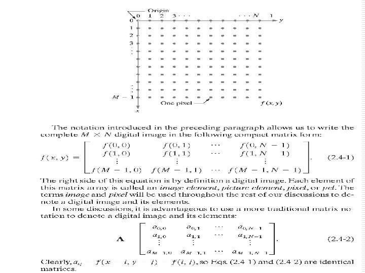
Digital Image: Ø A digital image is an image f(x, y) that has been “discritized” both in spatial & in brightness. Ø A 2 D matrix whose rows & columns identify a unique point in the image. Ø The corresponding matrix element value identifies the graylevel at that point. Ø The elements of such a digital array are called image elements , picture elements , pixels or pel. Ø The size of the digital image varies with the application.

Digital Image:

Digitization: o A process of converting Analog Images in to Digital. o Consist of two steps. n Sampling o Digitization of spatial coordinates. n Quantization o Digitization of Amplitude Values.

Digitization: Analog Image Digital Image Quantization Sampling

Image Representation: o So, a Binary Image stored in computer can be shown as: 0 1 0 1 0 1 0 1 0 1 Memory Representation for a Digital Image Displayed
 is referred to as Image")
Sampling: § Digitization of spatial coordinates (x, y ) is referred to as Image Sampling. § How much samples are required to extract the enough information from Analog Image? § Decision is made by using famous “Sampling” Theorem. § Digitization process requires that a decision be made on the number of discrete grey levels allowed for each pixel. § The result of sampling and quantization is a matrix of real numbers.
 is approximated by")
Digital Image Approximation: o Suppose that a continuous Image f(x, y) is approximated by equally spaced samples to form a N*N array, such that: o f(x, y)= f(0, 0) f(1, 0) f(2, 0). . . f(N-1, 0) f(0, 1) f(1, 1) f(2, 1). . . f(N-1, 1) f(0, 2) f(1, 2) f(2, 2). . . f(N-1, 2) f(0, N-1) f(1, N-1) f(2, N-1). . . f(N-1, N-1)

Quantization: § Amplitude Digitization is called Gray-level Quantization. § § In Digital Image Processing let these quantities be integer powers of two; that is, N = 2 n and G = 2 m § Where G denotes number of Gray level and Discrete levels are equally spaced between 0 -L

Spatial & Gray Level Resolution: o It may be defined as the degree of discrete details of an image which is strongly dependent on both n and m. o The more these parameters are increased, the closer the digitized array will approximate the original image. o By reducing the number of samples an image is distorted (less information is available). o By decreasing the number of gray levels we get imperceptible image and is called False Contouring.

Spatial & Gray Level Resolution The quality of an image strongly depends upon the number of samples and gray levels; the more are these two, the better would be the quality of an image. But, this will result in a large amount of storage space as well because the storage space for an image is the product of dimensions of an image and the number of bits required to store gray levels. At lower resolution, an image can result in checkerboard effect or graininess. When an image of size 1024 * 1024 is reduced to 512 * 512, it may not show much deterioration, but when reduced to 256 * 256 and then rescaled back to 1024 * 1024 by duplication, it might show discernible graininess.
 Muet Central Library")
Original Image (MUET central Library) Muet Central Library

500*450 450*500 Muet Central Library

300*200 150*100 Muet Central Library

100*50 20*30 Muet Central Library
")
Gray- Level: o Intensity of monochrome image f at coordinates ( x, y ) is called gray level (L) of the image at that point of the image. § Where L lies in the range: L min <= L max.

Gray-Level of Digital Image: 64 gray-level Image 32 gray-level Image Muet Central Library

Gray-Level of Digital Image: 16 gray-level Image 8 gray-level Image Muet Central Library

Gray-Level of Digital Image: 4 gray-level Image 2 gray-level Image Muet Central Library

Gray Scale: o The Intensity value of any Pixel is called as Gray Level Value, and it is denoted by ‘ L ’. o The value of ‘L’ lies in a certain range, and this is called as Gray Scale. o [Lmin , Lmax] is the Gray Scale, such that Lmin <L< Lmax. o For Binary Images, the Gray scale used is [0, 1]. o For color Images, the Gray scale is [0, 255]
. o")
Gray Scale: o The interval between the L to 1 (for Binary Images). o We generally have the following conventions: [0, 7 ] 8 -levels [0, 15 ] 16 -levels [0, 31 ] 32 -levels [0, 255] 256 -levels n n n min and L max is usually taken from 0 The Low value represents BLACK. The high value represent WHITE. Intermediate Values give different shades.
1024*1024 image (b) 512*512 image resampled into 1024*1024")
Spatial and Gray-Level Resolution a b (a)1024*1024 image (b) 512*512 image resampled into 1024*1024 pixels MUET Central Library 49
256*256 image resampled into 1024*1024 pixels (d) 128*128")
Spatial and Gray-Level Resolution c d (c)256*256 image resampled into 1024*1024 pixels (d) 128*128 image resampled into 1024*1024 pixels MUET Central Library 50
 64*64 image resampled into 1024*1024 pixels (f)")
Spatial and Gray-Level Resolution e f (e) 64*64 image resampled into 1024*1024 pixels (f) 32*32 image resampled into 1024*1024 pixels MUET Central Library 51

Storage Requirements: o The storage capacity for a digital Image depends upon: o The Detail Available in Image. o The Gray Scale being used. o The detail available is represented in terms of the Resolution (rows * Cols) o The gray scale is represented in terms of encoded bits.

Storage Requirements: o The formula used for calculating “bits” required, is given by: B=M*N*k Where M= N= K= Number of Rows Number of Columns Bits required to encode the used Gray scale. o For encoding a gray scale of [0, 7] , that is 8 different gray values, we need 3 bits. o In case of Square Images (M=N), this becomes: B=N 2*k

Storage Requirements: n Example: o Find bits required to store a 4*4 digital Image , when we are using 64 different gray levels? n Solution: n n Resolution=4*4 Gray scale=[0, 63] Encoded bits =6 (coz 26 =64) So bits required are: n n n B=M*N*k B=4*4*6 =96 bits Answer

Storage Requirements: N/k 1 2 3 4 5 6 7 8 32 1024 2048 3072 4096 5120 6144 7168 8192 64 4096 8192 12288 16384 20480 24576 28672 32768 128 16384 32768 49152 65536 81920 98304 11468 8 13107 2 256 65536 13107 2 19660 8 26214 4 32768 0 39321 6 45875 2 52428 8 512 262144 52428 8 78643 2 10485 76 13107 20 15728 64 18350 08 20971 52 Table showing Bits required for some typical values of N (N 2 k)
 The electromagnetic")
Fields That Use Digital Image Processing Energy of one photon (electron volts) The electromagnetic spectrum arranged according to energy per photon Planck's constant, or h i-e

Fields That Use Digital Image Processing

Fields That Use Digital Image Processing

Achromatic & Chromatic Light that is void of color is called achromatic or monochromatic light. The only attribute of such light is its intensity, or amount. The term gray level generally is used to describe monochromatic intensity because it ranges from black, to grays, and finally to white. Chromatic Light Chromatic light spans the electromagnetic energy spectrum from approximately 0. 43 to.

Achromatic & Chromatic Light Three basic quantities are used to describe the quality of a chromatic light source: 1. Radiance; 2. luminance; 3. brightness. Radiance is the total amount of energy that flows from the light source, and it is usually measured in watts (W). Luminance, measured in lumens (lm), gives a measure of the amount of energy an observer perceives from a light source.

Achromatic & Chromatic Light For example, light emitted from a source operating in the far infrared region of the spectrum could have significant energy (radiance), but an observer would hardly perceive it; its luminance would be almost zero. Brightness is a subjective descriptor of light perception that is practically impossible to measure. It embodies the achromatic notion of intensity and is one of the key factors in describing color sensation.
 spectrum is just a name that scientists give")
Electromagnetic Spectrum o The electromagnetic (EM) spectrum is just a name that scientists give a bunch of types of radiation when they want to talk about them as a group. Radiation is energy that travels and spreads out as it goes-- visible light that comes from a lamp in your house and radio waves that come from a radio station are two types of electromagnetic radiation.

o Other examples of EM radiation are microwaves, infrared and ultraviolet light, X-rays and gamma-rays. Hotter, more energetic objects and events create higher energy radiation than cool objects. Only extremely hot objects or particles moving at very high velocities can create high-energy radiation like X-rays and gamma-rays. Here are the different types of radiation in the EM spectrum, in order from lowest energy to highest:

Gamma Rays o The highest energy, shortest wavelength electromagnetic radiations. Usually, they are thought of as any photons having energies greater than about 100 ke. V o Radioactive materials (some natural and others made by man in things like nuclear power plants) can emit gammarays. Big particle accelerators that scientists use to help them understand what matter is made of. The biggest gamma-ray generator of all is the Universe! It makes gamma radiation in all kinds of ways.

Gamma-Ray Imaging o Major uses of imaging based on gamma rays include nuclear medicine and astronomical observations. o In nuclear medicine, the approach is to inject a patient with a radioactive isotope that emits gamma rays as it decays. o Images are produced from the emissions collected by gamma ray detectors.

Cancer Treatment
 Bone Scan (b) PET Image")
Examples of Gamma-ray Imaging a b c d (a) Bone Scan (b) PET Image (c ) Cygnus Loop (d) Gamma radiation (bright spot) from a reactor valve. PET (Positron Emission Tomography)
 Ø Fig (a) : Images of this sort are")
Description about Figures(Gamma Ray Imaging) Ø Fig (a) : Images of this sort are used to locate sites of bone pathology, such as infections or tumors. Ø Fig (b): shows a tumor in the brain and one in the lung, easily visible as small white masses. Ø Fig (c): shows the Cygnus Loop imaged in the gamma-ray band. Ø Fig (d): shows an image of gamma radiation from a valve in a nuclear reactor. An area of strong radiation is seen in the lower, left side of the image. A star in the constellation of Cygnus exploded about 15, 000 years ago, generating a superheated stationary gas cloud (known as the Cygnus Loop) that glows in a spectacular array of colors.

X-rays Ø Electromagnetic radiation of very short wavelength and very high-energy; X-rays have shorter wavelengths than ultraviolet light but longer wavelengths than gamma rays. Ø Your doctor uses them to look at your bones and your dentist to look at your teeth. Hot gases in the Universe also emit X-rays.

X-ray Imaging Ø X-rays are among the oldest sources of EM radiation used for imaging. Ø The best known use of X-rays is medical diagnostics, but they are also used extensively in industry and other areas, like astronomy. Ø Angiography is another major application in an area called contrast- enhancement radiography. Ø This procedure is used to obtain images (called angiograms) of blood vessels.
 Ø Perhaps the best known of all uses of X-rays in")
X-ray Imaging (contd) Ø Perhaps the best known of all uses of X-rays in medical imaging is computerized axial tomography(CAT). Ø Due to their resolution and 3 -D capabilities, CAT scans revolutionized medicine from the moment they first became available in the early 1970 s. Ø X-rays, are used to examine circuit boards for flaws in manufacturing, such as missing components or broken traces.
 Chest X-ray (e) Cygnus")
Examples of X-ray Imaging a d b e c (a) Chest X-ray (e) Cygnus Loop (b) Aortic Angiogram (c ) Head CT (d) Circuit Boards
 Ø Figure (a) shows a familiar chest X-ray generated")
Description about Figures(X Ray Imaging) Ø Figure (a) shows a familiar chest X-ray generated simply by placing the patient between an X-ray source and a film sensitive to X-ray energy. Ø Figure (b): shows an example of an aortic angiogram. Ø Figure (c) shows a typical head CAT slice image. Ø Figure (d) shows an X-ray image of an electronic circuit board. Such images, are used to examine circuit boards for flaws in manufacturing, such as missing components or broken traces. Ø Figure (e) shows an example of X-ray imaging in astronomy. This image is the Cygnus Loop.

Ultra. Violet Light o Electromagnetic radiation at wavelengths shorter than the violet end of visible light , Sun is a source of ultraviolet (or UV) radiation, because it is the UV rays that cause our skin to burn! Stars and other "hot" objects in space emit UV radiation. The atmosphere of earth effectively blocks the transmission of most ultraviolet light.

Imaging in the Ultraviolet Band Ø Applications of ultraviolet "light” include lithography, industrial inspection, microscopy, lasers, biological imaging, and astronomical observations. Lithography : A method of planographic printing from a metal or stone surface
 Normal corn (b) Smut Corn (c")
Examples of Ultraviolet Band b a c (a) Normal corn (b) Smut Corn (c ) Cygnus Loop Smut : A disease of cereals, corn grasses and onions.
 Ø Figure (a) shows a fluorescence microscope image of normal")
Description about Figures(Ultraviolet Band) Ø Figure (a) shows a fluorescence microscope image of normal corn. Ø Figure(b) shows corn infected by "smut, " a disease of cereals, corn, grasses, onions, and sorghum. Ø Figure (c) shows the Cygnus Loop imaged in the highenergy region of the ultraviolet band.

Infrared o Electromagnetic radiation at wavelengths longer than the red end of visible light and shorter than the microwaves (roughly between 1 and 100 microns). Almost none of the infrared portion of electromagnetic spectrum can reach the surface of earth. ØWe often think of this as being the same thing as 'heat', because it makes our skin feel warm.

Imaging in the Visible and Infrared Bands Ø Applications include light microscopy, astronomy, remote sensing, industry, and law enforcement.
 Taxol(anticancer agent)")
Examples of Visible and Infrared Bands a b c e d (a) Taxol(anticancer agent) (b) Cholestrol (c ) Microprocessor (d) Nickle oxidethin film (e) Surface of Audio CD f (f) Organic superconductor

Table 1. 1: Thematic Bands in NASA’s LANDSAT Satellite LANDSAT satellite obtains and transmits images of Earth from space for monitoring environmental conditions of the planet.

LANDSAT satellite images of Washington D. C area. The numbers refer to thematic bands in Table 1. 1.

Multispectral image of Hurricane Image taken by satellite using sensors in the visible and infrared bands.

Infrared satellite images of Americas. These images are part of Nighttime Lights of the world data set, which provide global inventory of human settlements.

Infrared satellite images of remaining populated part of the world.

Visual spectrum in automated visual inspection of manufactured goods. b a c d e e d (a) Circuit board controller (b) Packaged pills (c) Bottles (d) Bubbles in clear-plastic product. (e) Cereal (f) Intraocular implant. f
: A typical image processing task with products like")
Description about Figures Ø Figure (a): A typical image processing task with products like this is to inspect them for missing parts (the black square on the top, right quadrant of the image is an example of a missing component). Ø Figure (b): is an imaged pill container. The objective here is to have a machine look for missing pills. Ø Figure (c) shows an application in which image processing is used to look for bottles that are not filled up to an acceptable level.
 shows a clear-plastic part with an unacceptable number")
Description about Figures Ø Figure (d) shows a clear-plastic part with an unacceptable number of air pockets in it. Detecting anomalies like these is a major theme of industrial inspection. Ø Figure (e) shows a batch of cereal during inspection for color and the presence of anomalies such as burned flakes. Ø Figure(f) shows an image of an intraocular implant.

Imaging in the Microwave Band Ø Electromagnetic radiation which has a longer wavelength (between 1 mm and 30 cm) than visible light. Ø Microwaves can be used to study the Universe, communicate with satellites in Earth orbit, and cook popcorn.

Imaging in the Microwave Band Ø The dominant application of imaging in the microwave band is radar. The unique feature of imaging radar is its ability to collect data over virtually any region at any time, regardless of weather or ambient lighting conditions. Some radar waves can penetrate clouds, and under certain conditions can also see through vegetation, ice, and extremely dry sand. In many cases, radar is the only way to explore inaccessible regions of the Earth's surface. An imaging radar works like a flash camera in that it provides its own illumination (microwave pulses) to illuminate an area on the ground and take a snapshot image. Instead of a camera lens, a radar uses an antenna and digital computer processing to record its images. In a radar image, one can see only the microwave energy that was reflected back toward the radar antenna.

Examples of Microwave Band Spaceborne radar image of mountains in Southeast Tibet
 Thumb print (b) Paper")
Examples of Visual spectrum a b c d e (a) Thumb print (b) Paper currency (c ) and (d) Automated license plate reading.
 Ø Figure (a) shows a thumb print. Images of fingerprints")
Description about Figures(Visual Spectrum) Ø Figure (a) shows a thumb print. Images of fingerprints are routinely processed by computer, either to enhance them or to find features that aid in the automated search of a database for potential matches. Ø Figure (b) shows an image of paper currency. Applications of digital image processing in this area include automated counting and, in law enforcement, the reading of the serial Ø number for the purpose of tracking and identifying bills. Ø Figure(c) and Figure (d) are examples of automated license plate reading.

Radio Waves Ø Electromagnetic radiation which has the lowest frequency, the longest wavelength, and is produced by charged particles moving back and forth. Ø The atmosphere of the Earth is transparent to radio waves with wavelengths from a few millimeters to about twenty meters

Radio Waves o Yes, this is the same kind of energy that radio stations emit into the air for your boom box to capture and turn into your favorite tunes. But radio waves are also emitted by other things. . . such as stars and gases in space.

Imaging in the Radio Band Ø The major applications of imaging in the radio band are in medicine and astronomy. Ø In medicine radio waves are used in magnetic resonance imaging (MRI). Ø This technique places a patient in a powerful magnet and passes radio waves through his or her body in short pulses.
 a (a) Human knee b (b) Human spine")
Examples of Radio Band (MRI Images) a (a) Human knee b (b) Human spine MRI: Magnetic Resonance Imaging
 covering the electromagnetic spectrum.")
Image of the Crab Pulsar(in the center of images) covering the electromagnetic spectrum.

o

Examples in which Other Imaging Modalities Are Used Although imaging in the electromagnetic spectrum is dominant by far, there a number of other imaging modalities that also are important. Other imaging modalities are : 1. acoustic imaging, 2. electron microscopy, 3. and synthetic (computer-generated) imaging.

Imaging using "sound" finds application in Ø Geological exploration, Ø Industry, ØMedicine. Ø Geological applications use sound in the low end of the sound spectrum (hundreds of Hertz) Ø imaging in other areas use ultrasound (millions of Hertz).

o The most important commercial applications of image processing in geology are in mineral and oil exploration. For image acquisition over land, one of the main approaches is to use a large truck and a large flat steel plate. The plate is pressed on the ground by the truck, and the truck is vibrated through a frequency spectrum up to 100 Hz. The strength and speed of the returning sound waves are determined by the composition of the earth below the surface. These are analyzed by computer, and images are generated from the resulting analysis.
 trap. Seismic:")
Cross-sectional image of seismic model. The arrow points to a hydrocarbon(oil and/gas) trap. Seismic: Subject to or caused by an earthquake or earth vibration

Ultrasound Imaging Ø Although ultrasound imaging is used routinely in manufacturing. Ø The best known applications of this technique are in medicine, especially in obstetrics, where unborn babies are imaged to determine the health of their development. Obstetrics The branch of medicine dealing with childbirth and care of the mother

Ultrasound Images are generated using following procedure angled to obtain various images
 Baby (b) Another view of baby (c)")
Ultrasound Images a c b d (a) Baby (b) Another view of baby (c) Thyroids (d) Muscle layers showing lesion Lesion: Any visible abnormal structural change in a bodily part
 and (b) Fractal Images (c) and (d)")
Fractal Images a b d c (a) and (b) Fractal Images (c) and (d) Images generated from 3 -D computer model of the object shown Fractal images: are striking examples of computer generated images

o Refer These slide after slide no. 38

Resolution o The resolution can be defined in many ways. Such as pixel resolution , spatial resolution etc o You have probably seen that in your own computer settings , you have monitor resolution of 800 x 600 , 640 x 480 e. t. c o In pixel resolution , the term resolution refers to the total number of count of pixels in an digital image. o For example. If an image has M rows and N columns , then its resolution can be defined as M X N. o If we define resolution as the total number of pixels , then pixel resolution can be defined with set of two numbers. The first number the width of the picture , or the pixels across columns , and the second number is height of the picture. o We can say that the higher is the pixel resolution , the higher is the quality of the image. o We can define pixel resolution of an image as 4500 X 550

Megapixels o Defination: o This term refers to the size of an image, usually in reference to a photo from a digital camera or camera phone. Megapixel means one million pixels. The resolution of digital cameras and camera phones is often measured in megapixels. For example, a 5 -megapixel camera can produce images with five million total pixels. o o o o We can calculate mega pixels of a camera using pixel resolution. Column pixels (width ) X row pixels ( height ) / 1 Million. The size of an image can be defined by its pixel resolution. Size = pixel resolution X bpp ( bits per pixel ) Calculating the mega pixels of the camera Lets say we have an image of dimension: 2500 X 3192. Its pixel resolution = 2500 * 3192 = 7982350 bytes. Dividing it by 1 million = 7. 9 = 8 mega pixel (approximately).

Aspect ratio o Another important concept with the pixel resolution is aspect ratio. o Aspect ratio is the ratio between width of an image and the height of an image. It is commonly explained as two numbers separated by a colon (8: 9). This ratio differs in different images , and in different o screens. The common aspect ratios are: o 1. 33: 1, 1. 37: 1, 1. 43: 1, 1. 50: 1, 1. 56: 1, 1. 66: 1, 1. 75: 1, 1. 78: 1, 1. 85: 1, 2. 00: 1, e. t. c o ADVANTAGE: o Aspect ratio maintains a balance between the appearance of an image on the screen , means it maintains a ratio between horizontal and vertical pixels. It does not let the image to get distorted when o aspect ratio is increased

Aspect ratio o Finding the dimensions of the image from aspect ratio: o Aspect ratio tells us many things. With the aspect ratio, we can calculate the dimensions of the image along with the size of the image o For example o If you are given an image with aspect ratio of 6: 2 of an image of pixel resolution of 480000 pixels given the image is an gray scale image. o And you are asked to calculate two things. o 1. Resolve pixel resolution to calculate the dimensions of o image o 2 Calculate the size of the image

Aspect ratio SOLUTION: GIVEN: Aspect ratio: c: r = 6: 2 Pixel resolution: c * r = 480000 Bits per pixel: grayscale image = 8 bpp FIND: Number of rows = ? Number of cols = ? Storage size=?
")
o Eq: 1 c: r= 6: 2 o Eq: 2 c*r=480000 c=3 r (i) c=480000/r (ii) o Comparing (i) & (ii) i-e: o 3 r=480000/r r 2 =480000/3=160000 400 Putting it in (i) we get, o c= 3*400 =1200 o r= o So pixel resolution=c*r=1200*400

o 2 nd part storage size , o Storage size= Pixel resolution* Bits per pixel(bpp) o =1200*400*8= 3840000 bits o Size in bytes = 3840000/8= 480000 bytes o Size in kilobytes= 48 kb (approximately)
- Slides: 116