Baseband pulse and digital signaling Introduction 1 How


Baseband pulse and digital signaling • Introduction: 1. How to encode analog waveforms into baseband pulse signals (sampling) 2. How to approximate analog signals with digital signals (quantizing) 3. How to process the digital baseband signals so that their bandwidth is minimized Four main goals : 1. Principle of PCM 2. ( Spectrum of digital signals) 3. (The filtering effects on the digital pulses) 4. TDM--time-division-multiplexing

• A digital transmission system for analog signal: Analog source sampling M level encoding quant. PCM signal clock PCM signal Transmission filter HT(f) Channel filter HC(f) wc(t) Receiver filter HR(f) Analog output noise filter sampling decoder wout(t) LPF Quantized PAM

Pulse amplitude modulation • PAM: Pulse Amplitude Modulation • First step to digitalize an analog signal • PAM: conversion of a time-continuous analog waveform to a time-discrete analog waveform • In sampling theorem, we use the sampling values ws(t) (timediscrete) (sampling from w(t) using sampling impulse or delta function train) and (sinx/x) orthogonal function to reproduce the original function w(t) (time-continuous) without error. Here, we will use another form (looks like sampling impulse) of waveform to provide the information necessary to reconstruct w(t). • Because the pulses are used, we can expect the bandwidth of PAM waveform to be wider than w(t).
 baseband signal (BHz) ws(t) baseband pulses pulse sampling From sampling theorem,")
• w(t) baseband signal (BHz) ws(t) baseband pulses pulse sampling From sampling theorem, the sampling rate is fs≥ 2 B (Nyquist rate). The impulse sampling is: ws(t) w(t) t Two classes of PAM signals: Natural sampling (gating) Instantaneous sampling (flat-top)
 • Definition: If w(t) is an analog bandlimited waveform (BHz), the PAM")
Natural sampling(gating) • Definition: If w(t) is an analog bandlimited waveform (BHz), the PAM signal that uses natural sampling is ws(t)=w(t)s(t) where s(t)=∑∏[(t-k. Ts)/τ] and fs=1/Ts≥ 2 B • Theorem: The spectrum for a natural sampling PAM signal ws(t) is: Ws(f)=F[ws(t)]=d∑(sinπnd/πnd)W(f-nfs) where fs= Ts, d is the duty cycle of s(t) (d= τ/ Ts), and W(f) is the FT of w(t). Proof: Ws(f)=W(f)*S(f) and we have s(t)’s Fourier series: s(t)=∑cnej 2πnfs and cn=d (sinπnd/πnd)
![So: S(f)=F[s(t)]=∑cnδ(f-nfs) Ws(f)=W(f)*S(f)=d∑(sinπnd/πnd)W(f-nfs) w(t) s(t) t Baseband analog waveform ws(t) τ t Ts Switching](http://slidetodoc.com/presentation_image_h2/2c70a8348af6747431bcaaa24c3a66a5/image-7.jpg "So: S(f)=F[s(t)]=∑cnδ(f-nfs) Ws(f)=W(f)*S(f)=d∑(sinπnd/πnd)W(f-nfs) w(t) s(t) t Baseband analog waveform ws(t) τ t Ts Switching")
So: S(f)=F[s(t)]=∑cnδ(f-nfs) Ws(f)=W(f)*S(f)=d∑(sinπnd/πnd)W(f-nfs) w(t) s(t) t Baseband analog waveform ws(t) τ t Ts Switching waveform (d=1/3) t Resulting PAM signal

• Generation of natural sampling PAM signal and its spectrum: Analog bilateral switch w(t) ws(t) Generation of PAM Clock Ws(f) │W(f)│ d│sin(πτf)/πτf│ d=1/3 1 -B B f Magnitude spectrum of w(t) fs Magnitude spectrum of ws(t) f

• For this example with d=1/3, the spectrum is zero for f=± 3 fs, ± 6 fs, …So the choice of d will infect the resulting spectrum. • The null bandwidth is 12 B (3 fs). So PAM signal ‘s bandwidth is much larger than the bandwidth of the original analog waveform. • If fs≥ 2 B, no overlap of spectrum • According to Ws(f), we can use an ideal low-pass filter to recover the original waveform w(t). Ws(f) d│sin(πτf)/πτf│ LPF d=1/3 fs Recovering w(t) from ws(t) f
 PAM (Gating)")
• Demodulation of a natural sampling PAM signal Analog multiplier ws(t) PAM (Gating) Cw(t) LPF H(f) Local oscillator -fco f
 • Using flat-top signaling to convert an analog waveform to")
Instantaneous sampling (Flat-top PAM) • Using flat-top signaling to convert an analog waveform to pulse signaling impulse sampling’s generalization • Definition: if w(t) is an analog bandlimited waveform (BHz), the instantaneous sampled PAM signal is given by: ws(t)=∑w(k. Ts)h(t-k. Ts) where h(t) denotes the sampling-pulse shape, and for flat-top sampling the pulse shape is h(t)= Π(t/τ) τ≤Ts and f s≥ 2 B • Theorem: the spectrum for a flat-top PAM signal is Ws(f)=(1/Ts)H(f) ∑W(f-kfs) where H(f)= τ sin(π τ f)/(π τ f)
![• Proof: we have ws(t)=∑w(k. Ts)h(t-k. Ts) =h(t)*∑w(k. Ts)δ(t-k. Ts) =h(t)*[w(t)∑δ(t-k. Ts)] then](http://slidetodoc.com/presentation_image_h2/2c70a8348af6747431bcaaa24c3a66a5/image-12.jpg "• Proof: we have ws(t)=∑w(k. Ts)h(t-k. Ts) =h(t)*∑w(k. Ts)δ(t-k. Ts) =h(t)*[w(t)∑δ(t-k. Ts)] then")
• Proof: we have ws(t)=∑w(k. Ts)h(t-k. Ts) =h(t)*∑w(k. Ts)δ(t-k. Ts) =h(t)*[w(t)∑δ(t-k. Ts)] then the spectrum is: Ws(f)=H(f)[W(f)* ∑e-j 2πfk. Ts] Here we have (1/Ts)∑δ(f-kfs)= (1/Ts)∑cne-j 2πfn. Ts and cn is the Fourier series’ coefficient of the impulse train: cn=1/fs and Ws(f)=H(f)[W(f)* (1/Ts)∑δ(f-kfs)] =H(f)[(1/Ts)∑W(f)*δ(fkfs)] =(1/Ts)H(f)∑W(f-kfs)
│ Ws(f) τ /Ts│sin(πτf)/πτf│ 1 -B B f fs Magnitude")
• Spectrum diagram: │W(f)│ Ws(f) τ /Ts│sin(πτf)/πτf│ 1 -B B f fs Magnitude spectrum of w(t) Magnitude spectrum of ws(t) f • Demodulation of flat-top PAM waveform: Analog multiplier ws(t) PAM (flat-top) Cw(t) LPF H(f) Local oscillator -fco f

Pulse Code Modulation--PCM • Definition: PCM is essentially analog-to-digital conversion of a special type where the information contained in the instantaneous samples of an analog bandlimited signal is represented (encoded) by digital words in a serial bit stream. • If a digital words has n binary digits, we can have M=2 n possible unique code words, each code word corresponding to a certain amplitude level. • Question: the sample from analog signal can be any one of an infinite number of levels, how can we represent the possible infinite number of levels by only M levels? • Answer: approximation--quantification

• The analog sample value will be replaced by one of the closest allowed M values. And each allowed value corresponds one of M allowed n bits digital word. • PCM’s advantages: • • • digital circuit IC cheep PCM can accommodate all type of analog sources easy to realize TDM long-distance communication noise performance of a digital system better than the analog • main disadvantage: • a much more wider bandwidth • EX. : for voice telephone: analog signal 300 -3400 Hz • PCM system: minimum bandwidth 34 k. Hz

Sampling, Quantizing and Encoding • PCM signal generated from analog signal: three main steps Analog source sampling M level encoding quant. PCM signal clock PCM transmitter Analog output filter sampling decoder LPF Quantized PAM PCM receiver

• Quantizer: M level Input: flat-top PAM signal Output: M level digital signal quant. Output voltage M=8 levels Input voltage M=8, n=3 (3 bits digital words)
 {w(n. Ts)} Sampling • Quantizing error")
• Sampler and encoder: Quantizing levels w(t) {w(n. Ts)} Sampling • Quantizing error quantizing noise (irreversible) see page 139 figure 3 -8 c • PCM signal output serial binary code • Three-bit Gray code for M=8(page 140 table 3 -1) Mirror image a better anti-noise performance

• Bandwidth of PCM: • Question: what is the spectrum of a PCM signal? From PAM and encoding processes, we known that the bandwidth of a PCM signal will depend on the bit rate and the pulse shape. Bit rate sampling rate (≥ 2 B) analog waveform’s bandwidth Bit rate quality of PCM signal Pulse shape PCM signal’s PSD Calculation: bit rate R=nfs (M=2 n) we will learn that the minimum bandwidth for a PCM waveform will be: BPCM≥ 1/2 R

• Effects of noise The analog signal, recovered from PCM signal, is corrupted by two kinds of noises: 1. Bit error produced by channel’s gaussian white noise and improper channel filtering (ISI) 2. Quantizing noise One formula for average S/N calculation: (S/N)out=M 2/[1+4(M 2 -1)Pe] where M is number of quantized levels , Pe is the probability of bit error in the recovered binary PCM signal. • If the system have not bit error, so the noise is caused only by the quantification, then we have: (S/N)out=M 2


• The table 3 -2 gives us an ideal for different factors in a PCM system such as M, B, S/N. (see page 142) • To realize this SNS, one critical assumption the quantification is uniform over the peak-to-peak level of the analog waveform Vmax w(t) M level uniform quantification t Vmin

• From a practical viewpoint, four types of quantized noise: 1. Overload noise the peak value of analog waveform exceeds the quantizer’s peak value 2. Random noise random quantification’s error 3. Granular noise uniform quantification caused 4. Hunting noise oscillation of quantizer’s output due to relatively constant input M=2 n, (n the digital word’s length) so the average SNR in decibel is : (S/N)db=6. 02 n From this formula(6 d. B rule), every additional bit added to digital word will gain 6 d. B in performance of SNR.

• Ex. Design of a PCM system • analog source: voice 300 -3400 Hz • sampling: so minimum sampling frequency (Nyquist rate) : 2*3. 4 k. Hz=6. 8 k. Hz, in reality fs=8 k. Hz • quantizing and encoding: M=256, the digital word n=8 bits( 7 bits for quantification, 1 bit for parity) • bit rate R: 8000 samples/sec, 8 bits/sample so: R=8000*8 bits/sec=64 kbps if we use NRZ code for transmission, then the baud rate is D=64 k. Bauds • bandwidth: analog signal 3400 Hz, PCM signal : absolute bandwidth=∞ the first null bandwidth: (B)null=R=64 k. Hz
output=M 2=128*128=42 d. B •")
• the parity bit: error correction • performance: (S/N)output=M 2=128*128=42 d. B • for a performance of 90 d. B, the length of digital word will be 15 bits!!! The bandwidth will be 120 k. Hz • Question: for the most real waveforms, they have the amplitude value near zero. So with quantizing method that we have adopted, the quantizing noise for small signal becomes very important and the quality of recovered analog signal will be insupportable. How can we do? • Answer: non-uniform quantizing method.

Non-uniform quantizing: μ-law and A-law • For non uniform amplitude distribution’s signals, the granular quantizing noise will be a serious problem if the step size of quantizer is not reduced for amplitude value near zero. • The concept: Vmax w(t) Few levels More quantizing levels Vmin

• For realize this type of quantizing, we can adopt two approach ways: • first: direct way • second: using a non uniform circuit to amplify the small signal and compress the large one. x PAM input Non-linear quantizer Non linear amplifier y=f(x) Non-uniform quantized PAM output linear quantizer y=f(x) Non-uniform quantized PAM output

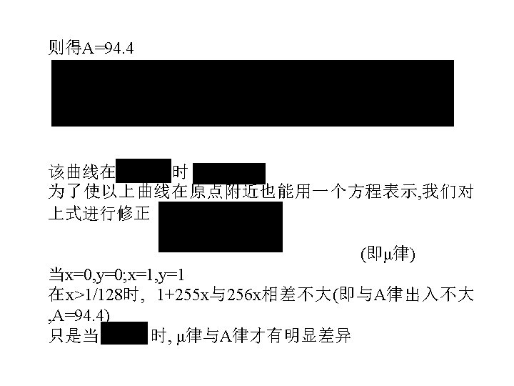
• In general, the second method is adopted. Let first that the analog signal passes through a compression (nonlinear)amplifier • Concept of non-uniform quantification • 1. The step of quantification is proportional to the input of quantizer. • 2. The RMS of quantizing noise power is proportional to the sampling value. • To satisfy these conditions, we have two widely used compression laws---- μ-law and A-law y=ln(1+μx)/ln(1+μ) (μ-law ) y=Ax/(1+ln. A) 0≤x≤ 1/A (A-law) y=(1+ln. Ax)/(1+ln. A) 1/A≤x≤ 1

where μ=255 and A=87. 6 y 1 y=x 0 1 x Normalized compression characteristics (compandor) • Why have the values of μ=255 and A=87. 6 be chosen? • For practical reasons, explications


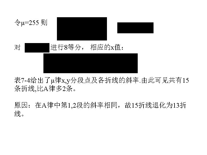

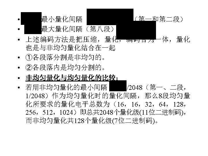
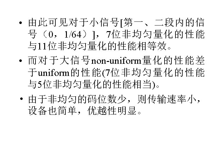
• The composition of non-uniform quantized code of the voice: • 1. Normalization and polarity (polarity bit 1 for x>0 and 0 for x<0) • 2. Segmentation for non-uniform quantification • 3. Non-uniform quantification for each segment (3 bits for 8 segments) • 4. Uniform quantification for inside of each segment (4 bits for 16 quantizing levels) Polarity bit Segment bits Linear quantizing bits for inside of each segment

- Slides: 58