
B R C G A S E Q
B R C G A S E Q U I P M E N T Plug&Drive & S 24. 11
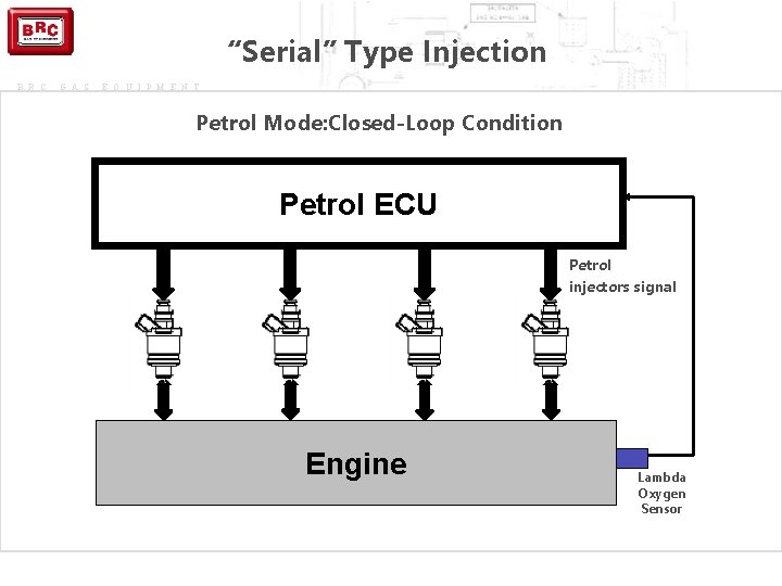
“Serial” Type Injection B R C G A S E Q U I P M E N T Petrol Mode: Closed-Loop Condition Petrol ECU Petrol injectors signal Engine Lambda Oxygen Sensor
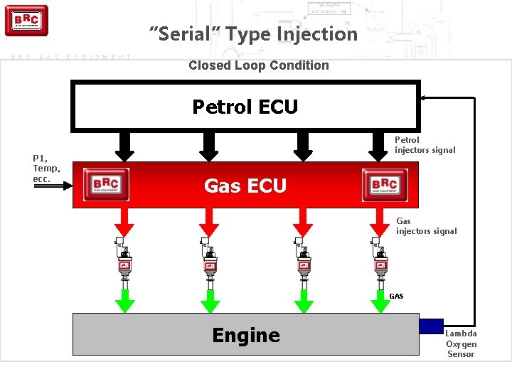
“Serial” Type Injection B R C G A S E Q U I P M E N T Closed Loop Condition Petrol ECU P 1, Temp, ecc. Petrol injectors signal Gas ECU Gas injectors signal GAS Engine Lambda Oxygen Sensor
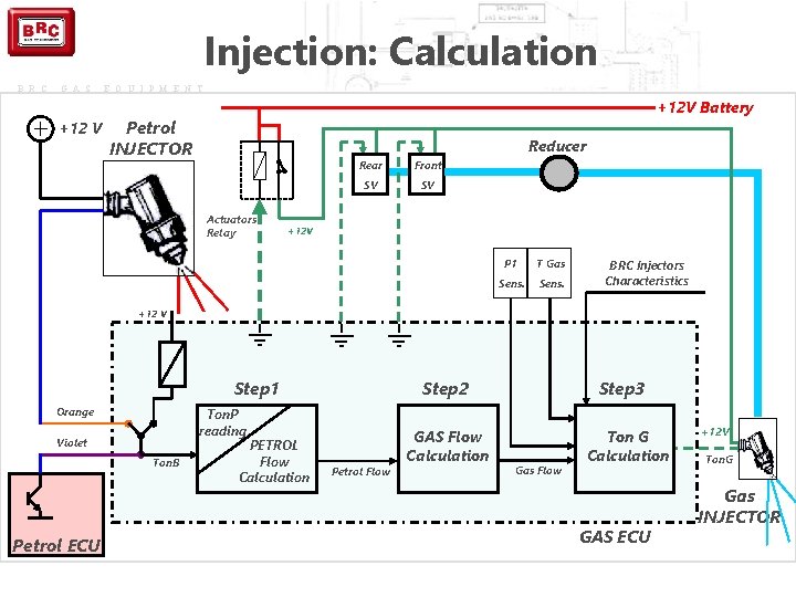
Injection: Calculation B R C G A S +12 V E Q U I P M E N T +12 V Battery Petrol INJECTOR Reducer Actuators Relay Rear Front SV SV +12 V P 1 T Gas Sens. BRC Injectors Characteristics +12 V Step 1 Orange Ton. P reading Violet Ton. B Petrol ECU PETROL Flow Calculation Step 3 Step 2 Petrol Flow GAS Flow Calculation Gas Flow Ton G Calculation GAS ECU +12 V Ton. G Gas INJECTOR
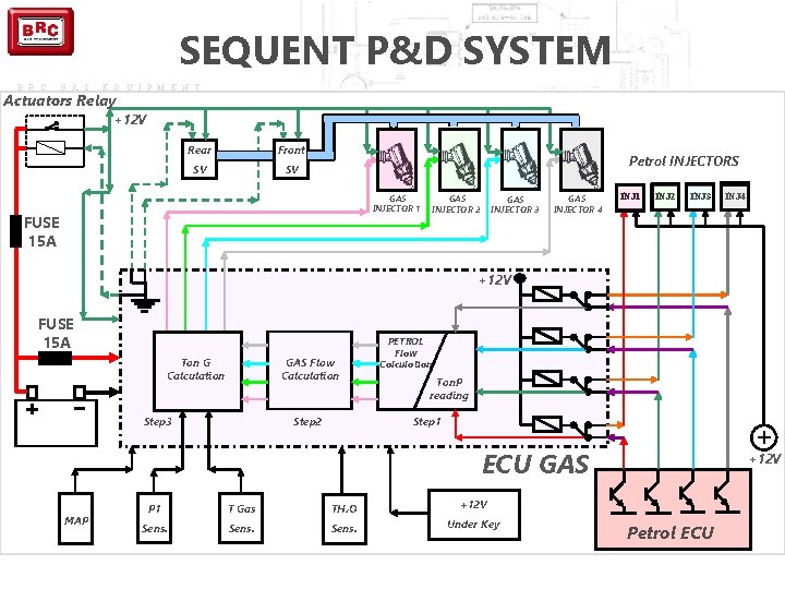
SEQUENT P&D SYSTEM B R C G A S E Q U I P M E N T Actuators Relay +12 V Rear Front SV SV Petrol INJECTORS GAS INJECTOR 1 FUSE 15 A GAS INJECTOR 2 GAS INJECTOR 3 GAS INJECTOR 4 INJ 1 INJ 2 INJ 3 INJ 4 +12 V FUSE 15 A GAS Flow Calculation Ton G Calculation Step 3 PETROL Flow Calculation Ton. P reading Step 1 Step 2 ECU GAS MAP P 1 T Gas TH 2 O +12 V Sens. Under Key +12 V Petrol ECU
B R C G A S E Q U I P M E N T In the new kit S 24. 11 The actuator Relay is internal to the Gas ECU
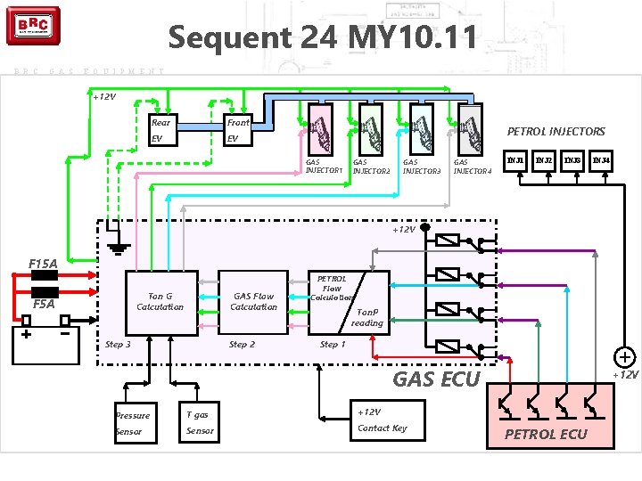
Sequent 24 MY 10. 11 B R C G A S E Q U I P M E N T +12 V Rear Front EV EV PETROL INJECTORS GAS INJECTOR 1 GAS INJECTOR 2 GAS INJECTOR 3 GAS INJECTOR 4 INJ 1 INJ 2 INJ 3 INJ 4 +12 V F 15 A GAS Flow Calculation Ton G Calculation F 5 A Step 3 Step 2 PETROL Flow Calculation Ton. P reading Step 1 GAS ECU Pressure T gas +12 V Sensor Contact Key +12 V PETROL ECU
B R C G A S E Q U I P M E N T The General Wiring Diagrams
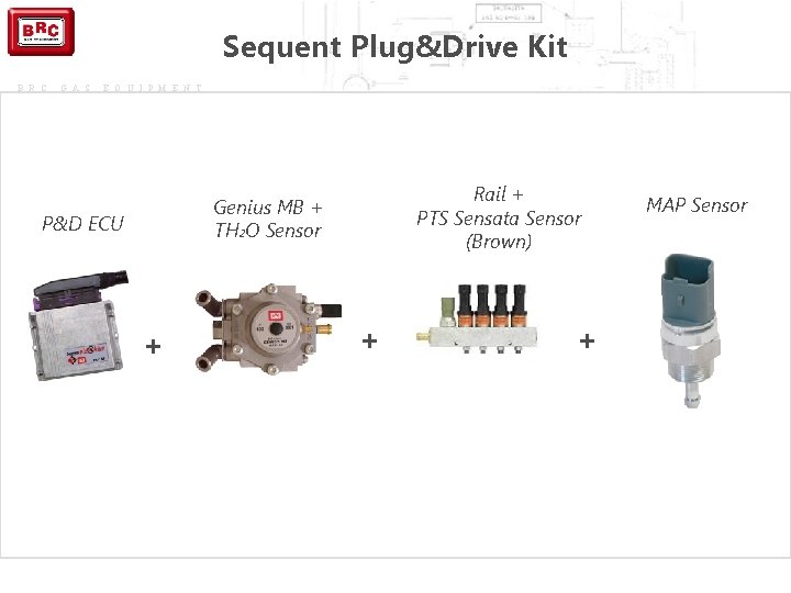
Sequent Plug&Drive Kit B R C G A S E Q U I P M E N T Rail + PTS Sensata Sensor (Brown) Genius MB + TH 2 O Sensor P&D ECU + + + MAP Sensor
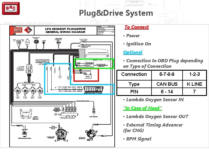
Plug&Drive System B R C G A S E Q U I P M E N T To Connect • Power • Ignition On Optional • Connection to OBD Plug depending on Type of Connection 6 -7 -8 -9 1 -2 -3 Type CAN BUS K LINE PIN 6 - 14 7 • Lambda Oxygen Sensor IN “In Case of Need” • Lambda Oxygen Sensor OUT • External Timing Advancer (for CNG) • RPM Signal
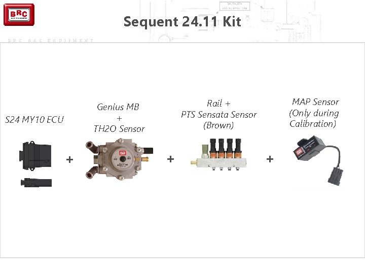
Sequent 24. 11 Kit B R C G A S E Q U I P M E N T S 24 MY 10 ECU + MAP Sensor (Only during Calibration) Rail + PTS Sensata Sensor (Brown) Genius MB + TH 2 O Sensor + +
Sequent 24. 11 System B R C G A S E Q U I P M E N T To Connect • Power • Ignition On • Rpm Signal or MAP Optional • Lambda Oxygen Sensor MAP Configuration - Not Connected (Only during calibration) -RPM Connected- Brc (DE 802042) - OEM (Original MAP Sensor)
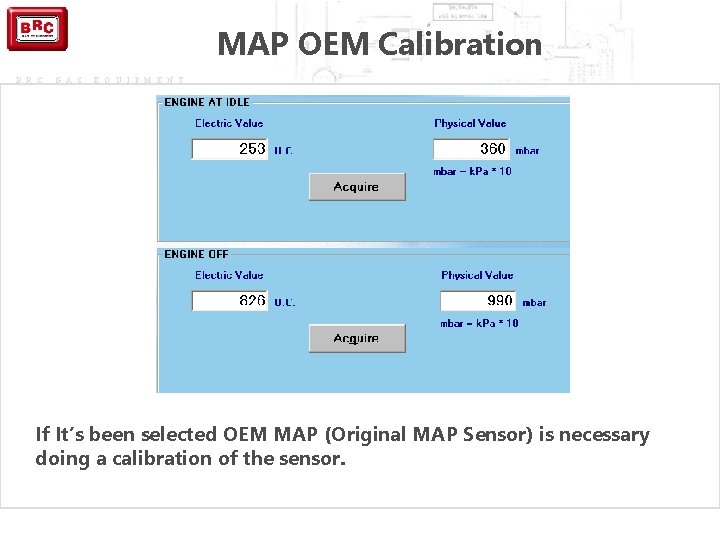
MAP OEM Calibration B R C G A S E Q U I P M E N T If It’s been selected OEM MAP (Original MAP Sensor) is necessary doing a calibration of the sensor.
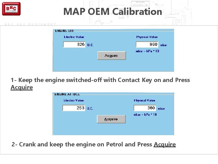
MAP OEM Calibration B R C G A S E Q U I P M E N T 1 - Keep the engine switched-off with Contact Key on and Press Acquire 2 - Crank and keep the engine on Petrol and Press Acquire
B R C G A S E Q U I P M E N T New Components
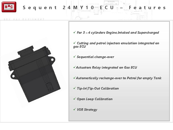
S e q u e n t B R C G A S 2 4 M Y 1 0 E C U – F e a t u r e s E Q U I P M E N T ü For 3 – 4 cylinders Engine, Intaked and Supercharged ü Cutting and petrol injectors emulation integrated on gas ECU ü Sequential change-over üActuators Relay integrated on Gas ECU üAutomatically rechange-over to Petrol for empty Tank ü Tip-InTip-Out Calibration ü Open Loop Calibration ü VSR Strategy
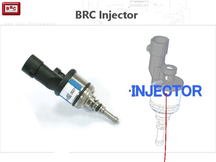
BRC Injector B R C G A S E Q U I P M E N T • INJECTOR
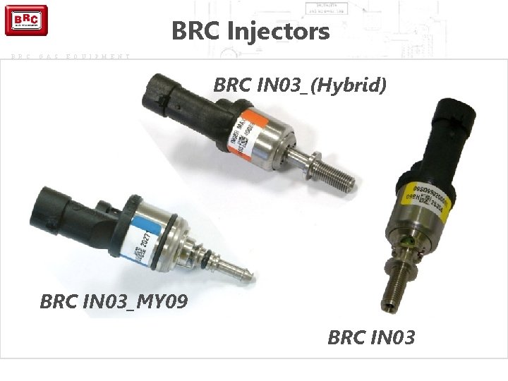
BRC Injectors B R C G A S E Q U I P M E N T BRC IN 03_(Hybrid) BRC IN 03_MY 09 BRC IN 03
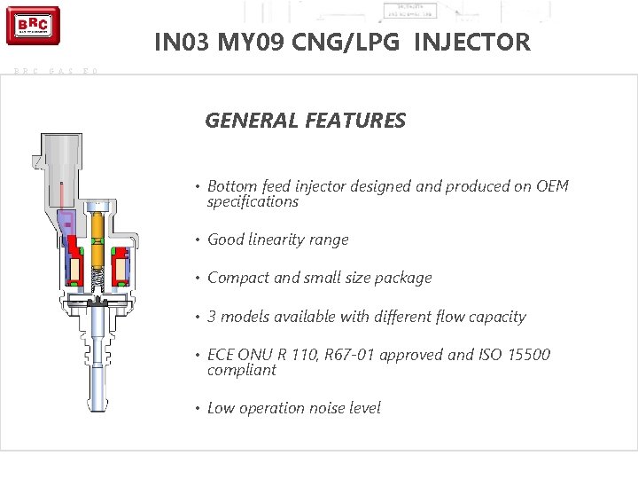
IN 03 MY 09 CNG/LPG INJECTOR B R C G A S E Q U I P M E N T GENERAL FEATURES • Bottom feed injector designed and produced on OEM specifications • Good linearity range • Compact and small size package • 3 models available with different flow capacity • ECE ONU R 110, R 67 -01 approved and ISO 15500 compliant • Low operation noise level
B R C G A S E Q U I P M E N T S 24. 11 New Strategies
Petrol Contribution Strategy (VSR) Sequent 24 MY 10 and Sequent 24. 11 Systems B R C G A S E Q U I P M E N T This strategy allows giving a petrol contribution during vehicle gas mode. Working condition (RPM, MAP) and petrol quantity to be injected can be calibrated through the new Plug & Drive Interface. It also allows protecting the life of valves seats, especially on vehicles suffering from this problem. !WARNING! VSR strategy does not assure feasibility of any kind of vehicles. The List of inadvisable vehicles is absolutely still valid and has priority on all feasibility confirmation or strategy.
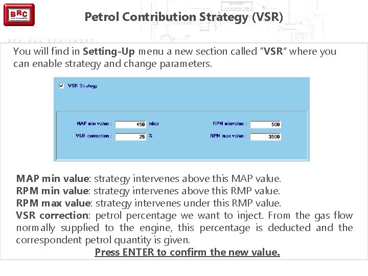
Petrol Contribution Strategy (VSR) B R C G A S E Q U I P M E N T You will find in Setting-Up menu a new section called “VSR” where you can enable strategy and change parameters. MAP min value: strategy intervenes above this MAP value. RPM min value: strategy intervenes above this RMP value. RPM max value: strategy intervenes under this RMP value. VSR correction: petrol percentage we want to inject. From the gas flow normally supplied to the engine, this percentage is deducted and the correspondent petrol quantity is given. Press ENTER to confirm the new value.
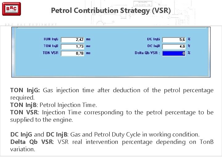
Petrol Contribution Strategy (VSR) B R C G A S E Q U I P M E N T TON Inj. G: Gas injection time after deduction of the petrol percentage required. TON Inj. B: Petrol Injection Time. TON VSR: Injection Time corresponding to the petrol percentage to be supplied to the engine. DC Inj. G and DC Inj. B: Gas and Petrol Duty Cycle in working condition. Delta Qb VSR: VSR real intervention percentage depending on Ton. B variation.
Start & Stop Strategy Sequent 24 MY 10 and Sequent 24. 11 Systems B R C G A S E Q U I P M E N T This strategy is dedicated to the vehicles equipped with Start & Stop. Peculiarity of this strategy is to reduce pollution and fuel consumption when vehicle stops, by switching the engine off. At any engine switching on, our system should wait for the right changeover parameters set up, burning so too much petrol. By enabling this strategy, above TGas and TH 2 O values defined, the vehicle starts the engine in gas forced mode without taking into consideration these emergency startings for computation. !Warning! For this strategy, RPM must be connected in crankshaft modality or RPM counter.
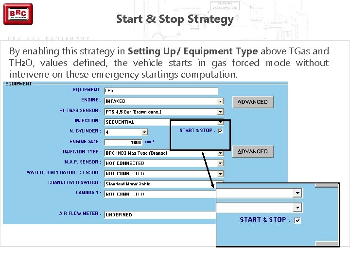
Start & Stop Strategy B R C G A S E Q U I P M E N T By enabling this strategy in Setting Up/ Equipment Type above TGas and TH 2 O, values defined, the vehicle starts in gas forced mode without intervene on these emergency startings computation.
B R C G A S E Q U I P M E N T SPECIAL STRATEGIES ALREADY IN EXISTENCE
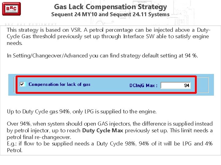
Gas Lack Compensation Strategy Sequent 24 MY 10 and Sequent 24. 11 Systems B R C G A S E Q U I P M E N T This strategy is based on VSR. A petrol percentage can be injected above a Duty. Cycle Gas threshold previously set up through Interface SW able to satisfy engine needs. In Setting/Changeover/Advanced you can find strategy default setting at 94 %. Up to Duty Cycle gas 94%, only LPG is supplied to the engine. Over 94%, when system should open GAS injectors, the difference is supplied instead by petrol injector, up to reach Duty Cycle Max previously set up. This limit needs a petrol final re-changeover. E. g. : if flow to be supplied needs a Duty Cycle 98%, 94% of it will be LPG and 4% Petrol.
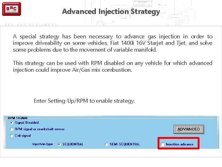
Advanced Injection Strategy B R C G A S E Q U I P M E N T A special strategy has been necessary to advance gas injection in order to improve driveability on some vehicles, Fiat 1400 i 16 V Starjet and Tjet, and solve some problems due to the movement of variable manifold. This strategy can be used with RPM disabled on any vehicle for which advanced injection could improve Air/Gas mix combustion. Enter Setting-Up/RPM to enable strategy.
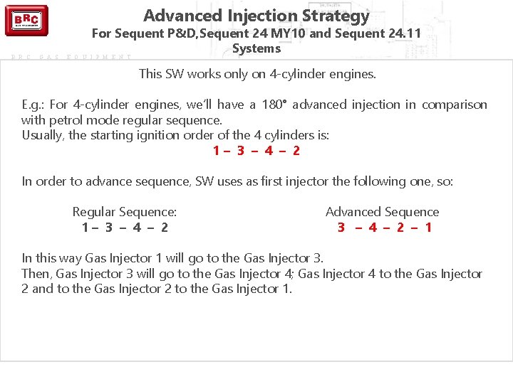
Advanced Injection Strategy B R C G A S For Sequent P&D, Sequent 24 MY 10 and Sequent 24. 11 Systems E Q U I P M E N T This SW works only on 4 -cylinder engines. E. g. : For 4 -cylinder engines, we’ll have a 180° advanced injection in comparison with petrol mode regular sequence. Usually, the starting ignition order of the 4 cylinders is: 1– 3 – 4 – 2 In order to advance sequence, SW uses as first injector the following one, so: Regular Sequence: 1– 3 – 4 – 2 Advanced Sequence 3 – 4 – 2 – 1 In this way Gas Injector 1 will go to the Gas Injector 3. Then, Gas Injector 3 will go to the Gas Injector 4; Gas Injector 4 to the Gas Injector 2 and to the Gas Injector 2 to the Gas Injector 1.
Advanced Injection Strategy B R C G A S E Q U I P M E N T for Sequent P&D, Sequent 24 MY 10 and Sequent 24. 11 Systems !Warning! (1) This strategy is not compatible with VSR and Gas Lack Compensation strategies.
Advanced Injection Strategy B R C G A S E Q U I P M E N T for Sequent P&D, Sequent 24 MY 10 and Sequent 24. 11 Systems !Warning! (2) This strategy cannot be used on Sequent 24 MY 07. To enable a similar strategy on this kind of systems, you need to advance manually the gas injection by acting directly on gas injectors connectors. Regular Sequence: 1– 3 – 4 – 2 Advanced Sequence: 3 – 4 – 2 – 1 So Gas Injector connector 1 will go to Gas Injector 3. Then Gas connector 3 will go to position 4; Gas connector 4 to position 2 and Gas connector 2 to position 1.
B R C G A S E Q U I P M E N T END OF LESSON: QUESTIONS & DOUBTS
- Slides: 32