
b KAGRA PSL Design Study Yuta Michimura Department

b. KAGRA PSL Design Study Yuta Michimura Department of Physics, University of Tokyo
Scope • Collect information for b. KAGRA PSL • Give first proposal for b. KAGRA PSL design • Start discussion on noises and control loops PMC, FSS, ISS • References: - JGW-G 1503293, JGW-G 1402866 (laser setup) - JGW-T 1402349 (i. KAGRA PMC) - JGW-G 1503515 (b. KAGRA PMC) - JGW-T 1503330 (FSS modeling) - JGW-D 1503389 (ISS plan) - JGW-D 1503189 (EOM layout plan) - JGW-T 1402332 (beam jitter requirement at PSL) - LIGO-T 0900649 (a. LIGO PSL Final Design) - N. Ohmae, Ph. D Thesis (2010) 2
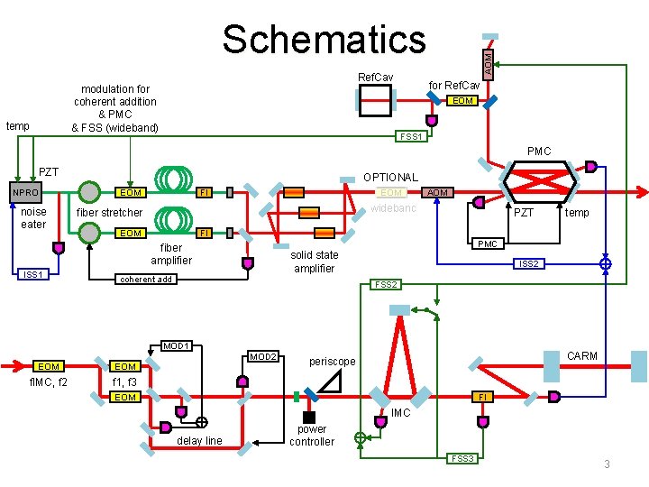
Ref. Cav modulation for coherent addition & PMC & FSS (wideband) temp AOM Schematics for Ref. Cav EOM FSS 1 PMC PZT NPRO noise eater OPTIONAL EOM FI wideband fiber stretcher EOM PZT PMC solid state amplifier coherent add ISS 2 FSS 2 MOD 1 MOD 2 EOM f. IMC, f 2 f 1, f 3 temp FI fiber amplifier ISS 1 AOM CARM periscope EOM FI IMC delay line power controller FSS 3 3
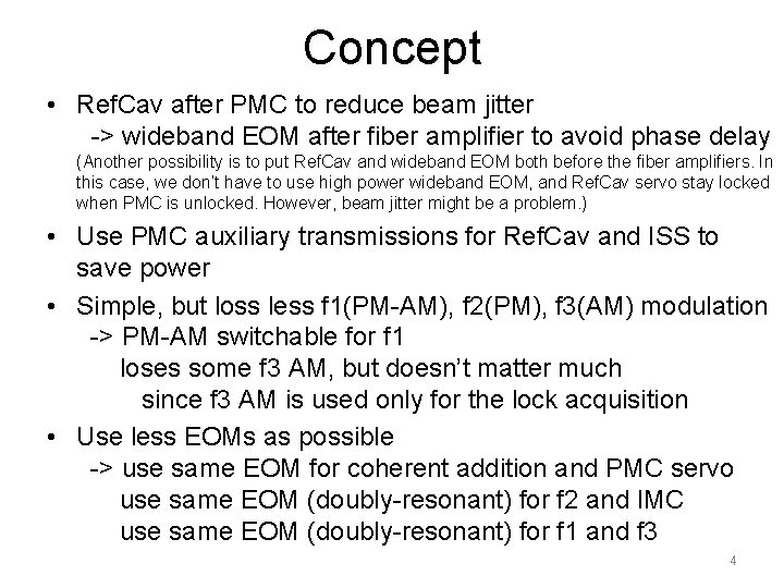
Concept • Ref. Cav after PMC to reduce beam jitter -> wideband EOM after fiber amplifier to avoid phase delay (Another possibility is to put Ref. Cav and wideband EOM both before the fiber amplifiers. In this case, we don’t have to use high power wideband EOM, and Ref. Cav servo stay locked when PMC is unlocked. However, beam jitter might be a problem. ) • Use PMC auxiliary transmissions for Ref. Cav and ISS to save power • Simple, but loss less f 1(PM-AM), f 2(PM), f 3(AM) modulation -> PM-AM switchable for f 1 loses some f 3 AM, but doesn’t matter much since f 3 AM is used only for the lock acquisition • Use less EOMs as possible -> use same EOM for coherent addition and PMC servo use same EOM (doubly-resonant) for f 2 and IMC use same EOM (doubly-resonant) for f 1 and f 3 4
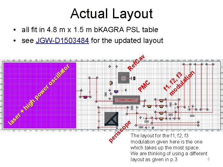
Actual Layout pe ris co f 1 m , f 2 od , ul f 3 at io n pe la se r + hi gh po w PM er o C sc ill at R or ef C av • all fit in 4. 8 m x 1. 5 m b. KAGRA PSL table • see JGW-D 1503484 for the updated layout The layout for the f 1, f 2, f 3 modulation given here is the one which takes up the most space. We are thinking of using a different 5 layout as given in p. 3
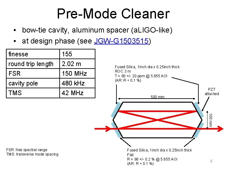
Pre-Mode Cleaner • bow-tie cavity, aluminum spacer (a. LIGO-like) • at design phase (see JGW-G 1503515) finesse 155 round trip length 2. 02 m FSR 150 MHz cavity pole 480 k. Hz TMS 42 MHz Fused Silica, 1 inch dia x 0. 25 inch thick ROC 3 m T = 80 +/- 20 ppm @ 5. 655 AOI (AR: R < 0. 1 %) 500 mm PZT attached 100 mm FSR: free spectral range TMS: transverse mode spacing Fused Silica, 1 inch dia x 0. 25 inch thick Flat R = 98 +/- 0. 2 % @ 5. 655 AOI (AR: R < 0. 1 %) 6
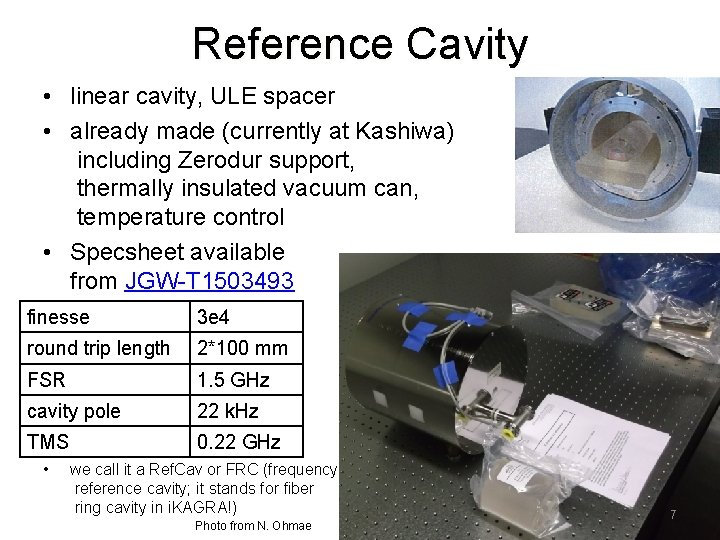
Reference Cavity • linear cavity, ULE spacer • already made (currently at Kashiwa) including Zerodur support, thermally insulated vacuum can, temperature control • Specsheet available from JGW-T 1503493 finesse 3 e 4 round trip length 2*100 mm FSR 1. 5 GHz cavity pole 22 k. Hz TMS 0. 22 GHz • we call it a Ref. Cav or FRC (frequency reference cavity; it stands for fiber ring cavity in i. KAGRA!) Photo from N. Ohmae 7
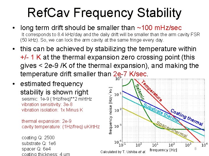
Ref. Cav Frequency Stability • long term drift should be smaller than ~100 m. Hz/sec It corresponds to 8. 4 k. Hz/day and the daily drift will be smaller than the arm cavity FSR (50 k. Hz). So, we can lock the arm cavity at the same fringe every day. seismic: 1 e-9 (1 Hz/freq)**2 m/rt. Hz vibration sensitivity: 3 e-8 vibration isolation: 1 x Minus K re tu ra pe m Te ic sm Sei • this can be achieved by stabilizing the temperature within +/- 1 K at thermal expansion zero crossing point (this gives < 2 e-9 /K of thermal expansion), and making the temperature drift smaller than 2 e-7 K/sec. • estimated frequency stability is shown right Su bst thermal expansion: 2 e-9 cavity temperature: (1 Hz/freq) u. K/rt. Hz coating Q: 2500 substrate Q: 1 e 6 spacer Q: 6 e 4 coating thickness: 4 um Calculated by T. Ushiba et al. Co a erm ting t her al ma Sp l ace r th erm al rat e th 8
Frequency Stabilization Servo • Modeling on going • See JGW-T 1503330 for preliminary result • It looks like the current PSL design basically meet the requirements 9
Intensity Stabilization Servo • No modeling yet • See JGW-D 1503389 10
Wideband EOM for FSS • We will use wideband EOMs before fiber amplifiers as a default plan (suggested by Rana Adhikari and Rick Savage) so, these wideband EOMs will be used for - coherent addition - PMC sidebands - FSS • In case phase delay is a problem for FSS, we will put another wideband EOM after solid state amplifier. This wideband EOM should be compatible with high power. 11
EOM Layout for f 1, f 2, f 3 Modulations • Calculation for deciding the layout on going • See JGW-D 1503189 (we are considering of choosing layout 3) • Sideband amplitudes we need f 1 PM: J 1(0. 15) [J 1(0. 2) at maximum] f 1 AM: 0. 65*J 1(0. 15) [optional for DRSE; 65% of PM] f 2 PM: J 1(0. 05) [J 1(0. 1) at maximum] f 3 AM: 0. 05 [only used for lock acquisition] • Unwanted sidebands f 1 harmonics: requirements to be calculated f 3 harmonics: requirements to be calculated unwanted f 1 AM: requirements to be calculated unwanted f 2 AM: requirements to be calculated 12
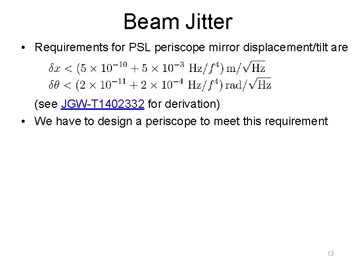
Beam Jitter • Requirements for PSL periscope mirror displacement/tilt are (see JGW-T 1402332 for derivation) • We have to design a periscope to meet this requirement 13
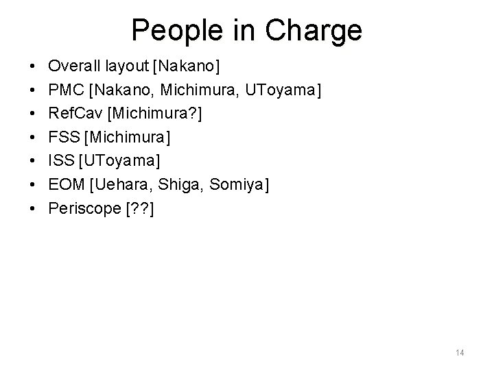
People in Charge • • Overall layout [Nakano] PMC [Nakano, Michimura, UToyama] Ref. Cav [Michimura? ] FSS [Michimura] ISS [UToyama] EOM [Uehara, Shiga, Somiya] Periscope [? ? ] 14
- Slides: 14