
b 0010 Time for Time ENGR x D
b 0010 Time for Time ENGR x. D 52 Eric Van. Wyk Fall 2012
Acknowledgements • Mark L. Chang lecture notes for Computer Architecture (Olin ENGR 3410) • Patterson & Hennessy: Book & Lecture Notes • Patterson’s 1997 course notes (U. C. Berkeley CS 152, 1997) • Tom Fountain 2000 course notes (Stanford EE 182) • Michael Wahl 2000 lecture notes (U. of Siegen CS 3339) • Ben Dugan 2001 lecture notes (UW-CSE 378) • Professor Scott Hauck lecture notes (UW EE 471) • Mark L. Chang lecture notes for Digital Logic (NWU B 01) • Texas Instruments Data Sheets
Today • The ravages of time • Latches, Flip Flops
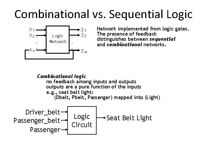
Combinational vs. Sequential Logic X 1 X 2 Xn- Logic Network - Z 1 Z 2 Network implemented from logic gates. The presence of feedback distinguishes between sequential and combinational networks. Zm Combinational logic no feedback among inputs and outputs are a pure function of the inputs e. g. , seat belt light: (Dbelt, Passenger) mapped into (Light) Driver_belt Passenger Logic Circuit Seat Belt Light
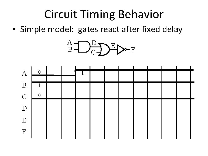
Circuit Timing Behavior • Simple model: gates react after fixed delay A B A 0 B 1 C 0 D E F D C 1 E F
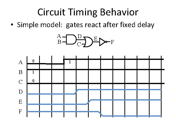
Circuit Timing Behavior • Simple model: gates react after fixed delay A B A 0 B 1 C 0 D E F D C 1 E F
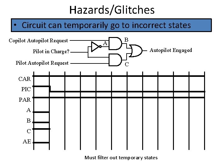
Hazards/Glitches • Circuit can temporarily go to incorrect states Copilot Autopilot Request A B Autopilot Engaged Pilot in Charge? Pilot Autopilot Request C CAR PIC PAR A B C AE Must filter out temporary states
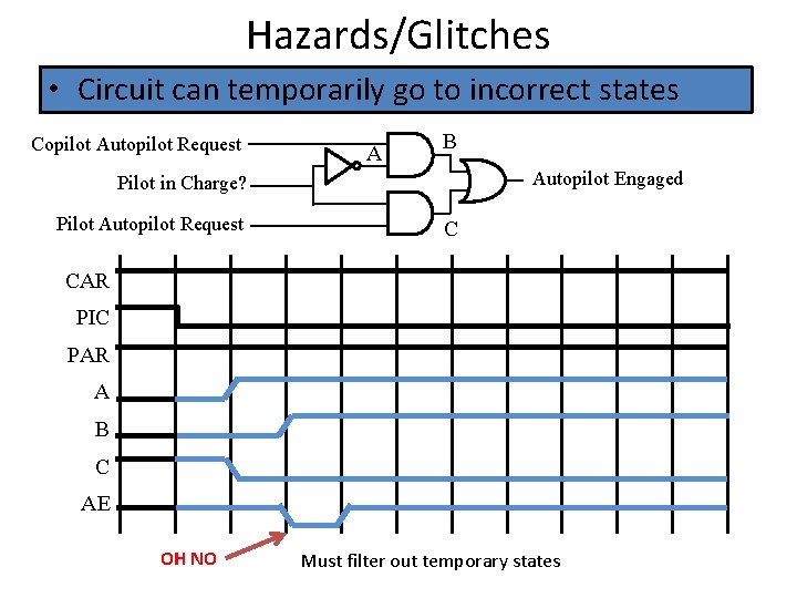
Hazards/Glitches • Circuit can temporarily go to incorrect states Copilot Autopilot Request A B Autopilot Engaged Pilot in Charge? Pilot Autopilot Request C CAR PIC PAR A B C AE OH NO Must filter out temporary states
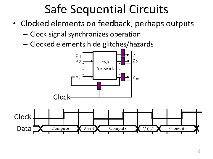
Safe Sequential Circuits • Clocked elements on feedback, perhaps outputs – Clock signal synchronizes operation – Clocked elements hide glitches/hazards X 1 X 2 - Xn - Logic Network - Z 1 Z 2 Zm Clock Data Compute Valid Compute 9
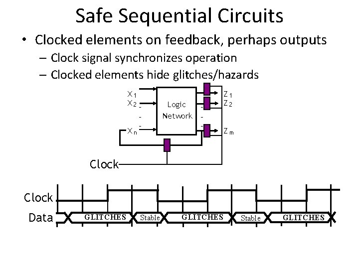
Safe Sequential Circuits • Clocked elements on feedback, perhaps outputs – Clock signal synchronizes operation – Clocked elements hide glitches/hazards X 1 X 2 - Xn - Logic Network - Z 1 Z 2 Zm Clock Data GLITCHES Stable GLITCHES
“Clocked” Elements • Two main categories: – Flip Flops and Latches • “Hold on” to state until triggered to update. • Many kinds
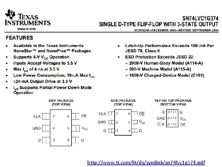
http: //www. ti. com/lit/ds/symlink/sn 74 lvc 1 g 374. pdf
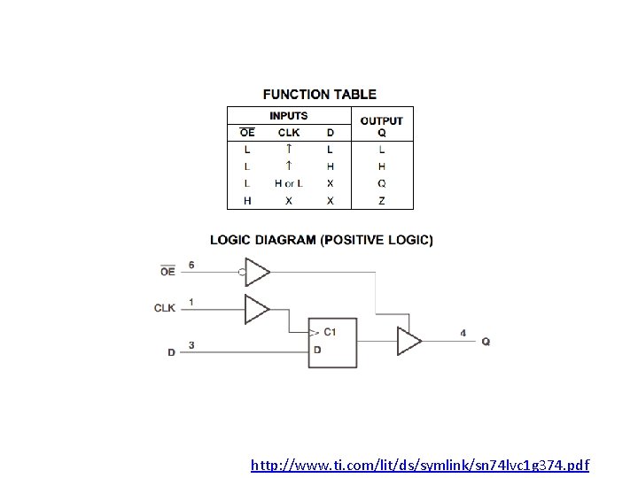
http: //www. ti. com/lit/ds/symlink/sn 74 lvc 1 g 374. pdf
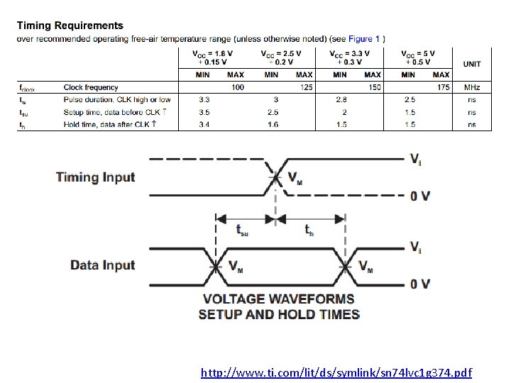
http: //www. ti. com/lit/ds/symlink/sn 74 lvc 1 g 374. pdf
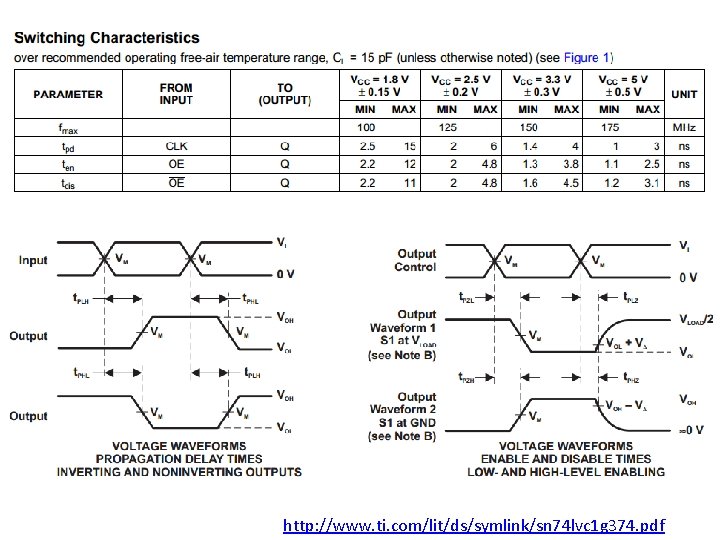
http: //www. ti. com/lit/ds/symlink/sn 74 lvc 1 g 374. pdf
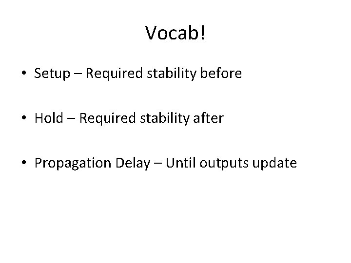
Vocab! • Setup – Required stability before • Hold – Required stability after • Propagation Delay – Until outputs update
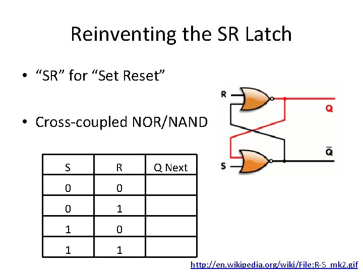
Reinventing the SR Latch • “SR” for “Set Reset” • Cross-coupled NOR/NAND S R 0 0 0 1 1 Q Next http: //en. wikipedia. org/wiki/File: R-S_mk 2. gif
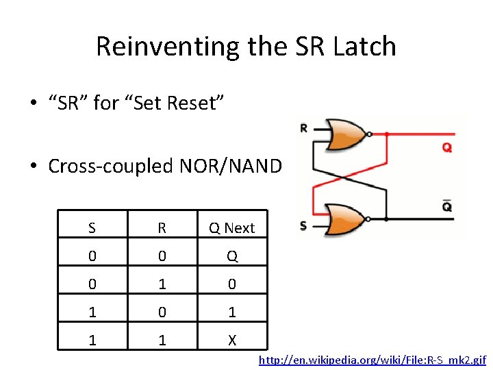
Reinventing the SR Latch • “SR” for “Set Reset” • Cross-coupled NOR/NAND S R Q Next 0 0 Q 0 1 0 1 1 1 X http: //en. wikipedia. org/wiki/File: R-S_mk 2. gif
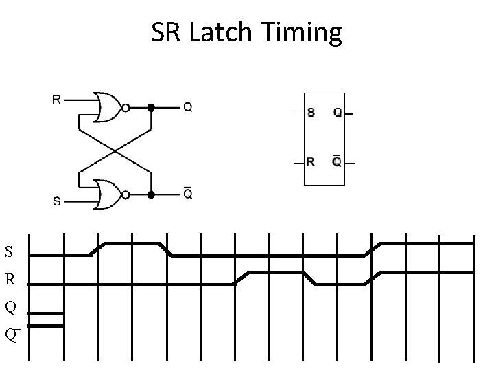
SR Latch Timing S R Q Q
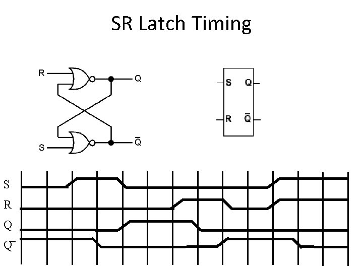
SR Latch Timing S R Q Q
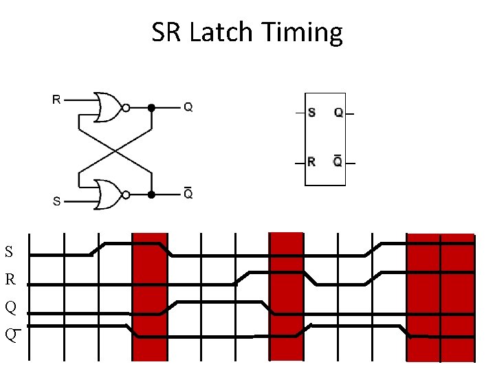
SR Latch Timing S R Q Q
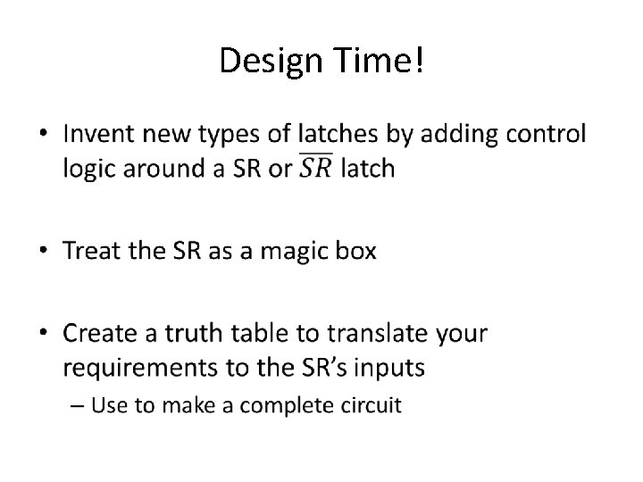
Design Time! •
Boards • Gated SR latch – Enable is True, S/R behave like a standard SR latch – When Enable is false, S/R have no effect • Outputs remain the same • Design a Gated D Latch – One Data input instead of Set Reset. – Output follows D input while enabled – When Enable is false, Output holds last value • Smallest design? Fastest?
You promised a Flop • Confusing vocab – they are similar • A latch is typically Enabled – Updates continuously or holds value • A Flip Flop is typically Clocked – Updates only at a specific moment • All are forms of ‘Bistable Multivibrators’
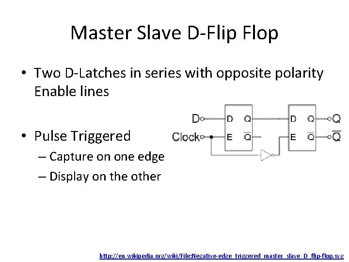
Master Slave D-Flip Flop • Two D-Latches in series with opposite polarity Enable lines • Pulse Triggered – Capture on one edge – Display on the other http: //en. wikipedia. org/wiki/File: Negative-edge_triggered_master_slave_D_flip-flop. svg
Edge Triggered D-Flip Flop • Functionally similar to Master Slave • Edge Triggered, not Pulse – Don’t waste half your clock period! • Construction highly process dependent – Can be roughly three SR Latches – Can be “Dynamic Logic” – Learn in VLSI
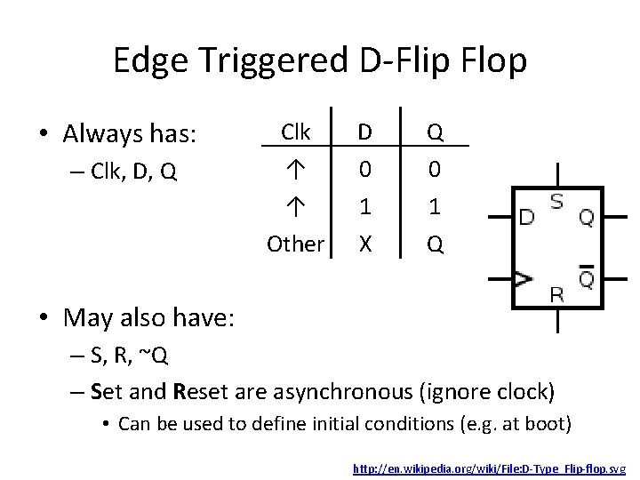
Edge Triggered D-Flip Flop • Always has: Clk D Q – Clk, D, Q ↑ 0 0 ↑ 1 1 Other X Q • May also have: – S, R, ~Q – Set and Reset are asynchronous (ignore clock) • Can be used to define initial conditions (e. g. at boot) http: //en. wikipedia. org/wiki/File: D-Type_Flip-flop. svg
Common Uses • In between processing stages • “Debounce” inputs – Hide external noise / uncertainty from the inputs • Synchronization
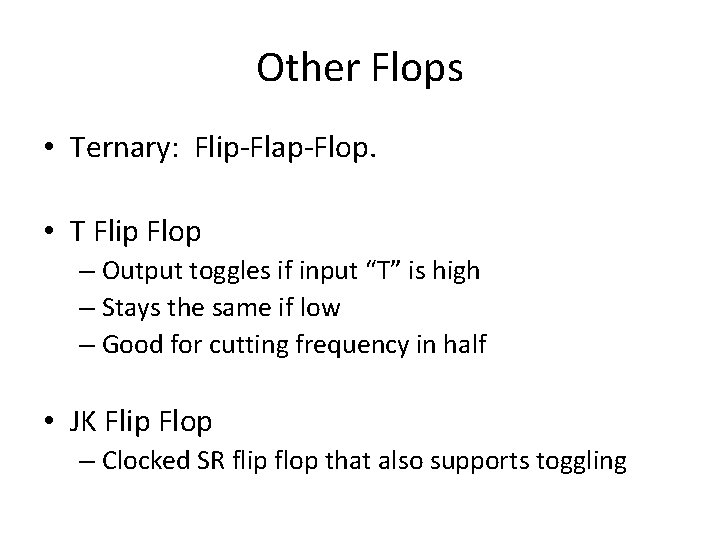
Other Flops • Ternary: Flip-Flap-Flop. • T Flip Flop – Output toggles if input “T” is high – Stays the same if low – Good for cutting frequency in half • JK Flip Flop – Clocked SR flip flop that also supports toggling
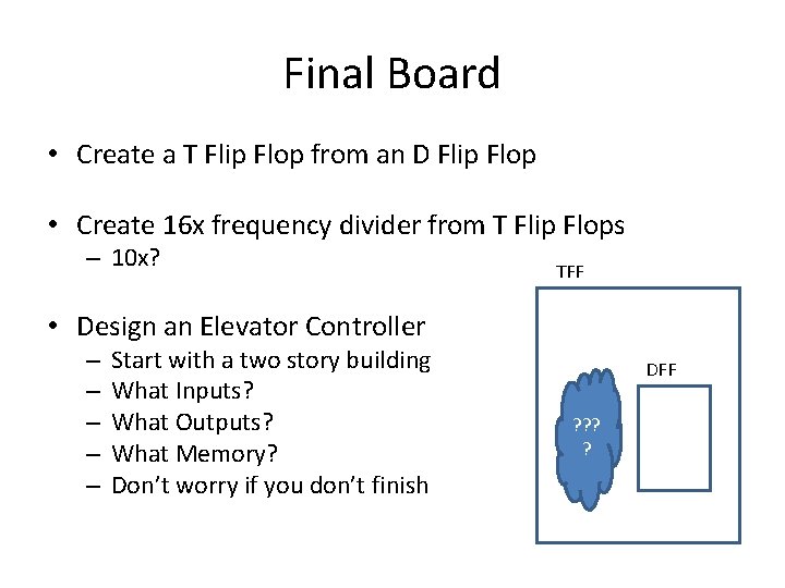
Final Board • Create a T Flip Flop from an D Flip Flop • Create 16 x frequency divider from T Flip Flops – 10 x? TFF • Design an Elevator Controller – – – Start with a two story building What Inputs? What Outputs? What Memory? Don’t worry if you don’t finish DFF ? ?
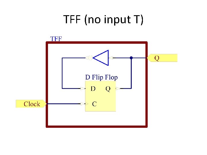
TFF (no input T)
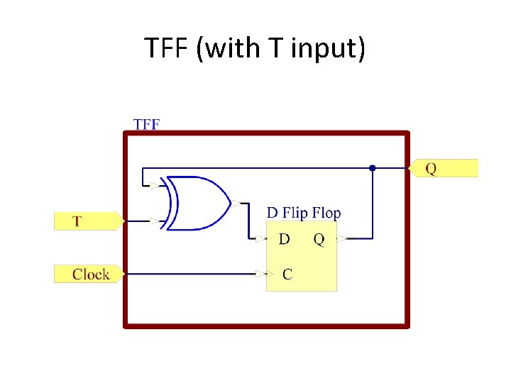
TFF (with T input)
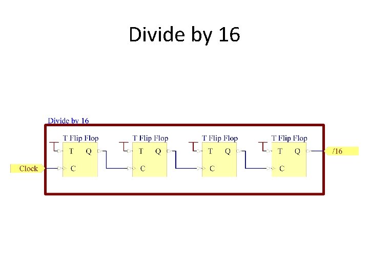
Divide by 16
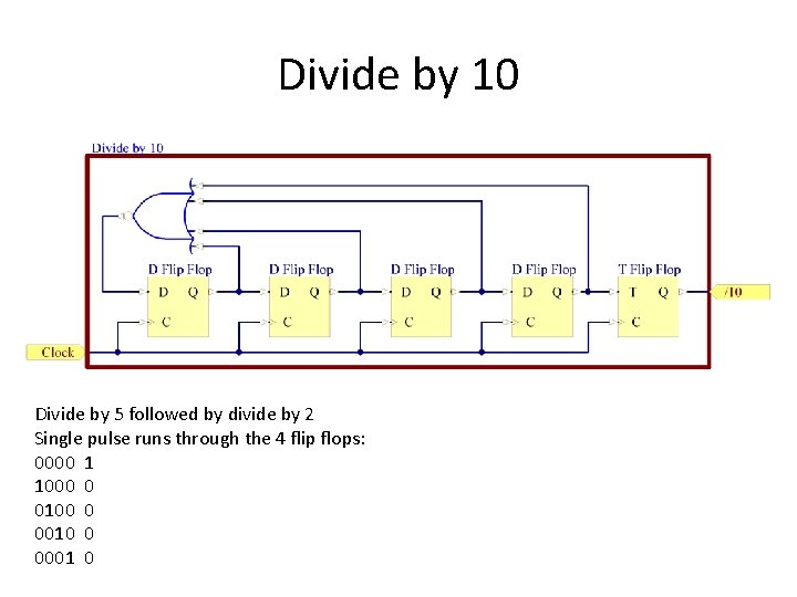
Divide by 10 Divide by 5 followed by divide by 2 Single pulse runs through the 4 flip flops: 0000 1 1000 0 0100 0 0010 0 0001 0
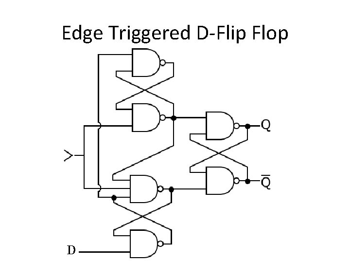
Edge Triggered D-Flip Flop
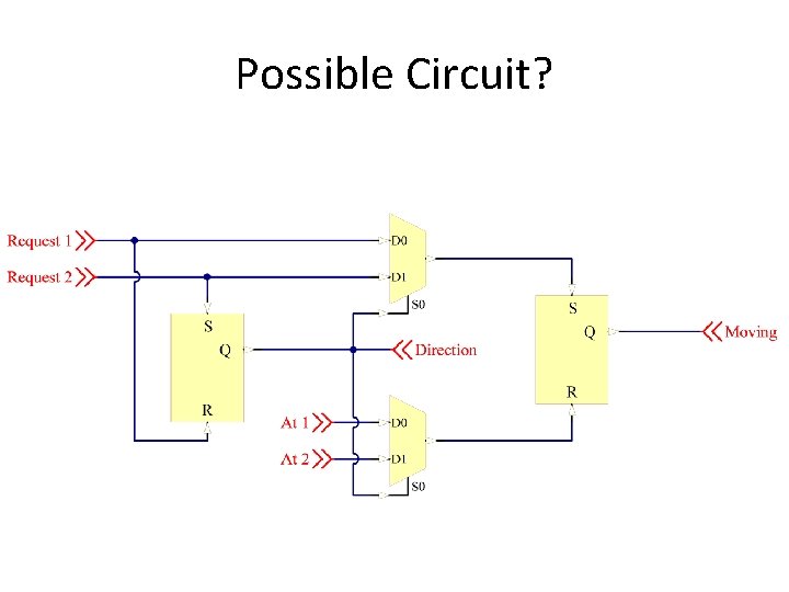
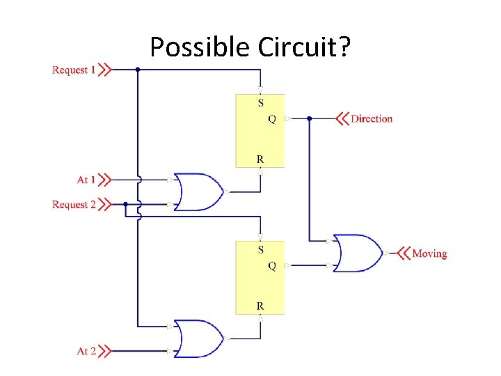
Elevator • Request Floor 1, Request Floor 2, At Floor 1, At Floor 2 • Moving, Direction
Possible Circuit?
Possible Circuit?
- Slides: 38