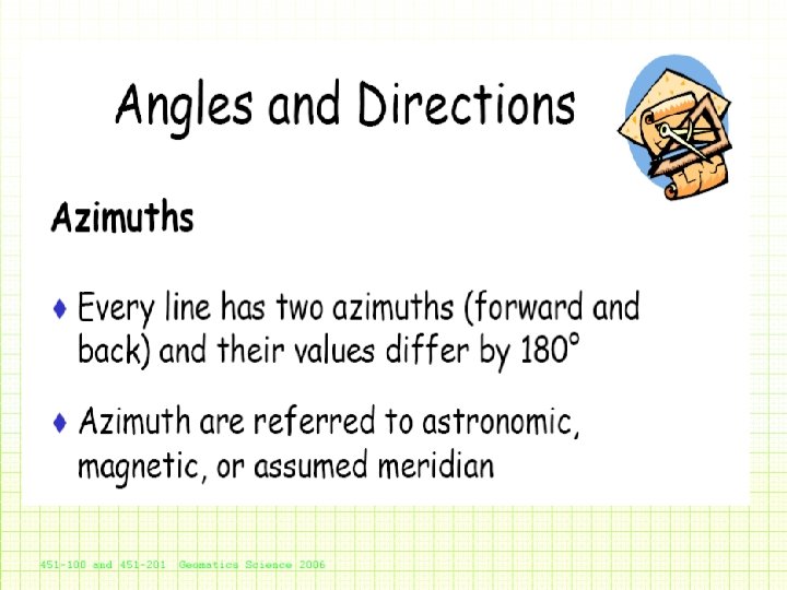
Azumith and Bearings Determination of angles and directions

Azumith and Bearings Determination of angles and directions

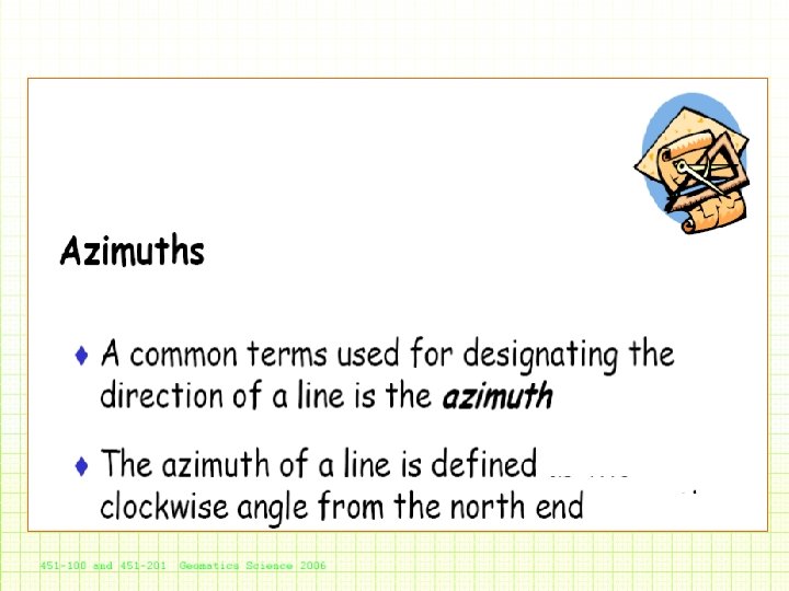
Bearing • The purpose of a bearing is to give an accurate indication of direction from one point to another. • Based on the magnetic properties. Free floating magnet indicates– NORTH • Simply, a bearing is a horizontal angle measured clockwise from a fixed reference line.

Locate the objects with Bearing and Distance Principle of Surveying O A F B C D E Bearing and Distance

Latitude and Longitude Prime Meridian Latitude Equator The spherical Earth is divided into a grid pattern using north-south lines (longitude) and east-west lines (latitude). The basic east west line is the Equator This is the zero line of latitude. Parallel lines above and below the equator are then drawn in. The poles are 90 o north and south of the equator. The basic north-south line is called the Prime Meridian, it is the zero line of longitude. It is drawn from the geographic north pole to the geographic south pole through Greenwich, England. Other north south lines are drawn in east and west of the prime meridian. Using this Latitude-Longitude grid, any point on the Earth’s surface can be defined by a location.

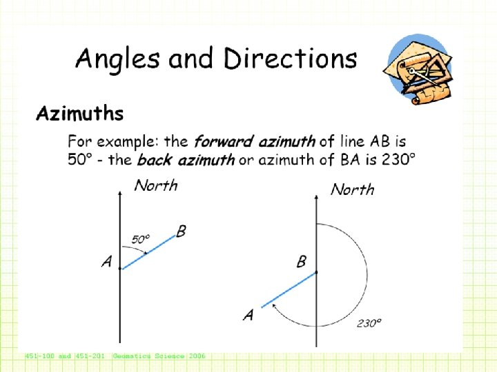
References Lines Or True North

Reference Meridians • True North –The astronomical North –The axis about which the Earth rotates –Associated with latitude and longitude • Magnetic North –Very unstable, handy for navigation • Assumed Reference - For rough mapping work

Meridians • A line on the mean surface of the earth joining north and south poles is called meridian. Geographic meridians are fixed, magnetic meridians vary with time and location. Relationship between “true” meridian and grid meridians

Reference Meridians • Are also associated with coordinate systems • Use a grid system • Can be treated as planar Cartesian system (x, y)

Common Types of Bearing • True Bearing – This type of bearing is used for mapping used Military and Army. – Bearings are measured w. r. t. true north using a compass. • Magnetic Bearing – This type of bearing is used for engineering surveying and mapping. – Bearings are measured w. r. t. magnetic north using a compass.
 or Azimuthal Bearing - Quadrental or")
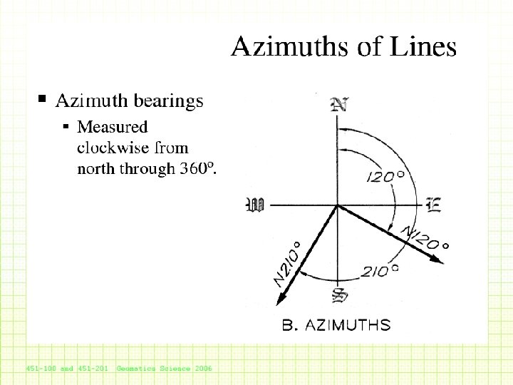
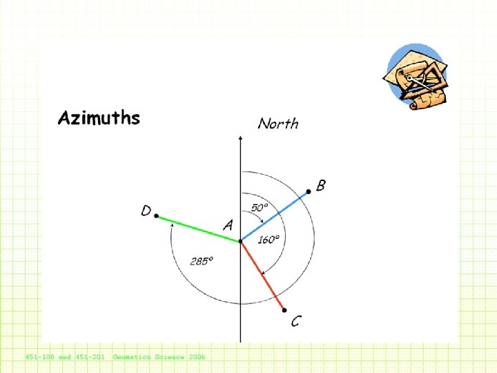
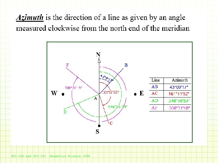
SYSTEMS OF BEARING - Whole Circle Bearing (WCB) or Azimuthal Bearing - Quadrental or Reduced Bearing (RB) WCB is the angle which a line makes with reference meridian, always measured from North in clockwise direction. Reduced Bearing is the smallest angle which a line makes with reference meridian, measured either clockwise or anticlockwise.

Reduced Bearings • The Reduced Bearing is always accompanied by letters that locate the quadrant in which the line falls (NE, NW, SE, or SW).

Reduced

RB
 of the lines")
Computation of Reduced Bearings • Thus, the whole circle bearings (WCB) of the lines must be converted into reduced bearings (RB), as RB is used in most computational work. W. C. B. (Between) Quadrant R. B. 0º to 90º NE W. C. B. 90º to 180º SE 180º-W. C. B. 180º to 270º SW W. C. B. -180º 270º to 360º NW 360º-W. C. B.
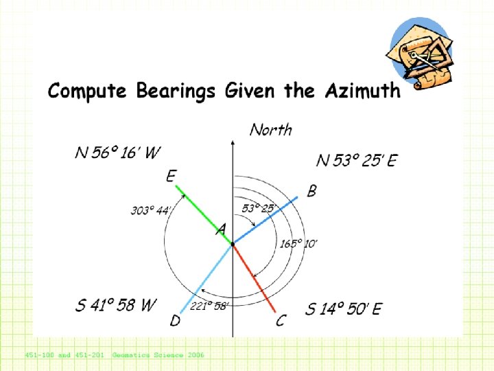

Conversion of WCB into RB and vice-versa. W. C. B. into R. B. into W. C. B Between Rule for R. B. Quadt 0º & 90º = θ 1 = WCB 90º & 180º = θ 2 = 180º-WCB SE S 180 -θ 2 E 180º & 270º = θ 3 WCB-180º SW S θ 3 -180 W = 180º+R. B. 180º & 270º θ 3 270º & 360º = θ 4 = 360º-WCB NW N 360 -θ 4 W = 360º-R. B. = 270º & 360º θ 4 NE R. B. N θ 1 E Rule for W. C. B. Between = R. B. = 0º & 90º θ 1 = 180º -R. B. = 90º & 180º θ 2

Compass • Many types & shapes. – Prismatic, Surveyor, Reflective & Silva • Consist of – Magnetised needle – A non-ferrous or plastic box 0 – A graduated 360 circle and – An aiming point

Parts of a Compass • Silva Compass

Types of Compasses generally used 1. PRISMATIC COMPASS 2. SURVEYOR’S COMPASS

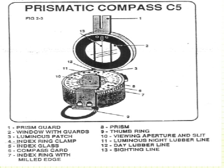
Prismatic Compass It is a pocket size instrument used for measuring magnetic bearings. 58

Prismatic Compass

Parts of a Prismatic Compass

Description of Parts 1 - Prism Guard 2 - Window with Guards 3 - Luminous Patch 4 - Index Ring Clamp 5 - Index Glass 6 - Graduated Compass Ring 7 - Index Ring with graduations 8 - Prism 9 - Thumb Ring 10 - Viewing Aperture & Slit 11 - Luminous Night Lubber Line 12 - Day Lubber Line 13 - Sighting Line
 – North = 0/360 –")
Graduation in Compass… • Degree system - (3600 circle) – North = 0/360 – South = 180 – East = 90 – West = 270 0 0

Graduated Compass Ring Synthetic, Translucent Material Inverted graduations

Graduated Compass Ring • The graduated ring 80 to 110 mm in diameter is made up of Aluminum. • It is divided into 360 equal parts. • The graduations are marked to half a degree. • The scale is inverted and can only be correctly viewed through the prism.

The Prism • The prism assembly is hinged. When the compass is opened, the prism is swung into the reading position over the index glass. The prism is also fitted to slides which enables it to be raised slightly for focussing. • The graduations of the compass ring is seen though the viewing aperture of the prism. Within the compass, directly below the prism and beneath the compass card, is a luminous source against which the compass card can be read at night.

Prismatic Compass • The main difference between Prismatic and Surveyor Compass is that the Surveyor's compass is usually the larger and more accurate instrument, and is generally used on a stand or tripod. • The prismatic compass is a small instrument which is generally hold in the hand for observing, and is therefore employed on the rougher classes of work. • The graduations on this prismatic compass are situated on a light aluminum ring fastened to the needle. The graduations therefore remain stationary with the needle, and the index turns with the sighting vanes.

Prismatic Compass • The prismatic attachment consists of a 45º reflecting prism with the eye vane so as to view the magnify image of the graduations on ring situated perpendicular to eye. • The prism can be moved up and down to provide an adjustment for focusing. • The image of the graduations is seen through a small circular aperture in the prism mounting, and immediately above this aperture is a small V cut on top of the mounting, over which the vertical wire in the object vane may be viewed.

Prismatic Compass • When the V cut, the vertical wire and the Ground point whose bearing is required are viewed in one line, the bearing is directly read off the graduated circle immediately underneath the vertical wire. • The two circular coloured discs in front of the back vane are dark glasses which can be brought in front of the vane when solar observations are being taken.

Prismatic Compass • Zero of the graduations coincides with the south point of the needle. • Since the circle is read at the observer's (rather than the target's) end, the graduations run clockwise from the south end of the needle (0º to 360º), whereas in the surveyor's compass, the graduations run anticlockwise from north.

• Point compass in the direction you want to go • Set the compass, and read the value that is touching the index arrow

Working with Compass - Centering Levelling Focussing Aiming at ground object Taking observations

Read a magnetic bearing • Open the compass and swing the prism to the reading position. • Hold compass steady so that graduated ring rotates freely. • Look through sighting slit and align sighting line on the object to which a bearing is required. • When graduated ring has come to rest, read the bearing through the viewing aperture on the prism.

Brunton Compass

Uses Mirror instead of Prism
 COMPASS PARTS and Features of a Lensatic compass Bezel Floating Dial Fixed")
BRUNTEN (LENSATIC) COMPASS PARTS and Features of a Lensatic compass Bezel Floating Dial Fixed Index Line Luminous Magnetic Arrow Luminous Sighting Dots Sighting Wire 3. LENS REAR SITE Sighting Slot Luminous Bezel Line Luminous Heading Lens Lanyard Ring Thumb Loop Graduated Straight Edge 1. COVER 2. BASE

LENSATIC COMPASS Cover • • • - Protects the floating dial and other parts of the compass when closed. Sighting Wire - front sight used with rear sight, for sighting landmarks for azimuth headings. Luminous Sighting Dots – used in low-light condition and night navigation. Also a visual queue on aligning your body with the compass during night navigation. Graduated Straight Edge - upper half of a standard 1: 50, 000 scale map ruler, for measuring distances on a map.

LENSATIC COMPASS Base - The main body of the compass. If, for any reason, the lensatic compass were to malfunction, the base would be the piece that you would want to still work. • • Bezel Ring – device clicks when turned; full 360° rotation is 120 clicks; each click equals 3°. Luminous Bezel Line – Used to mark a course direction during day or night navigation. Floating Dial – black scale (mils), red scale (degrees), set in a deep tub for global use. Luminous Heading – to read azimuth heading in low-light or night conditions. Luminous Magnetic Arrow – always points to magnetic north. Thumb Loop – to hold compass with the thumb. Fixed Index Line – azimuth heading. Lanyard Ring – for string or rope.

FLOATING DIAL SCALE BLACK RING Mils - is used mainly in artillery, tank, and mortar gunnery. AND is also used for very accurate azimuth land navigation. • 6400 Mils to a Circle • Distance Between Small Marks = 20 Mils • Distance Between Big Marks = 100 Mils • Distance Between Numbers = 200 Mils N = 64 (6400) E = 16 (1600) S = 32 (3200) W = 48 (4800) 8. 89 Mils = ½ Degree 17. 78 Mils = 1 Degree LENSATIC COMPASS

FLOATING DIAL SCALE BLACK RING Mils - is used mainly in artillery, tank, and mortar gunnery. AND is also used for very accurate azimuth land navigation. • 6400 Mils to a Circle • Distance Between Small Marks = 20 Mils • Distance Between Big Marks = 100 Mils • Distance Between Numbers = 200 Mils N = 64 (6400) E = 16 (1600) S = 32 (3200) W = 48 (4800) 8. 89 Mils = ½ Degree 17. 78 Mils = 1 Degree RED RING Degrees – common unit of measure is the degree (º). • 360 Degrees to a Circle • Distance Between Red Marks = 5º • Distance Between Big Marks = 10º • Distance Between Red Numbers = 20º N = 0º E = 90º S = 180º W = 270º

Sighting Through a Lensatic Compass • • Keep Eye Vane towards you and Object Vane towards Ground Object. Hold the Compass firmly.

Sighting Through a Lensatic Compass

Sighting Through a Lensatic Compass

PART 1 Basic Land Navigation Module 1 Lensatic Compass SIGHTING LENSATIC COMPASS

PART 1 Basic Land Navigation Module 1 Lensatic Compass SIGHTING LENSATIC COMPASS

SIGHTING THROUGH A LENSATIC COMPASS

Sighting Through a Lensatic Compass

Sighting Through a Lensatic Compass 65° Bearing

Types of Bearing • Fore Bearing • Back Bearing

FB and BB n The line • AB has a bearing of N 62 o 30’ E (FB) • BA has a bearing of S 62 o 30’ W (BB) Line Reverse Directions Bearing AB N 62 o 30’ E BA S 62 o 30’ W Reverse Bearings

Back Bearing • A back bearing is the bearing immediately opposite to the direction of travel. 0 • Add 180 if bearing is 0 smaller than 180 0 • Subtract 180 if bearing is larger than 0 180

Azimuth Reverse Direction n The line • CD has an azimuths of 128 o 20’ • DC has an azimuths of 308 o 20’ To reverse azimuths: add 180 o Line Azimuths CD 128 o 20’ DC 308 o 20’ Reverse Azimuth Bearings

Compass Survey of an Area • Mark corners of the Area to be surveyed • Take Bearing from first corner (A) to second (B) (Fore Bearing) • Shift at Point B - take a Bearing to Point A (Back Bearing) • Continue each subsequent points in this way

Other Methods of Finding Direction – – By shadow stick By sun observations By stars observations By GPS

Diagonal Eyepiece for astronomical observations

Diagonal Eyepiece • The diagonal eyepiece is required for sights to the zenith (for example, in field astronomy), when the horizontal plate obstructs access to the telescope and circle-reading eyepieces. • The eyepiece is attached to the telescope. It deflects the line of sight through 90°, so that the observer views the images from the top or side of the telescope. • When changing from one telescope position to the other, they can be reversed. The regular eyepiece of the telescope is unscrewed and replaced with these diagonal attachments.

Bearing 1. Included Angle - the difference between two 2. Magnetic Declination – Horizontal angle between true and magnetic North. directions (Bearings)
 North Magnetic North")
Geographic (True) North Magnetic North

North Points • True north - TN – Earth spins on this axis • Magnetic north - MN – Compass needle points to magnetic north

Magnetic Meridians • Defined at a point by earth’s magnetic lines of force • Magnetic declination – It varies with location on earth

Magnetic Variation • Magnetic variation: – Variation between grid and magnetic north. • Four types of magnetic variation – Diurnal variation (upto 12 minutes) – Annual variation (0 -2 minutes) – Secular variation (150 -250 years) – Irregular variation (due to storms, volcanic eruptions, earthquakes etc)(1 -2 degree)

Difference between True Bearing and Magnetic Bearing • If magnetic bearing is greater than true bearing - west • If magnetic bearing is less than true bearing – east • Compass is considered calibrated once variation is determined.

Conversion of bearings • To convert Magnetic north into True north or vice versa, it is necessary to add or subtract the Magnetic Declination angle. • When magnetic north is west of True north, subtract the magnetic declination angle. • When magnetic north is east of True north, add the magnetic declination angle. True Bearing = Magnetic Bearing ± Mag. Dec. (E/W)

Example Magnetic North Magnetic Declination 30 West True North Magnetic Bearing 1010 Grid Beading 980 1010 30 West 980 A B Reference Object

Local Attraction are the local forces which affect a freely floating magnetic needle. • Local disturbances due to magnetic field • Usually constant at a point

Local Magnetic Attraction • Small Metal Objects – Objects such as buttons, rings or wristwatches can affect the accuracy of a magnetic compass. – These small objects introduce relatively small error; their presence tends to be easily overlooked. – To ensure accurate readings, these small metal objects must be removed from the person. – Radio remote control units may seriously affect compass readings.

Local Magnetic Attraction • Large Metal Objects: – These cannot be readily removed, the observer must maintain a safe distance from them. – Example – Magnetic rocks or iron ore, Steel Structures, rails, Iron Pole, Electric Line, Pipe Line etc.

Corrections due to Local Attraction. Line F. B. B. AB 66º 20’ 246º 20’ BC 139º 30’ CD DA Corrections Corrected FB Corrected BB 0º at A 66º 20’ 246º 20’ 318º 50’ 0º at B 139º 30’ 319º 30’ 189º 40’ 11º 20’ + 0º 40’ at C 190º 20’ 10º 20’ 300º 30’ 119º 30’ - 1º at D 299º 30’ 119º 30’ Stations A and B are free from LA while Stations C and D are affected from LA

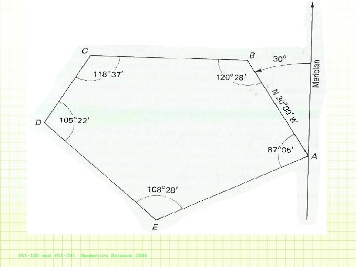
Computation of Bearings in a Traverse N N Q T s P R P S R Q Anti clockwise traverse T Clockwise traverse

Computation in a Traverse 1. 2. 3. 4. 5. Measure the bearings (Back and Fore) of the first traverse line (PT and PQ). Similarly measure the bearings (Back and Fore) of remaining traverse lines. Compute the included angles between the traverse lines. Calculation of closing error. Adjust the error.
 Start Given")
Counterclockwise Direction (1) Start Given
")
Counterclockwise Direction (2)
")
Counterclockwise Direction (3)
")
Counterclockwise Direction (4)
 Finish Check")
Counterclockwise Direction (5) Finish Check

Start Given Finish Check
 Start Given")
Clockwise Direction (1) Start Given
")
Clockwise Direction (2)
")
Clockwise Direction (3)
")
Clockwise Direction (4)
 Finish Check")
Clockwise Direction (5) Finish Check

Finish Check Start Given

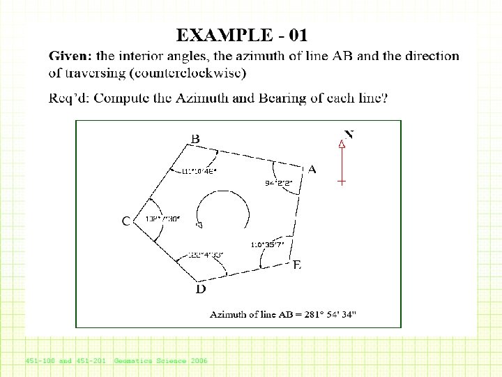
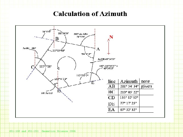
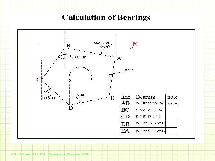
Azimuths Computation • Counterclockwise direction: add the interior angle to the back azimuth of the previous course Course BC CD DE EA AB Azimuths 270 o 28’ 209 o 05’ 134 o 27’ 62 o 55’ 330 o 00’ Bearing N 89 o 32’ W S 29 o 05’ W S 45 o 33’ E N 62 o 55’ E N 30 o 00’ W

Azimuths Computation • Clockwise direction: subtract the interior angle from the back azimuth of the previous course Course AE ED DC CB BA Azimuths 242 o 55’ 314 o 27’ 29 o 25’ 90 o 28’ 150 o 00’ Bearing S 62 o 55’ W N 45 o 33’ W N 29 o 05’ E S 89 o 32’ E S 30 o 00’ E

Bearing Computation • Computation can proceed in a Clockwise or counterclockwise Sketch for Bearings Computations

Comments on Bearing and Azimuths • Advantage of computing bearings directly from the given data in a closed traverse, is that the final computation provides a check on all the problem, ensuring the correctness of all the computed bearings

Sketch for each Bearings Calculation

Comments on Bearing and Azimuths • Disadvantages associated with computing bearings directly from the data in a closed traverse is that there is no systematic approach to the overall solution. Each bearing computation is unique, requiring individual analysis.

Comments on Bearing and Azimuths • The computation of azimuths involves a highly systematic routine: add (subtract) the interior angle from the back azimuths of the previous course.

Summary of Results from clockwise and counterclockwise approaches

Computation of Bearings in a Traverse using Deflection Angle N N Q T s P R P S R Q Anti clockwise traverse T Clockwise traverse

Compute Bearings of Remaining Traverse Lines from Deflection Angles • W. C. B. of a traverse line = W. C. B. of the preceding line ± deflection angle. • Use plus (+) for the right defection angles and minus (-) for the left deflection angles. • If the computed W. C. B. is more than 360º, subtract 360º, and if the result is negative add 360º to get the W. C. B. • Check W. C. B. of the last traverse line = W. C. B. of the starting line + ∑ (right defection angles) - ∑ (left deflection angles)

Computation • • Bearing PQ = 130º Bearing QP = 130º+180º = 310º Bearing QR = 310º+120º = 430º It is greater than 360º then Bearing QR = 430º-360º =70º Bearing RQ = 70º+180º = 250º Bearing RS = 250º+50º = 300º N S N N 130º P 50º 120º Q 70º 300º R
× 90º For")
Adjustment of a Traverse Sum of all Interior Angles = (2 n-4)× 90º For a 5 sided traverse Sum of all Angles = (10 -4)× 90º = 5400 Permissible closure error = 20”√n = 20”√ 5 → 45”

Compass Error Instrument Error – misalignment of Vane, Peep-site, Wire – inaccurate tic marks on compass circle External Error – “local influences” or “local attraction” User Error • compass not flat or moving

Advantage of a Compass – error limited to individual readings • not compounded from previous reading

THE END

Taking a Grid Bearing… • Using a compass & map. – Place edge of compass along intended bearing. – Direction arrow points the way you want to travel – Turn housing so meridian lines are parallel to easting lines – Read grid bearing where housing and index intersect Note: This bearing must be converted to mag’ bearing if intended for TIP Ignore the needle when using compass as a protractor

Application Plus Compass Variation East Magnetic Bearing Grid Bearing Less Compass Variation West

• Magnetic Bearings Compass backcont… bearings – Face the opposite direction, turn compass around & walk with directional arrow pointing towards you. – Or use white needle as directional indicator • Compass Error – Individual compasses – Local magnetic attraction due to steel/iron ore • • Transmission lines = 80 m Car = 60 m Wire fence = 10 m Pick, Axe or shovel = 3 m TIP The desk you’re sitting at has local magnetic attraction

Bearings - Cont’ N N X 31 A 0 a = 37 0 0 b = 75 AB = 31 if ‘A’ is specified 0 c = 304 37 C 0 N B N 304 0 75 0 A b

Magnetic Bearings • Setting a Magnetic bearing – Hold compass flat in palm – Set bearing on compass by rotating housing – Turn yourself till red needle lines up with north – Now walk in direction of directional arrow • Taking a Magnetic bearing – Hold compass with directional arrow pointing at intended object/direction – Rotate housing till north aligns with red arrow – Read bearing where index lines intersects

Magnetic Variation… • The difference between ‘grid north’ & ‘magnetic north’ is called magnetic variation. • The magnetic north pole is not fixed, it moves continually • Easterly & westerly variation • Check map for accuracy of variation

• • • Converting Bearings Mag’ bearings must be converted to Grid bearings for plotting. Grid Bearings taken from map must be converted to Mag’ for compass work To convert bearings – simply add or subtract variation GMS = Grid to Magnetic – Subtract (Grand. Ma Sux) MGA = Magnetic to Grid – Add (My Green Apple) Grid bearings are always larger than a magnetic bearing with an easterly variation

Prismatic Compass • When the V cut, the vertical wire and the Ground point whose bearing is required are viewed in one line, the bearing is directly read off the graduated circle immediately underneath the vertical wire. • The oblong mirror located in front of the forward vane slides up and down the vane, and is hinged to fold flat over it or to rest inclined at any angle with it. This mirror is used for solar observations, or for viewing any very high object, and is not a normal fitting to a compass. The two circular discs in front of the back vane are dark glasses which can be swung in front of the vane when solar observations are being taken.
- Slides: 117