AVR MAINTENANCE AND TESTING AUTOMATIC VOLTAGE REGULATOR AVR
 Friday, October 15, 2021 VG PATEL")
 v. Automatic voltage regulator (AVR)")


")
")
")
")
")


 FOLLOWING LOCATIONS")
 suggested by")
Isolate all A.")
Remove Stn. auxi.")


 Automatic voltage regulator (AVR) AVR 4) Crowbar")


- Slides: 43
AVR MAINTENANCE AND TESTING AUTOMATIC VOLTAGE REGULATOR (AVR) Friday, October 15, 2021 VG PATEL 1
AVR MAINTENANCE AND TESTING AVR AUTOMATIC VOLTAGE REGULATOR (AVR) v. Automatic voltage regulator (AVR) maintains the Generator terminal voltage at a given value automatically by changing the excitation current to the Generator field. v. The AVR supplies the required D. C. to the Generator field depending on the load, power factor etc. to maintain a constant terminal voltage. CONTROL SYSTEMS OF AVR 1. Auto control 2. Manual control Friday, October 15, 2021 VG PATEL 2
AVR MAINTENANCE AND TESTING AVR TYPES OF AVR 1. Single channel AVR v Two controllers one is automatic and the other is manual. v Both the controllers are fed from the same supply. 2. Dual channel AVR system v One automatic voltage controller and one manual controller v Different power supply, gate control and pulse amplifier units for each of the controllers Friday, October 15, 2021 VG PATEL 3
AVR MAINTENANCE AND TESTING AVR Function of AVR v compares the Generator terminal voltage with a preset reference voltage. v If the Generator terminal voltage is less than the reference voltage, the AVR increases D. C. voltage across the Generator field. v Maintaining the constant voltage as per the setting. Friday, October 15, 2021 VG PATEL 4
AVR MAINTENANCE AND TESTING AVR EXCITATION AS A CLOSED LOOP CONTROL SYSTEM If Synchronous Vg Generator Grid Excitation System The automatic voltage control system Friday, October 15, 2021 VG PATEL 5
AVR MAINTENANCE AND TESTING AVR OPERATIONAL AMPLIFIER FEED BACK GAIN 7 I N P U T 2 OP AMP 3 REF Friday, October 15, 2021 6 OUTPUT 4 VG PATEL
AVR MAINTENANCE AND TESTING AVR BLOCK DIAGRAM OF AVR Friday, October 15, 2021 VG PATEL 7
AVR MAINTENANCE AND TESTING AVR INPUTS v. Generator voltage feedback signal v. Generator voltage reference AVR provides the following functions and signals v Summing and amplification of signals to provide the exciter rectifier firing angle control signal. v. A signal for manual follow up. Friday, October 15, 2021 VG PATEL 8
AVR MAINTENANCE AND TESTING AVR ACTION v. Two inputs are of opposite polarity. v When the magnitudes are equal, the net input is zero. v When unequal-the error is amplified and reversed to obtain a correction signal which goes to the GPG (Gate Pulse Generator) Friday, October 15, 2021 VG PATEL 9
AVR MAINTENANCE AND TESTING AVR +/- 50 V SUPPLY To power the regulator amplifier as well as the optional accessories such as manual follow up and power integral stabilizer Regulator auxiliary card 3 phase voltage from the generator PTs are stepped down and applied to the regulator auxiliary card which converts it to ripple free dc voltage suitable for the input of regulator amplifier. Friday, October 15, 2021 VG PATEL 10
AVR MAINTENANCE AND TESTING AVR BALANCE VOLTMETER A 30 -0 -30 V DC voltmeter is connected across the output of regulator amplifier to read the magnitude and polarity of the output voltage of OP-AMP at any instant. Friday, October 15, 2021 VG PATEL 11
AVR MAINTENANCE AND TESTING AVR VOLTAGE SETTING From the +/- 50 V source, -50 V is applied and taken across a motorized potentiometer which can be operated from the control bench board. The variable output from the pot. is applied to the input of the regulator OP-AMP. Friday, October 15, 2021 VG PATEL 12
AVR MAINTENANCE AND TESTING AVR MANUAL VOLTAGE CONTROL • In the absence of AVR the voltage can be manually controlled. • The stabilized 15 V from the MPS is applied across a second potentiometer. The variable output goes to the GPG together with output of the regulator OP-AMP. Friday, October 15, 2021 VG PATEL 13
AVR MAINTENANCE AND TESTING AVR MANUAL FOLLOW UP When there is a noticeable output from the regulator OP-AMP, depending on its polarity, either of a pair of relays is automatically closed to drive the manual potentiometer motor in the required direction. Friday, October 15, 2021 VG PATEL 14
AVR MAINTENANCE AND TESTING AVR PREVENTIVE MAINTENANCE Ø Inspect the voltage regulator periodically to ensure that it is clean and free from accumulations of dust and moisture. Ø Be sure that all connections are clean and tight. Ø Ensure temperature of panel room below 40 Deg C. Friday, October 15, 2021 VG PATEL 15
AVR MAINTENANCE AND TESTING AVR PERIODIC TESTING Dummy Load Test: - Ø Measurement of the trigger pulses to the thyrister. Ø Verification of Output DC voltage wave form. Ø Checkout of all alarm circuits and protection trips. Friday, October 15, 2021 VG PATEL 16
AVR MAINTENANCE AND TESTING AVR-DVR TESTING 120 MW GENERATOR DVR PANEL MAINTENANCE AND TESTING REPORT 120 MW GENERATOR DVR DUMMY LOAD TEST (1) POWER SUPPLY MEASUREMENT (REGULATION CARDS) CARD NO. UN 0664 UNITROL KX 9170 a UNITROL OO 98 a LOCATIO N POWER SUPPLY + 5 V DC + 15 V DC - 15 V DC + 24 V DC AG 01 -- -- AG 10 -- -- AH 18 -- -- AA 01 AA 37 AB 01 Friday, October 15, 2021 VG PATEL + 48 V DC ---- 17
AVR MAINTENANCE AND TESTING AVR-DVR TESTING 120 MW GENERATOR DVR DUMMY LOAD TEST (2) CONTROL SUPPLY MEASUREMENT CONTROL SUPPLY CONTROL VOLTAGE 48 V DC UC UT UB Friday, October 15, 2021 220 V DC --- -- VG PATEL 18
AVR MAINTENANCE AND TESTING AVR-DVR TESTING 120 MW GENERATOR DVR DUMMY LOAD TEST (3) PULSE CHECKING: - (1) Pulse healthiness at individual Thyristor gate checked. (2) Pulse sequence ( R+, T-, S+, R-, T+, S-) verified and found OK. (3) Final DC output voltage wave form checked and all six pulses verified, found O. K. Friday, October 15, 2021 VG PATEL 19
AVR MAINTENANCE AND TESTING AVR-DVR TESTING 120 MW GENERATOR DVR DUMMY LOAD TEST (4) DUMMY LOAD TEST THYRISTOR BRIDGE-1 UC VOLTAGE CURRENT UC - 8. 3 - 6. 0 - 4. 0 - 2. 0 0 + 2. 0 + 3. 0 + 4. 0 + 5. 0 + 6. 0 + 7. 0 + 8. 0 Friday, October 15, 2021 THYRISTOR BRIDGE-2 VOLTAGE CURRENT VG PATEL BOTH THY. BRIDGE IN SERVICE UC VOLTAGE CURRENT 20
AVR MAINTENANCE AND TESTING AVR-DVR TESTING 120 MW GENERATOR DVR DUMMY LOAD TEST (5) FIELD BKR. /EXCITATION ON/OFF CONTROL & INDICATIONS TESTING: Local operation & various indications of Field bkr and Excitation at DVR PANEL tested and found O. K. Remote operation & various indications of Field bkr and Excitation at UCB tested and found O. K. Friday, October 15, 2021 VG PATEL 21
AVR MAINTENANCE AND TESTING AVR-DVR TESTING 120 MW GENERATOR DVR DUMMY LOAD TEST (6) PROTECTION SIMULATION PROTECTION GRP TO F. B. /EXCIT. TRIP SEE TO GRP/TURBINE TRIP SE TRANS. O/C STG. -1 ANN. SE TRANS. O/C (INST. ) TRIP TO F. B. Friday, October 15, 2021 RESULT OK OK VG PATEL PROTECTION RESULT ROTOR E/F STG. -1 ALARM OK ROTOR E/F STG. -2 TRIP OK THY. FUSE FAIL ANN. / TRIP OK LOSS OF COOLING ANN. OK 22
AVR MAINTENANCE AND TESTING AVR-DVR TESTING 120 MW GENERATOR DVR THYRISTOR PARAMETER MEASUREMENT SR. NO. THYRISTOR BRIDGE-1 1 2 3 4 5 6 A 1. 1 A 3. 1 A 5. 1 A 2. 1 A 4. 1 A 6. 1 Friday, October 15, 2021 GATE TO R-C NETWORK MEASUREMENT CATHODE CAPCITOR RESISTANCE IN MICRO IN OHM FARADS VG PATEL 23
AVR MAINTENANCE AND TESTING AVR-DVR TESTING 120 MW GENERATOR DVR THYRISTOR PARAMETER MEASUREMENT SR. NO. GATE TO CATHODE THYRISTOR BRIDGE-2 RESISTANCE IN OHM 1 2 3 4 5 6 Friday, October 15, 2021 R-C NETWORK MEASUREMENT RESISTANCE IN OHM CAPCITOR IN MICRO FARADS A 1. 2 A 3. 2 A 5. 2 A 2. 2 A 4. 2 A 6. 2 VG PATEL 24
AVR MAINTENANCE AND TESTING AVR-DVR TESTING 120 MW GENERATOR DVR THYRISTOR PARAMETER MEASUREMENT SR. NO. GATE TO CATHODE THYRISTOR BRIDGE-3 RESISTANCE IN OHM 1 2 3 4 5 6 Friday, October 15, 2021 R-C NETWORK MEASUREMENT RESISTANCE IN OHM CAPCITOR IN MICRO FARADS A 1. 3 A 3. 3 A 5. 3 A 2. 3 A 4. 3 A 6. 3 VG PATEL 25
AVR MAINTENANCE AND TESTING AVR-DVR MAINTENANCE 120 MW GENERATOR DVR PANEL MAINTENANCE REPORT Following maintenance and testing should be carried out in 120 MW Generator DVR panel during annual shutdown. (1) Thorough Cleaning of Regulation, Field flashing/Field breaker panel, Thyristor Bridge-1, 2 and 3 panels carried out by Vacuum cleaner. (2) POWER CONNECTION TIGHTNESS CHECKED AT FOLLOWING LOCATIONS (i) 415 V AC field flashing , 220 V DC input power cable terminations at FB panel. (ii) Static Excitation Transformer secondary cable termination at Thyristor bridge panels. (iii) AC/DC isolators and related bus connections. (iv) Field breaker and output DC bus connections. (v) Rotor power cable connections. Friday, October 15, 2021 VG PATEL 26
AVR MAINTENANCE AND TESTING AVR-DVR MAINTENANCE CONTROL CONNECTION TIGHTNESS CHECKED AT (3) FOLLOWING LOCATIONS (i) Power / control transformer terminals. (ii) Control cable termination at various terminal blocks. (iii) Current transformer input wires and different D. C. SHUNTS terminations. (iv) MCBs and transducers terminations. (v) Various INPUT/OUTPUT modules control terminations. (4) POLARITY REVERSAL: * Rotor polarity has been changed. (5) THYRISTOR PARAMETER MEASUREMENT Friday, October 15, 2021 VG PATEL 27
AVR MAINTENANCE AND TESTING AVR-DVR MAINTENANCE * TIPS FOR THYRISTOR MAINTENANCE (SOP) suggested by BHEL engineer. * Detail report is attached. (6) DUMMY LOAD TEST Detail report is attached. (7) PROTECTION SIMULATION Detail report is attached. REMOTE CONTROL OF FIELD BREAKER/ EXCITATION (8) & RELATED INDICATIONS AT UCB Detail report is attached. Friday, October 15, 2021 VG PATEL 28
AVR MAINTENANCE AND TESTING AVR-DVR MAINTENANCE AVR-DVR DUMMY LOAD TESTING PROCEDURE 1)Isolate all A. C. and D. C. control and power supply. 2)Switch off Thy. Bridge AC/DC isolators 3)Disconnect rotor power cables. 4)Switch off thy. Bridge cooling fan MCBs. 5)Remove field flashing D. C. power supply fuses F 38, F 39 ( FFcubi. ) 6)Remove field flashing A. C. power supply fuses F 48, F 49 and F 50 (FF cubi. ) 7)Remove Stn. auxi. 415 V A. C. power supply fuses F 43, F 44, F 45 (FF cubi. ) Friday, October 15, 2021 VG PATEL 29
AVR MAINTENANCE AND TESTING AVR-DVR MAINTENANCE AVR-DVR DUMMY LOAD TESTING PROCEDURE 1)Remove Stn. auxi. 415 V A. C. power supply fuses F 43, F 44, F 45 (FF cubi. ) 2)Remove field flashing relay K 24 type RE 300 ( REG. Cubi. ) 3)Remove Thy. Bridge cooling fans power supply fuses F 11 (THYcubi. ) Drg. No. GW 010/YS 003 4)Remove Regulation (Syn. ) power supply fuses F 15 (Thycubi. ) Drg. No. GW 010/YS 001 5)Remove internal wires of T. B. 48 FF, 49 FF and 50 FF. 6)Remove outgoing cable wires from T. B. 31 FF, 32 FF and 33 FF. 7)Loop 48 FF-31 FF, 49 FF-32 FF and 50 FF-33 FF and connect 415 V three phase power drawn from stn. auxi. Power supply T. B. 5 FF, 6 FF and 7 FF after ICTP switch. 8)Connect 415 V three phase power supply to outgoing terminal of Thy. Bridge -1 AC isolator from above switch. Friday, October 15, 2021 VG PATEL 30
AVR MAINTENANCE AND TESTING AVR-DVR MAINTENANCE AVR-DVR DUMMY LOAD TESTING PROCEDURE • Following interlocks are to be BYPASSED. • Disconnect any one wire from I/P module A 03 X 1 TB-1 and 2 (Thy. Bridge – 1 AC/DC isolator CLOSED i. e. ON) • Disconnect any one wire from I/P module A 03 X 1 TB-9 and 10 (Thy. Bridge – 2 AC/DC isolator CLOSED i. e. ON) • Disconnect any one wire from I/P module A 03 X 1 TB-17 and 18 (Thy. Bridge – 3 AC/DC isolator CLOSED i. e. ON) • Disconnect any one wire from I/P module A 04 X 1 TB-29 and 30 (Thy. Bridge Fan supply fuse healthy) • Get resetted micro switch of F 15 even its fuse links are out of its housing. (Reg. Power supply fuse healthy. ) • Short I/P module A 01 X 1 TB-25 and 26 ( Gen, speed > 90%) • Check NO contact at 42 R and 43 R of ULR RESET. • Check NO contact at I/P module A 02 X 1 TB- 7 and 8 ULR RESET. • Check NC contact at I/P module A 02 X 1 TB- 27 and 28 ULR RESET. • Make switch 1 ON of SW 865 of the Manual ch. -2 Card UN 0663 at AA 29 location. • Connect Dummy load with series amp. Meter and voltmeter at rotor cable bus bars. • Change POLARITY of rotor after completion of DUMMY LOAD test. Friday, October 15, 2021 VG PATEL 31
EXCITATION SYSTEMS CONTENTS 1. 2. 3. 4. Objectives Importance of Excitation Basic Generator Control Loops Types of Excitation Systems (a) D. C. Excitation System (b) Static Excitation System (c) Brushless Excitation System. 4. Generator Excitation Scheme of the 330 MW units. 5. Conclusion
OBJECTIVES 1. To explain the requirement of Excitation System 2. To explain the working of various excitation systems
IMPORTANCE OF EXCITATION • Regulation of terminal voltage, MVAR and power factor. • Regulation of load angle. • Ensuring protection of generator.
BASIC GENERATOR CONTROL LOOP ØAutomatic voltage regulator loop controls the magnitude of terminal voltage. PT AVR CT ØThe excitation is Controlling terminal voltage, MVAR and PF with suitable accuracy. Controller DC-Discharge Converter
TYPES OF EXCITATION SYSTEM 1. 2. 3. 4. D. C. Excitation System High Frequency (Rotating) Excitation System Static Excitation System Brushless Excitation System
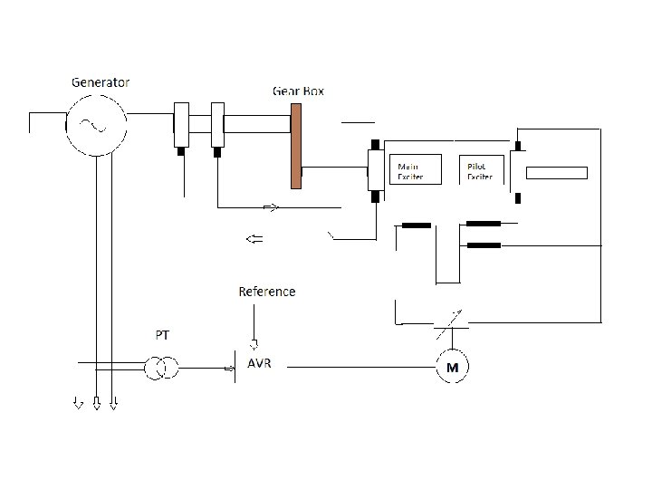
D. C. Excitation System ØIn this system exciter is d. c. commutator generator. ØExciter can be driven by direct coupling or through reduction gear. ØFirstly a relatively small rated output pilot exciter supplies the excitation for main exciter. Secondly the main exciter in turn supplies excitation to main generator rotor. ØPilot exciter’s output is regulated by variable resistance through motor driven rheostat, which is controlled via AVR. ~ SM = DC Exciter =
A. C. Excitation System Ø Types of A. C. Excitation System: 1. High Frequency Excitation (HFEX) System 2. Static Excitation System 3. Brushless Excitation System
STATIC EXCITATION SYSTEM 1. Main equipments: a. b. c. d. Rectifier transformer. Thyristor rectifier banks. Excitation startup and field discharge equipment. Regulation and operation control circuit. 2. Advantages: a. Fast Response b. More efficient and low maintenance
Excitation system main components Excitation transformer 1) Automatic voltage regulator (AVR) AVR 4) Crowbar Thyristor converter 3) Field breaker 2)
BRUSHLESS EXITATION SYSTEM • No slip rings and brushes. • PMG can be used as the pilot exciter. • Less maintenance required. • Generator Excitation Scheme of our 330 MW units.
CONCLUSION • Excitation system is an integral part of generator and thus of a power plant. So it knowledge is of utmost for every engineer working in the plant.