Autotuning Electronics for Varactor Tuned Flexible Interventional RF

Autotuning Electronics for Varactor Tuned, Flexible Interventional RF Coils Ross Venook, Greig Scott, Garry Gold, and Bob Hu

Introduction • Motivation – Why use interventional coils? – Why is this hard? • Background – History – RF coil tuning method(s) • What we tried – Modular electronics discussion • Results • Next steps

Why Use Interventional Coils? • Increased signal coupling & reduced noise coupling better SNR Coupled noise Coupled signal

Applications: Existing and Potential • Existing – Surface coils – Intravascular coils • Potential – Inter-articular – <add your application here>

SNR Comparison

Why Interventional Coils Are Harder to Use: Dynamic loading • Proximity works both ways – Closer coupling also means greater local tissue dependency – Requires deployability in some applications • Scaling works both ways – Human-scale effects are significant – Geometry more important

So… • Dynamic loading conditions require dynamic tuning to maximize SNR advantages with interventional coils • The tuning process should be automatic, and must add neither noise nor interference to the acquired signal
 are magnetic field coupling resonators")
“RF Coils” • RF transmitters and receivers (in MR) are magnetic field coupling resonators that are tuned to the Larmor frequency • Examples: – Saddle – Surface – Interventional

Resonance • ‘Parallel RLC’ circuit • Governing equation • Familiar result
![60 30 50 20 Reactance [Ohms] Resistance [Ohms] Impedance of Resonant Circuits 40 30](http://slidetodoc.com/presentation_image_h2/aa60607855a6e7ff19ee96856883c5ee/image-10.jpg "60 30 50 20 Reactance [Ohms] Resistance [Ohms] Impedance of Resonant Circuits 40 30")
60 30 50 20 Reactance [Ohms] Resistance [Ohms] Impedance of Resonant Circuits 40 30 20 0 -10 10 0 50 10 -20 55 60 65 Frequency [MHz] 70 75 -3050 55 60 65 Frequency [MHz] 70 75

Goals: Tuning and Matching • Tuning – Center Frequency near Larmor – Bandwidth appropriate to application • Matching – Tuned impedance near 50 + j 0 ohms
 •")
Complications • Loading the coil with a sample necessarily creates coupling (it better!) • Dynamic coupling creates dynamic tuning/matching conditions

Detuned Tuned
 • Automatic Tuning and Matching (Hwang and")
History • Tuning MRI coils (Boskamp 1985) • Automatic Tuning and Matching (Hwang and Hoult, 1998) • IV Expandable Loop Coils (Martin, et al, 1996)
 Cadaver")
Shoulders • Varactor Tuned Flexible Interventional Receiver Coils (Greig and Garry, ISMRM 2000) Cadaver Shoulder, 1. 5 T 3 D/SPGR/20 slices 6 cm FOV, 512 x 512

Greig’s Tunable Coil manual tune 150 p. F 20 K 10 K C 8 DC bias, RF isolate 9 V 20 K 75 n. H Flex coil 2. 5 cm Pull wire ~15 cm 2 turns C 8 <360 n. H 22 or 68 p. F Varactor Q spoil Rcv Port

Basic Tuning Method • Manually change DC bias on varactor • Maximize magnitude response – FID is a reasonable measure Drawbacks: • Requires manual iterative approach • Maximum FID may not correspond to maximum SNR • Feedback not effective for maximization
![60 30 50 20 Reactance [Ohms] Resistance [Ohms] A Better Method Using Phase 40](http://slidetodoc.com/presentation_image_h2/aa60607855a6e7ff19ee96856883c5ee/image-18.jpg "60 30 50 20 Reactance [Ohms] Resistance [Ohms] A Better Method Using Phase 40")
60 30 50 20 Reactance [Ohms] Resistance [Ohms] A Better Method Using Phase 40 30 20 0 -10 10 -20 50 55 60 65 Frequency [MHz] 70 75 -30 50 55 60 65 Frequency [MHz] • Zero-crossing at resonant frequency 70 75
![Resistance [Ohms] Reactance [Ohms] 20 50 10 40 30 10 -20 Resistance [Ohms] 55](http://slidetodoc.com/presentation_image_h2/aa60607855a6e7ff19ee96856883c5ee/image-19.jpg "Resistance [Ohms] Reactance [Ohms] 20 50 10 40 30 10 -20 Resistance [Ohms] 55")
Resistance [Ohms] Reactance [Ohms] 20 50 10 40 30 10 -20 Resistance [Ohms] 55 60 65 70 Frequency [MHz] 75 60 55 60 65 70 75 Frequency [MHz] Reactance [Ohms] 20 10 40 30 0 -10 20 10 -20 Resistance [Ohms] 55 60 65 70 Frequency [MHz] 75 60 50 55 Frequency [MHz] Reactance [Ohms] 30 20 50 10 40 30 0 -10 20 10 050 50 30 50 0 -10 20 050 At 63. 9 MHz 30 60 -20 55 60 65 70 Frequency [MHz] 75 50 55 Frequency [MHz]

Signal source Measuring Phase Offset Va Vb coil F->0 Vo>0 Cref + _ _ + Vo AD 835 250 MHz Multiplier Vo=|Va||Vb|cos(ωt) Vo ~ |Va||Vb|cos(Φ) + … F->90 Vo=0 Filter F->180 Vo<0

What We Tried

Phase Comparator Old New Vo Va Vb coil Cref + _ _ + Vo AD 835 250 MHz Multiplier Vo ~ |Va||Vb|cos(Φ) Filter Vo ~ cos(Φ)

Phase Detector Results Multiplier Output vs. Receiver Center Frequency Half-wavelength Txn Line
 • λ/4 • 3λ/8 • 5λ/8")
Phase Detector Results (cont…) • λ/4 • 3λ/8 • 5λ/8

Closed Loop Feedback? • Tempting… – Simple DC negative feedback about zero-point • …but unsuccessful – Oscillations – Railing • Phase detection scheme probably requires a different method (? )
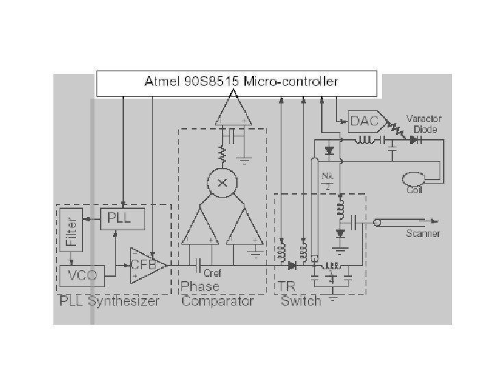

Microcontroller • Why use a microcontroller? – Controlling reference signal generation – Opportunity for tuning algorithms • Atmel AT 90 S 8515 – Serial Peripheral Interface – Analog Comparator – Simple

Atmel AT 90 S 8515 • Serial Peripheral Interface • Analog Comparator • Simple development platform – STK 500: Starter Kit – CVAVR: C compiler

Reference Signal Requirements • Accurate and stable reference signal at Larmor frequency during tuning • Signal well above Larmor frequency during receive mode
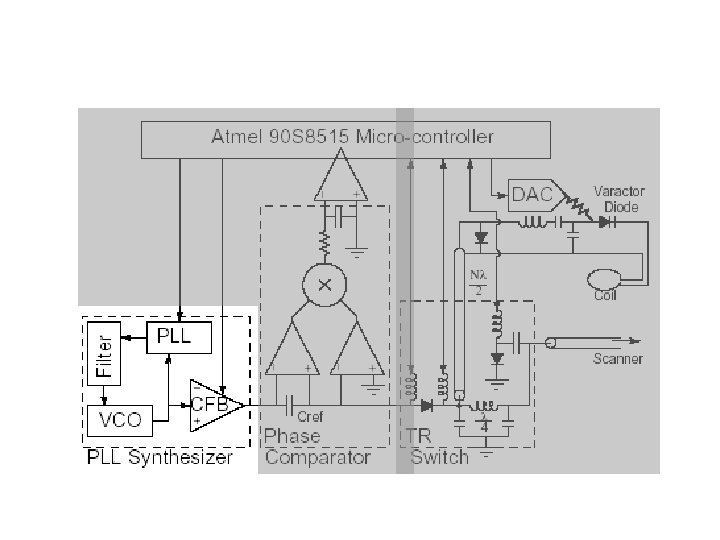

PLL Synthesizer • Phase Locked Loop – Frequency to voltage • Voltage-Controlled Oscillator – Voltage to frequency • Current Feedback Amplifier – “Tri-statable: ” turns off signal • Low Pass Filter – Cleans VCO output
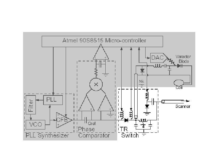

TR Switches • Loading effects categorically harmful • Ideal Tuning Circuit Scanner – Complete isolation of tuning and receiving circuitry

Actual TR Switches Microcontroller Scanner Tuning Circuit • PIN-diodes control signal direction • RF chokes ensure high-impedance, reduce loading

Complete System

Results • Basic tuning functionality – 300 ms total tuning time Retuned Detuned

Next Steps • Get an image with autotuned receiver on 1. 5 T scanner • SNR advantage (validation) experiments • Minimize tuning time • Explore VSWR bridge tuning – Remove need for λ/2 cable restriction
- Slides: 37