
Automotive Technology Principles Sixth Edition Diagnosis and Service

- Slides: 92
Automotive Technology Principles, Sixth Edition Diagnosis, and Service Chapter 83 Fuel Injection System Diagnosis and Service Copyright © 2018, 2015, 2011 Pearson Education, Inc. All Rights Reserved Copyright © 2020, 2016, 2012 Pearson Education, Inc. All Rights Reserved
LEARNING OBJECTIVES (1 of 2) 83. 1 Describe how to test fuel injectors. 83. 2 Describe how to test for an injector pulse and check fuel-injector resistance. 83. 3 Describe tests for pressure-drop balance, injector voltage-drop, and scope-testing fuel injectors. Copyright © 2020, 2016, 2012 Pearson Education, Inc. All Rights Reserved
LEARNING OBJECTIVES (2 of 2) 83. 4 Explain how to diagnose idle air speed control problems and fuel system problems. 83. 5 This chapter will help prepare for Engine Repair (A 8) ASE certification test content area “C” (Fuel, Air Induction, and Exhaust Systems Diagnosis and Repair). Copyright © 2020, 2016, 2012 Pearson Education, Inc. All Rights Reserved
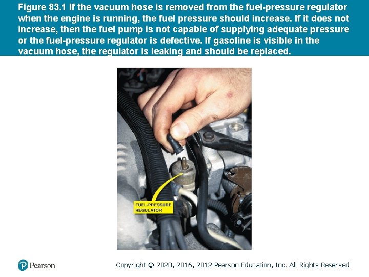
PORT FUEL INJECTION PRESSURE REGULATOR DIAGNOSIS • Connect a fuel-pressure gauge to monitor the fuel pressure. • Locate the fuel-pressure regulator and disconnect the vacuum hose from the regulator. • With the engine running at idle speed, reconnect the vacuum hose to the fuel-pressure regulator while watching the fuel pressure gauge. • Using a hand-operated vacuum pump, apply vacuum (20 inches Hg) to the regulator. Copyright © 2020, 2016, 2012 Pearson Education, Inc. All Rights Reserved
Figure 83. 1 If the vacuum hose is removed from the fuel-pressure regulator when the engine is running, the fuel pressure should increase. If it does not increase, then the fuel pump is not capable of supplying adequate pressure or the fuel-pressure regulator is defective. If gasoline is visible in the vacuum hose, the regulator is leaking and should be replaced. Copyright © 2020, 2016, 2012 Pearson Education, Inc. All Rights Reserved
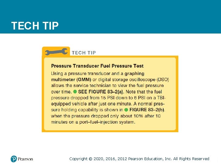
TECH TIP Copyright © 2020, 2016, 2012 Pearson Education, Inc. All Rights Reserved
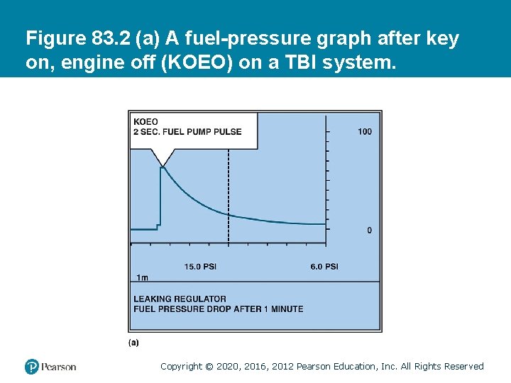
Figure 83. 2 (a) A fuel-pressure graph after key on, engine off (KOEO) on a TBI system. Copyright © 2020, 2016, 2012 Pearson Education, Inc. All Rights Reserved
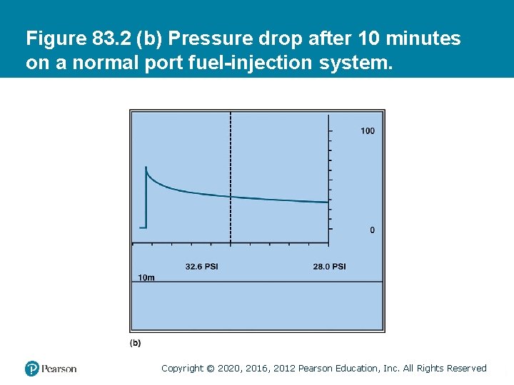
Figure 83. 2 (b) Pressure drop after 10 minutes on a normal port fuel-injection system. Copyright © 2020, 2016, 2012 Pearson Education, Inc. All Rights Reserved
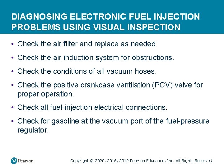
DIAGNOSING ELECTRONIC FUEL INJECTION PROBLEMS USING VISUAL INSPECTION • Check the air filter and replace as needed. • Check the air induction system for obstructions. • Check the conditions of all vacuum hoses. • Check the positive crankcase ventilation (PCV) valve for properation. • Check all fuel-injection electrical connections. • Check for gasoline at the vacuum port of the fuel-pressure regulator. Copyright © 2020, 2016, 2012 Pearson Education, Inc. All Rights Reserved
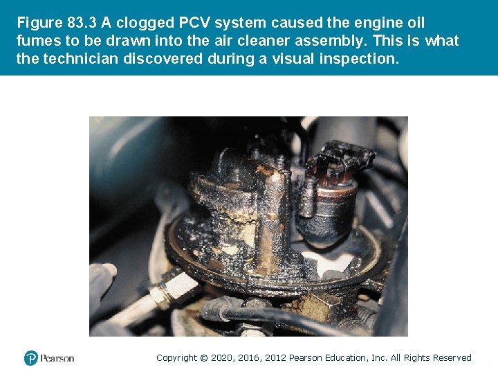
Figure 83. 3 A clogged PCV system caused the engine oil fumes to be drawn into the air cleaner assembly. This is what the technician discovered during a visual inspection. Copyright © 2020, 2016, 2012 Pearson Education, Inc. All Rights Reserved
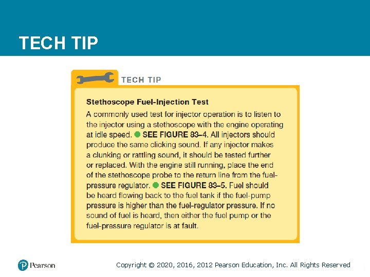
TECH TIP Copyright © 2020, 2016, 2012 Pearson Education, Inc. All Rights Reserved
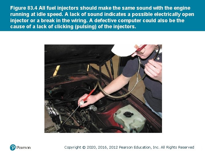
Figure 83. 4 All fuel injectors should make the same sound with the engine running at idle speed. A lack of sound indicates a possible electrically open injector or a break in the wiring. A defective computer could also be the cause of a lack of clicking (pulsing) of the injectors. Copyright © 2020, 2016, 2012 Pearson Education, Inc. All Rights Reserved
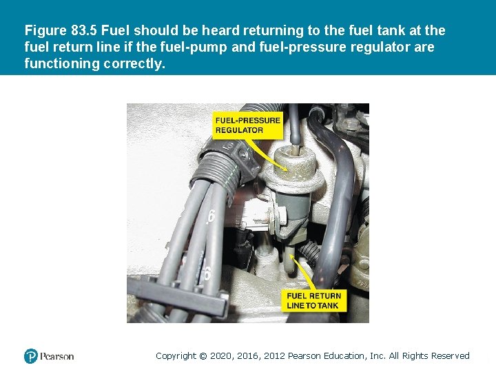
Figure 83. 5 Fuel should be heard returning to the fuel tank at the fuel return line if the fuel-pump and fuel-pressure regulator are functioning correctly. Copyright © 2020, 2016, 2012 Pearson Education, Inc. All Rights Reserved
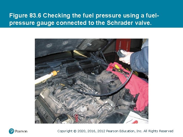
PORT FUEL INJECTION SYSTEM DAIGNOSIS • Attach a fuel-pressure gauge to the Schrader valve on the fuel rail. • Turn the ignition key on or start the engine to build up the fuel pump pressure (to about 35 to 45 PSI). • Wait 20 minutes and observe the fuel pressure retained in the fuel rail. Copyright © 2020, 2016, 2012 Pearson Education, Inc. All Rights Reserved
Figure 83. 6 Checking the fuel pressure using a fuelpressure gauge connected to the Schrader valve. Copyright © 2020, 2016, 2012 Pearson Education, Inc. All Rights Reserved
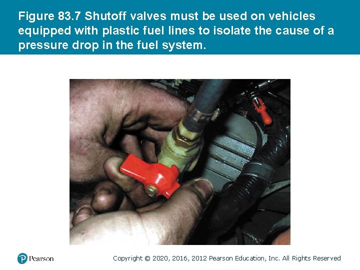
Figure 83. 7 Shutoff valves must be used on vehicles equipped with plastic fuel lines to isolate the cause of a pressure drop in the fuel system. Copyright © 2020, 2016, 2012 Pearson Education, Inc. All Rights Reserved
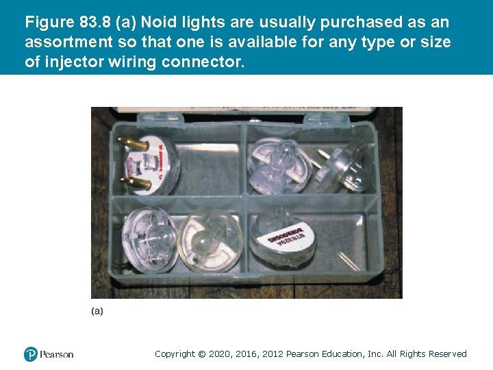
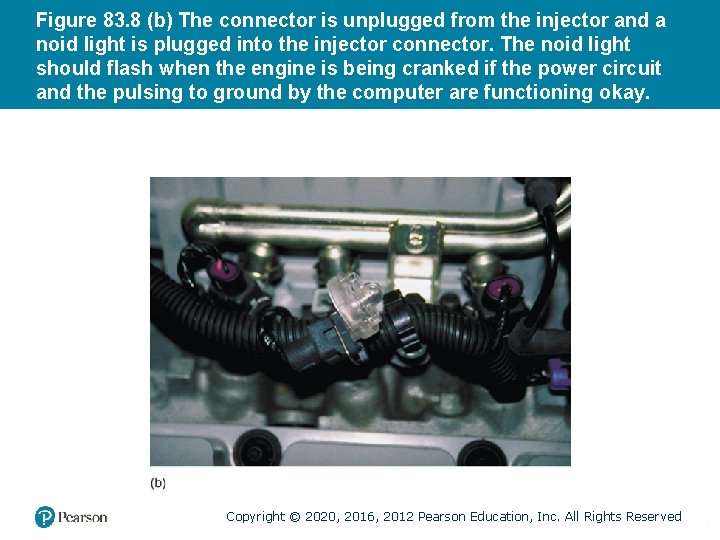
TESTING FOR AN INJECTOR PULSE • A noid light is designed to electrically replace the injector in the circuit and to flash if the injector circuit is working correctly. • Possible noid light problems and causes include the following: – The light is off and does not flash. – The noid light flashes dimly. – The noid light is on and does not flash. Copyright © 2020, 2016, 2012 Pearson Education, Inc. All Rights Reserved
Figure 83. 8 (a) Noid lights are usually purchased as an assortment so that one is available for any type or size of injector wiring connector. Copyright © 2020, 2016, 2012 Pearson Education, Inc. All Rights Reserved
Figure 83. 8 (b) The connector is unplugged from the injector and a noid light is plugged into the injector connector. The noid light should flash when the engine is being cranked if the power circuit and the pulsing to ground by the computer are functioning okay. Copyright © 2020, 2016, 2012 Pearson Education, Inc. All Rights Reserved
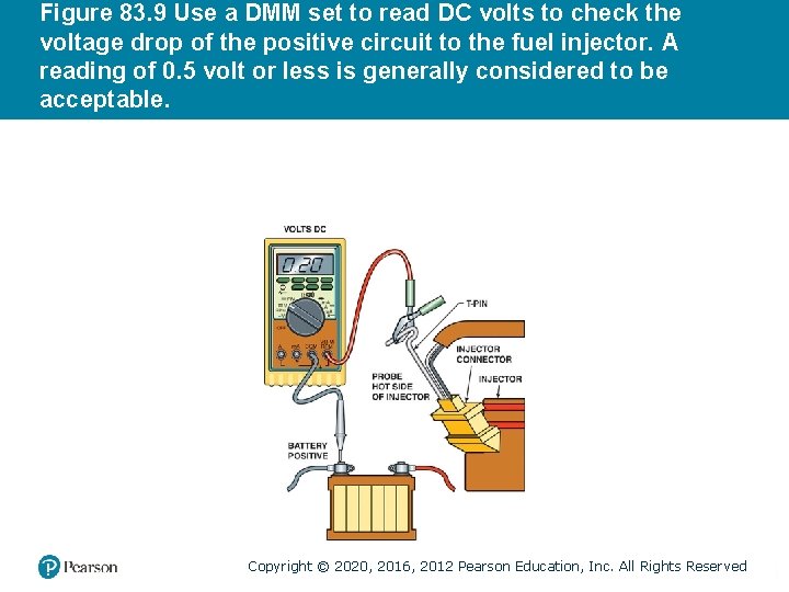
Figure 83. 9 Use a DMM set to read DC volts to check the voltage drop of the positive circuit to the fuel injector. A reading of 0. 5 volt or less is generally considered to be acceptable. Copyright © 2020, 2016, 2012 Pearson Education, Inc. All Rights Reserved
QUESTION 1: ? What is the purpose of a noid light? Copyright © 2020, 2016, 2012 Pearson Education, Inc. All Rights Reserved
ANSWER 1: To replace the injector in the circuit for the purpose of testing. Copyright © 2020, 2016, 2012 Pearson Education, Inc. All Rights Reserved
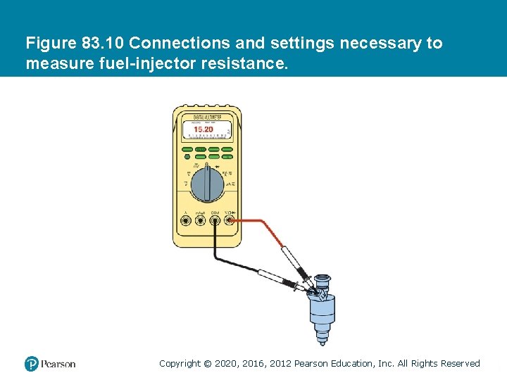
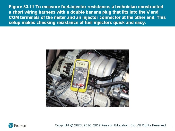
CHECKING FUEL INJECTOR RESISTANCE • With an ohmmeter, measure the resistance across the injector terminals. • Typical resistance values: – Low-resistance injectors: 1. 5 -4. 0 Ohms. – Higher-resistance injectors: 12 -16 Ohms. Copyright © 2020, 2016, 2012 Pearson Education, Inc. All Rights Reserved
Figure 83. 10 Connections and settings necessary to measure fuel-injector resistance. Copyright © 2020, 2016, 2012 Pearson Education, Inc. All Rights Reserved
Figure 83. 11 To measure fuel-injector resistance, a technician constructed a short wiring harness with a double banana plug that fits into the V and COM terminals of the meter and an injector connector at the other end. This setup makes checking resistance of fuel injectors quick and easy. Copyright © 2020, 2016, 2012 Pearson Education, Inc. All Rights Reserved
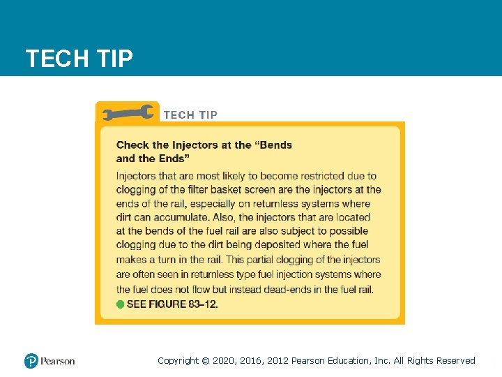
TECH TIP Copyright © 2020, 2016, 2012 Pearson Education, Inc. All Rights Reserved
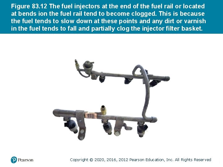
Figure 83. 12 The fuel injectors at the end of the fuel rail or located at bends ion the fuel rail tend to become clogged. This is because the fuel tends to slow down at these points and any dirt or varnish in the fuel tends to fall and partially clog the injector filter basket. Copyright © 2020, 2016, 2012 Pearson Education, Inc. All Rights Reserved
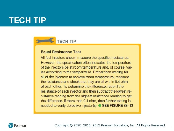
TECH TIP Copyright © 2020, 2016, 2012 Pearson Education, Inc. All Rights Reserved
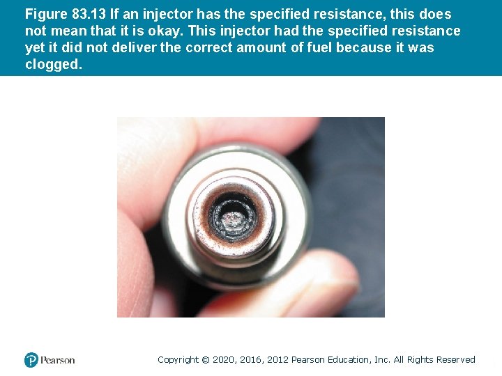
Figure 83. 13 If an injector has the specified resistance, this does not mean that it is okay. This injector had the specified resistance yet it did not deliver the correct amount of fuel because it was clogged. Copyright © 2020, 2016, 2012 Pearson Education, Inc. All Rights Reserved
PRESSURE DROP BALANCE TEST • The purpose of running this injector balance test is to determine which injector is restricted, inoperative, or delivering fuel differently. • The pressure balance test involves using an electrical timing device to pulse the fuel injectors on for a given amount of time, usually 500 milliseconds or 0. 5 seconds, and observing the drop in pressure that accompanies the pulse. Copyright © 2020, 2016, 2012 Pearson Education, Inc. All Rights Reserved
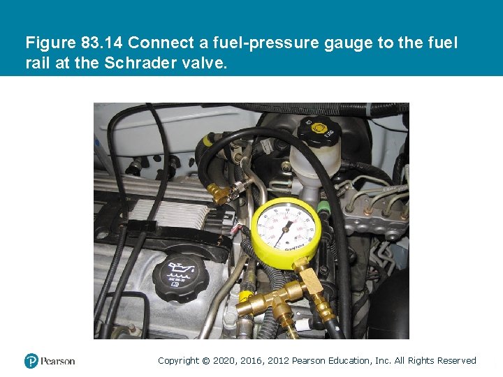
Figure 83. 14 Connect a fuel-pressure gauge to the fuel rail at the Schrader valve. Copyright © 2020, 2016, 2012 Pearson Education, Inc. All Rights Reserved
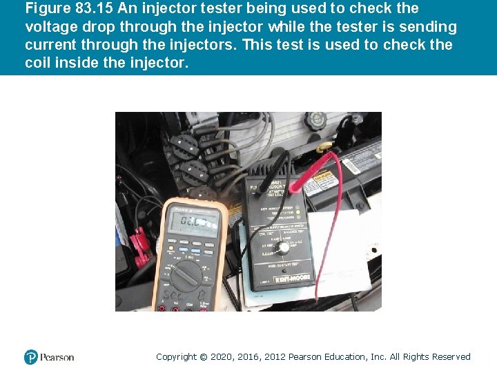
INJECTOR VOLTAGE DROP TESTS • Another test of injectors involves pulsing the injector and measuring the voltage drop across the windings as current is flowing. • The voltage drop across each injector should be within 0. 1 volt of each other. Copyright © 2020, 2016, 2012 Pearson Education, Inc. All Rights Reserved
Figure 83. 15 An injector tester being used to check the voltage drop through the injector while the tester is sending current through the injectors. This test is used to check the coil inside the injector. Copyright © 2020, 2016, 2012 Pearson Education, Inc. All Rights Reserved
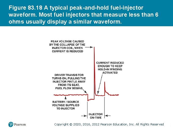
SCOPE TESTING FUEL INJECTORS • There are three types of injector drive circuits and each type of circuit has its own characteristic pattern. – Saturated Switch Type. – Peak and Hold Type. – Pulse-Width Modulated Type. Copyright © 2020, 2016, 2012 Pearson Education, Inc. All Rights Reserved
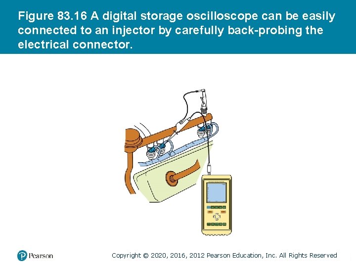
Figure 83. 16 A digital storage oscilloscope can be easily connected to an injector by carefully back-probing the electrical connector. Copyright © 2020, 2016, 2012 Pearson Education, Inc. All Rights Reserved
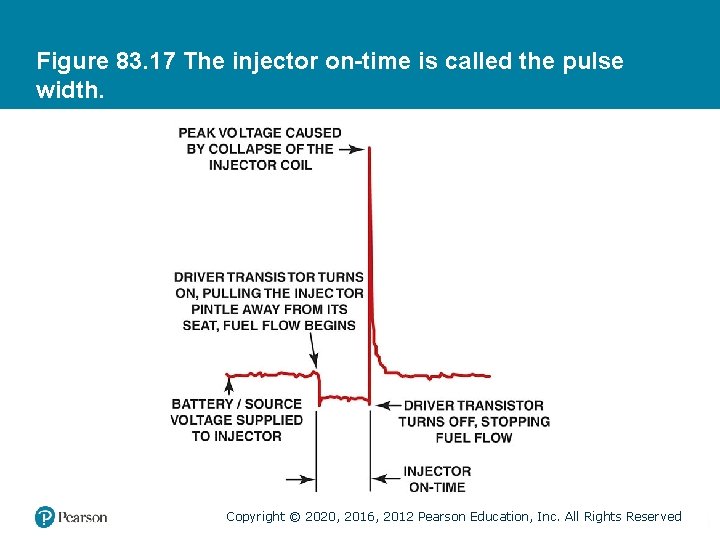
Figure 83. 17 The injector on-time is called the pulse width. Copyright © 2020, 2016, 2012 Pearson Education, Inc. All Rights Reserved
Figure 83. 18 A typical peak-and-hold fuel-injector waveform. Most fuel injectors that measure less than 6 ohms usually display a similar waveform. Copyright © 2020, 2016, 2012 Pearson Education, Inc. All Rights Reserved
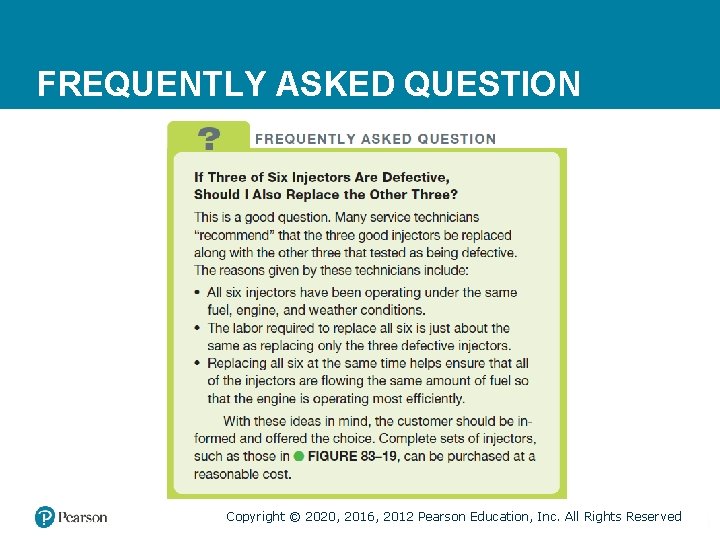
FREQUENTLY ASKED QUESTION Copyright © 2020, 2016, 2012 Pearson Education, Inc. All Rights Reserved
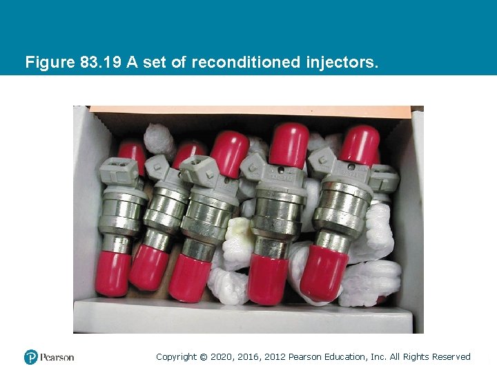
Figure 83. 19 A set of reconditioned injectors. Copyright © 2020, 2016, 2012 Pearson Education, Inc. All Rights Reserved
QUESTION 2: ? How can an injector be tested? Copyright © 2020, 2016, 2012 Pearson Education, Inc. All Rights Reserved
ANSWER 2: With a multimeter, a scan tool, pressure gauge, or an oscilloscope. Copyright © 2020, 2016, 2012 Pearson Education, Inc. All Rights Reserved
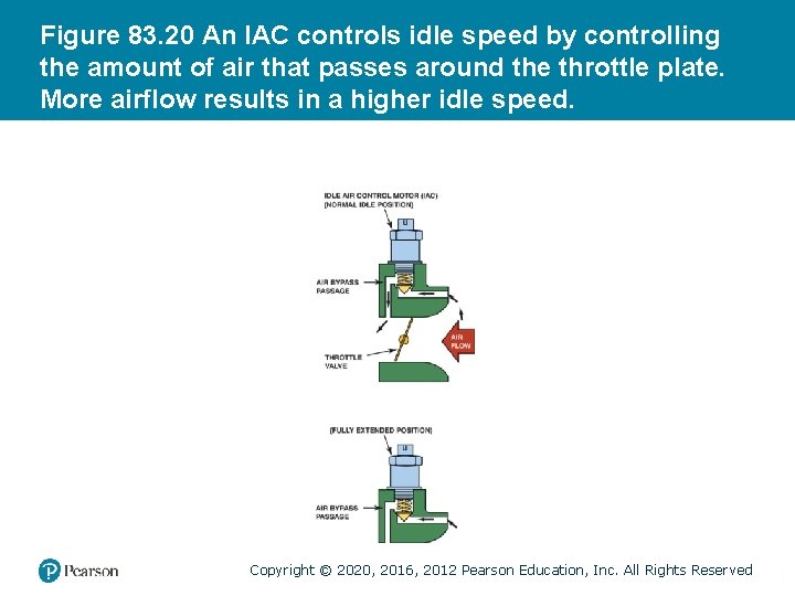
IDLE AIR SPEED CONTROL DIAGNOSIS • An electronic stepper motor or pulse-width modulated solenoid is used to maintain the correct idle speed. – When the engine stops, most IAC units retract outward to get ready for the next engine start. – As the engine gets warmer, the computer reduces engine idle speed gradually by reducing the number of counts or steps commanded by the IAC. – If the engine speed does not flare at start, then the IAC may not be working (it may be stuck in one position). Copyright © 2020, 2016, 2012 Pearson Education, Inc. All Rights Reserved
Figure 83. 20 An IAC controls idle speed by controlling the amount of air that passes around the throttle plate. More airflow results in a higher idle speed. Copyright © 2020, 2016, 2012 Pearson Education, Inc. All Rights Reserved
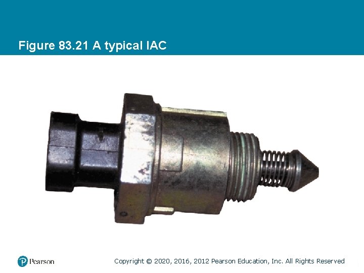
Figure 83. 21 A typical IAC Copyright © 2020, 2016, 2012 Pearson Education, Inc. All Rights Reserved
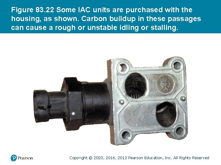
Figure 83. 22 Some IAC units are purchased with the housing, as shown. Carbon buildup in these passages can cause a rough or unstable idling or stalling. Copyright © 2020, 2016, 2012 Pearson Education, Inc. All Rights Reserved
CASE STUDY Copyright © 2020, 2016, 2012 Pearson Education, Inc. All Rights Reserved
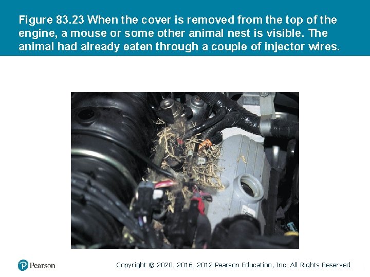
Figure 83. 23 When the cover is removed from the top of the engine, a mouse or some other animal nest is visible. The animal had already eaten through a couple of injector wires. Copyright © 2020, 2016, 2012 Pearson Education, Inc. All Rights Reserved
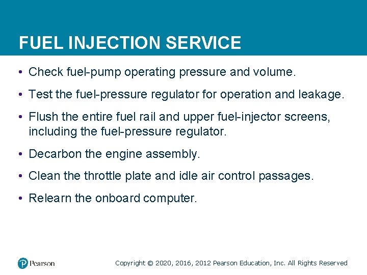
FUEL INJECTION SERVICE • Check fuel-pump operating pressure and volume. • Test the fuel-pressure regulator for operation and leakage. • Flush the entire fuel rail and upper fuel-injector screens, including the fuel-pressure regulator. • Decarbon the engine assembly. • Clean the throttle plate and idle air control passages. • Relearn the onboard computer. Copyright © 2020, 2016, 2012 Pearson Education, Inc. All Rights Reserved
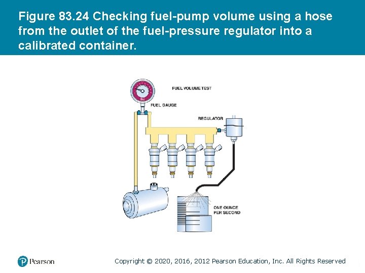
Figure 83. 24 Checking fuel-pump volume using a hose from the outlet of the fuel-pressure regulator into a calibrated container. Copyright © 2020, 2016, 2012 Pearson Education, Inc. All Rights Reserved
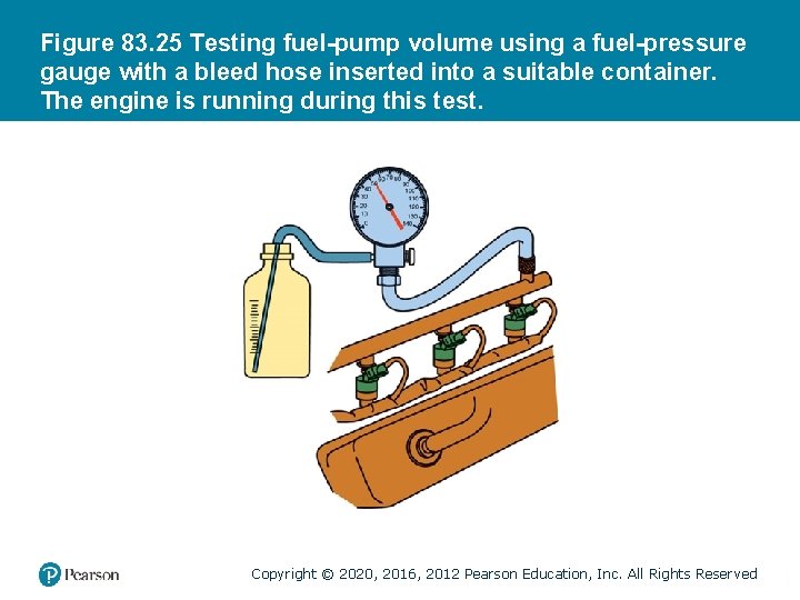
Figure 83. 25 Testing fuel-pump volume using a fuel-pressure gauge with a bleed hose inserted into a suitable container. The engine is running during this test. Copyright © 2020, 2016, 2012 Pearson Education, Inc. All Rights Reserved
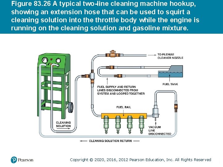
Figure 83. 26 A typical two-line cleaning machine hookup, showing an extension hose that can be used to squirt a cleaning solution into the throttle body while the engine is running on the cleaning solution and gasoline mixture. Copyright © 2020, 2016, 2012 Pearson Education, Inc. All Rights Reserved
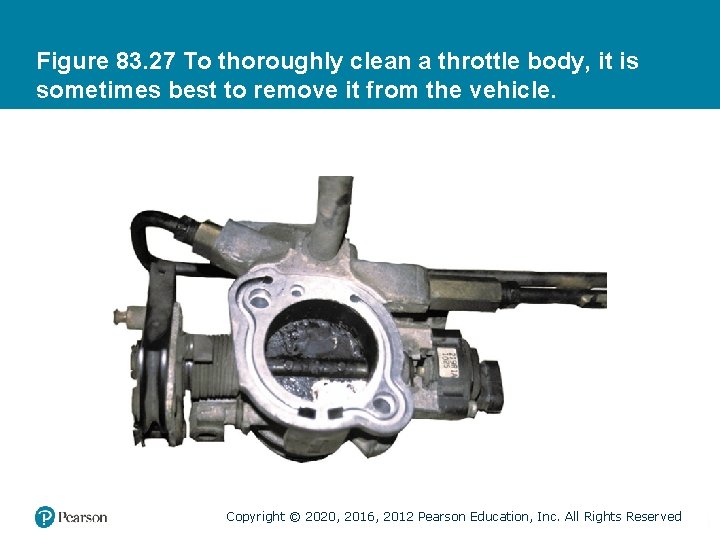
Figure 83. 27 To thoroughly clean a throttle body, it is sometimes best to remove it from the vehicle. Copyright © 2020, 2016, 2012 Pearson Education, Inc. All Rights Reserved
QUESTION 3: ? Why do injectors need to be serviced? Copyright © 2020, 2016, 2012 Pearson Education, Inc. All Rights Reserved
ANSWER 3: To remove the accumulation of carbon and other additives that are restricting the fuel flow. Copyright © 2020, 2016, 2012 Pearson Education, Inc. All Rights Reserved
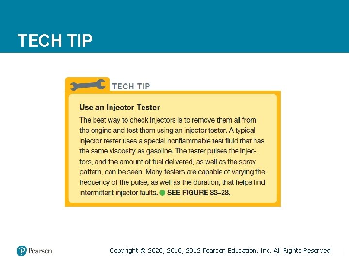
TECH TIP Copyright © 2020, 2016, 2012 Pearson Education, Inc. All Rights Reserved
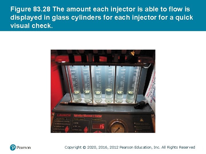
Figure 83. 28 The amount each injector is able to flow is displayed in glass cylinders for each injector for a quick visual check. Copyright © 2020, 2016, 2012 Pearson Education, Inc. All Rights Reserved
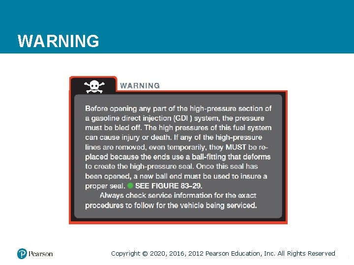
WARNING Copyright © 2020, 2016, 2012 Pearson Education, Inc. All Rights Reserved
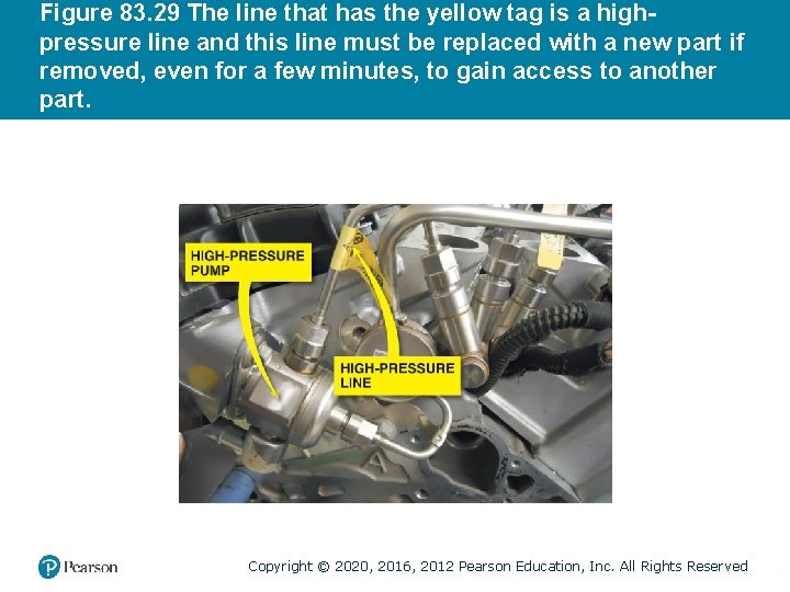
Figure 83. 29 The line that has the yellow tag is a highpressure line and this line must be replaced with a new part if removed, even for a few minutes, to gain access to another part. Copyright © 2020, 2016, 2012 Pearson Education, Inc. All Rights Reserved
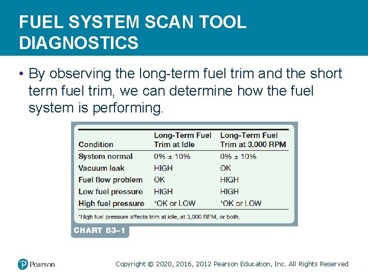
FUEL SYSTEM SCAN TOOL DIAGNOSTICS • By observing the long-term fuel trim and the short term fuel trim, we can determine how the fuel system is performing. Copyright © 2020, 2016, 2012 Pearson Education, Inc. All Rights Reserved
FUEL-PUMP RELAY CIRCUIT DIAGNOSIS Copyright © 2020, 2016, 2012 Pearson Education, Inc. All Rights Reserved
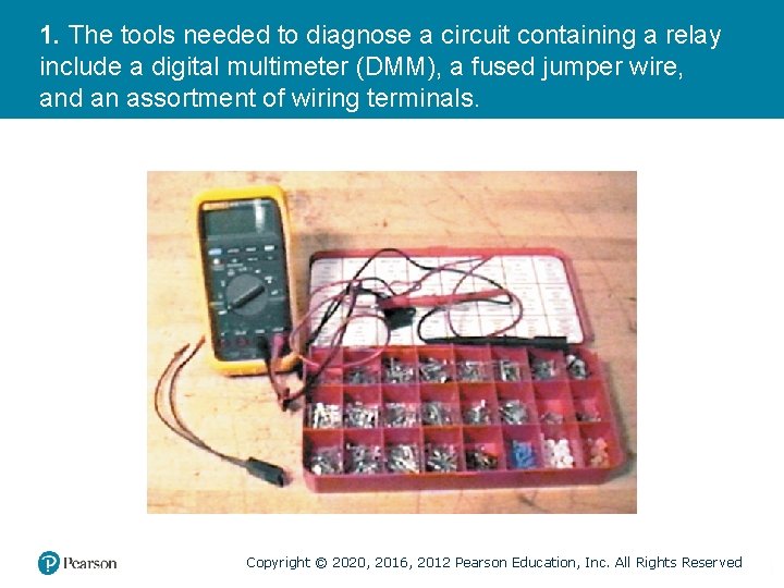
1. The tools needed to diagnose a circuit containing a relay include a digital multimeter (DMM), a fused jumper wire, and an assortment of wiring terminals. Copyright © 2020, 2016, 2012 Pearson Education, Inc. All Rights Reserved
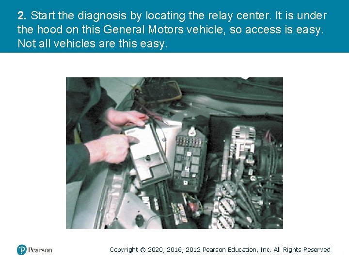
2. Start the diagnosis by locating the relay center. It is under the hood on this General Motors vehicle, so access is easy. Not all vehicles are this easy. Copyright © 2020, 2016, 2012 Pearson Education, Inc. All Rights Reserved
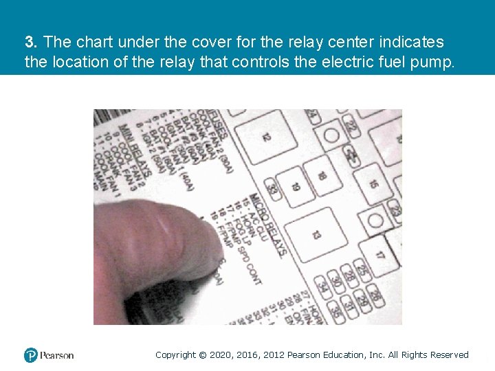
3. The chart under the cover for the relay center indicates the location of the relay that controls the electric fuel pump. Copyright © 2020, 2016, 2012 Pearson Education, Inc. All Rights Reserved
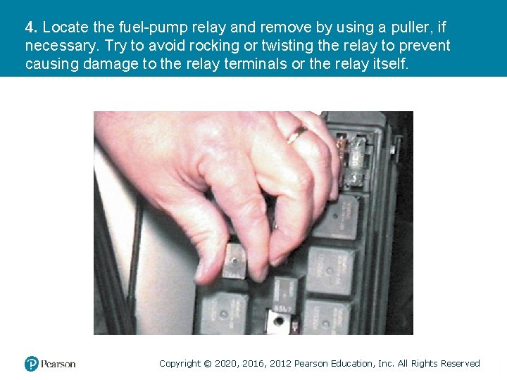
4. Locate the fuel-pump relay and remove by using a puller, if necessary. Try to avoid rocking or twisting the relay to prevent causing damage to the relay terminals or the relay itself. Copyright © 2020, 2016, 2012 Pearson Education, Inc. All Rights Reserved
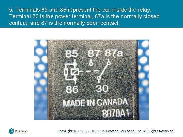
5. Terminals 85 and 86 represent the coil inside the relay. Terminal 30 is the power terminal, 87 a is the normally closed contact, and 87 is the normally open contact. Copyright © 2020, 2016, 2012 Pearson Education, Inc. All Rights Reserved
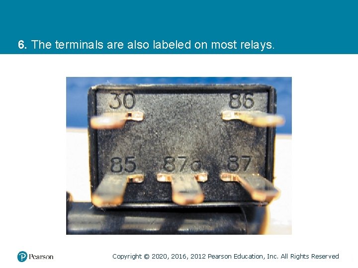
6. The terminals are also labeled on most relays. Copyright © 2020, 2016, 2012 Pearson Education, Inc. All Rights Reserved
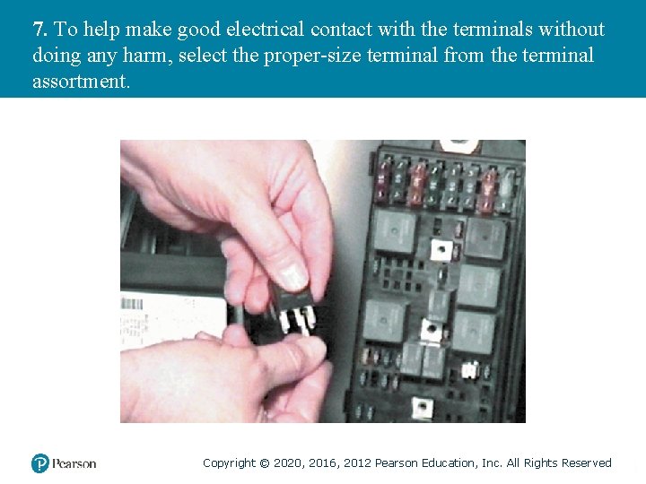
7. To help make good electrical contact with the terminals without doing any harm, select the proper-size terminal from the terminal assortment. Copyright © 2020, 2016, 2012 Pearson Education, Inc. All Rights Reserved
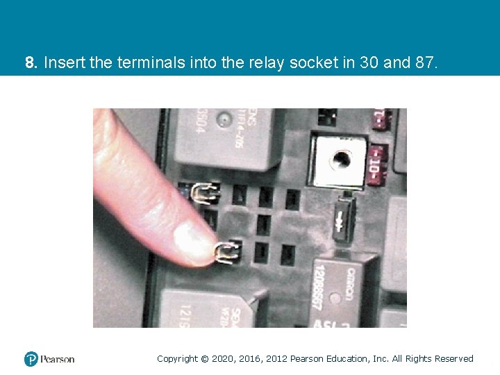
8. Insert the terminals into the relay socket in 30 and 87. Copyright © 2020, 2016, 2012 Pearson Education, Inc. All Rights Reserved
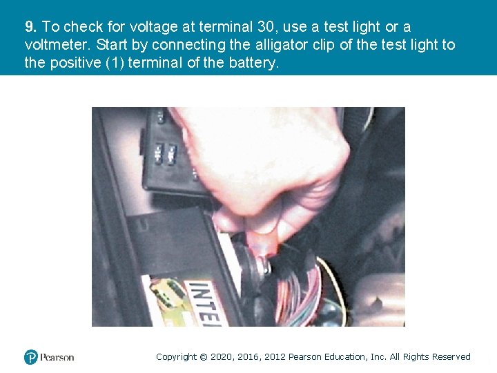
9. To check for voltage at terminal 30, use a test light or a voltmeter. Start by connecting the alligator clip of the test light to the positive (1) terminal of the battery. Copyright © 2020, 2016, 2012 Pearson Education, Inc. All Rights Reserved
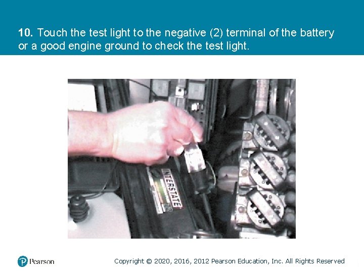
10. Touch the test light to the negative (2) terminal of the battery or a good engine ground to check the test light. Copyright © 2020, 2016, 2012 Pearson Education, Inc. All Rights Reserved
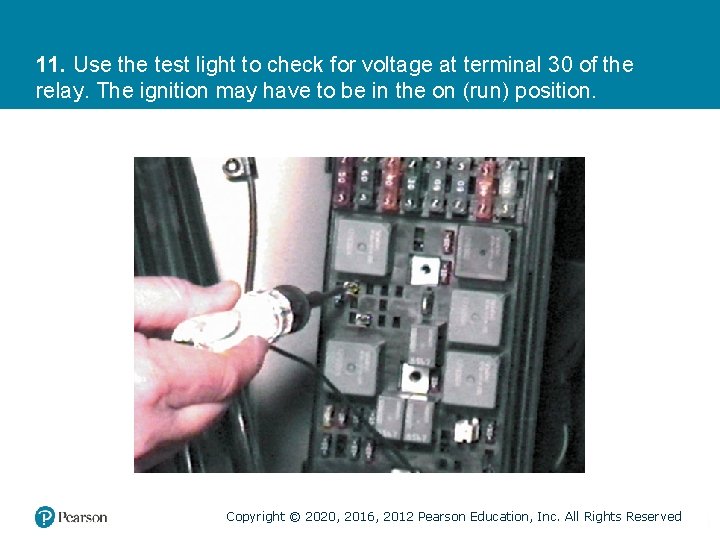
11. Use the test light to check for voltage at terminal 30 of the relay. The ignition may have to be in the on (run) position. Copyright © 2020, 2016, 2012 Pearson Education, Inc. All Rights Reserved
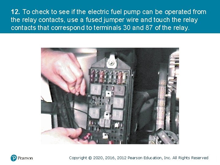
12. To check to see if the electric fuel pump can be operated from the relay contacts, use a fused jumper wire and touch the relay contacts that correspond to terminals 30 and 87 of the relay. Copyright © 2020, 2016, 2012 Pearson Education, Inc. All Rights Reserved
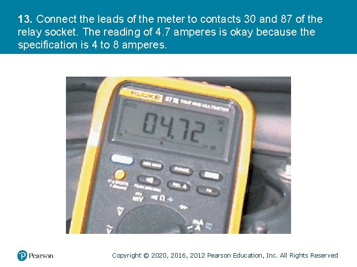
13. Connect the leads of the meter to contacts 30 and 87 of the relay socket. The reading of 4. 7 amperes is okay because the specification is 4 to 8 amperes. Copyright © 2020, 2016, 2012 Pearson Education, Inc. All Rights Reserved
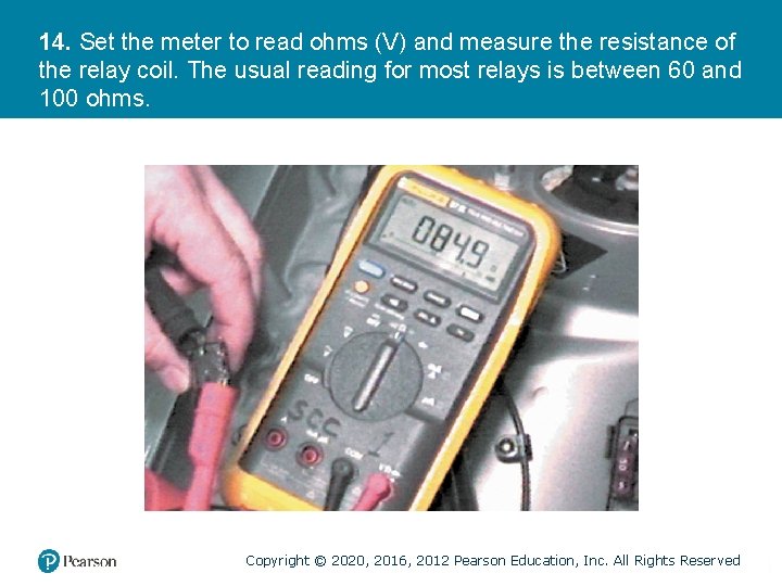
14. Set the meter to read ohms (V) and measure the resistance of the relay coil. The usual reading for most relays is between 60 and 100 ohms. Copyright © 2020, 2016, 2012 Pearson Education, Inc. All Rights Reserved
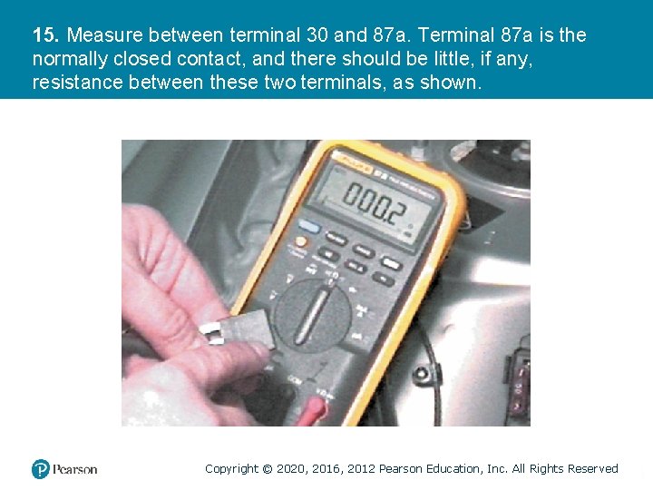
15. Measure between terminal 30 and 87 a. Terminal 87 a is the normally closed contact, and there should be little, if any, resistance between these two terminals, as shown. Copyright © 2020, 2016, 2012 Pearson Education, Inc. All Rights Reserved
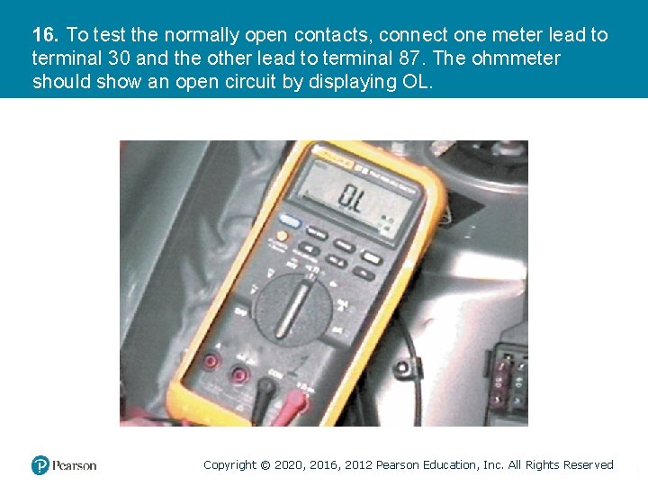
16. To test the normally open contacts, connect one meter lead to terminal 30 and the other lead to terminal 87. The ohmmeter should show an open circuit by displaying OL. Copyright © 2020, 2016, 2012 Pearson Education, Inc. All Rights Reserved
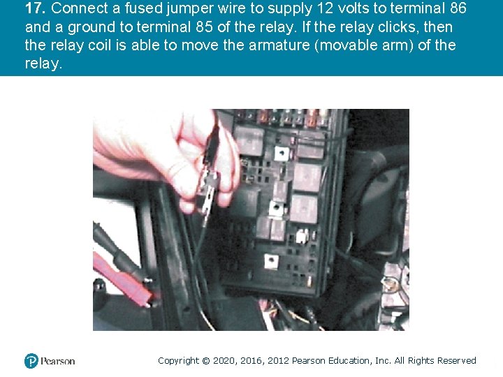
17. Connect a fused jumper wire to supply 12 volts to terminal 86 and a ground to terminal 85 of the relay. If the relay clicks, then the relay coil is able to move the armature (movable arm) of the relay. Copyright © 2020, 2016, 2012 Pearson Education, Inc. All Rights Reserved
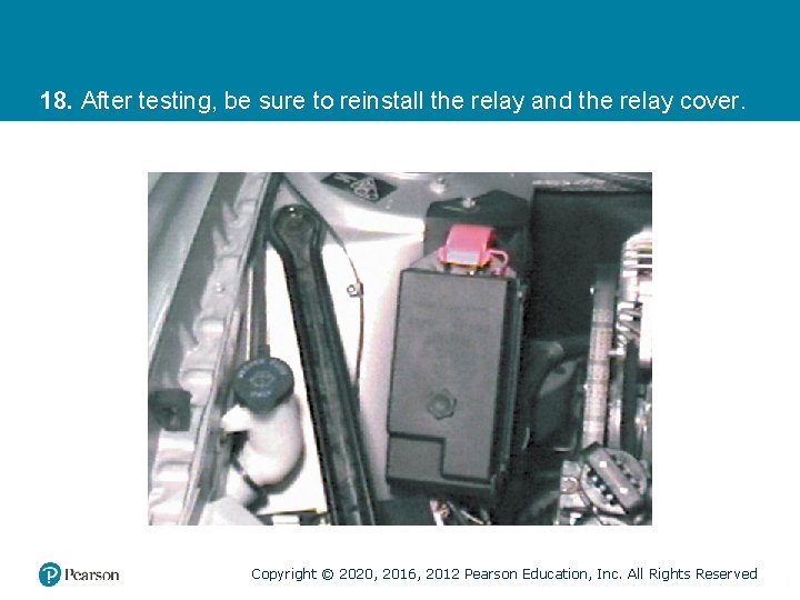
18. After testing, be sure to reinstall the relay and the relay cover. Copyright © 2020, 2016, 2012 Pearson Education, Inc. All Rights Reserved
FUEL INJECTOR CLEANING Copyright © 2020, 2016, 2012 Pearson Education, Inc. All Rights Reserved
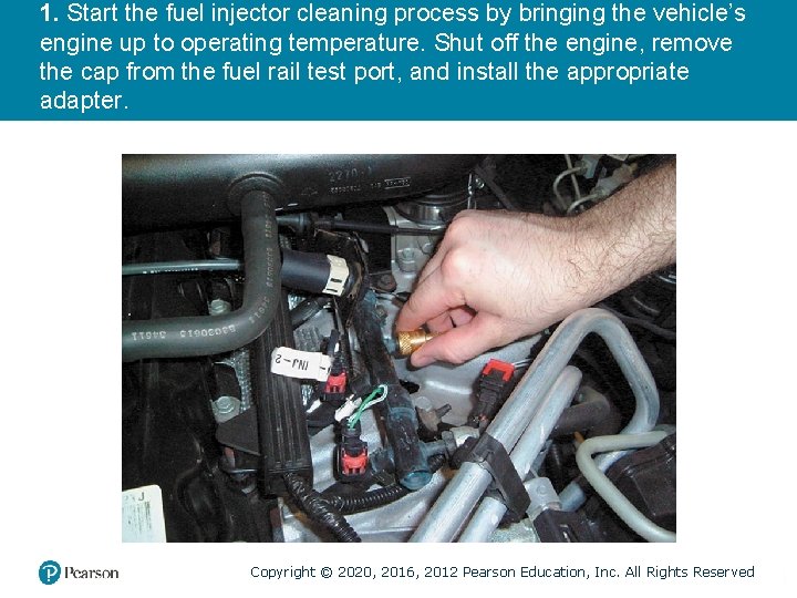
1. Start the fuel injector cleaning process by bringing the vehicle’s engine up to operating temperature. Shut off the engine, remove the cap from the fuel rail test port, and install the appropriate adapter. Copyright © 2020, 2016, 2012 Pearson Education, Inc. All Rights Reserved
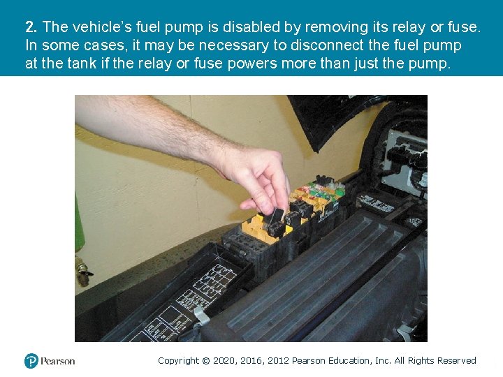
2. The vehicle’s fuel pump is disabled by removing its relay or fuse. In some cases, it may be necessary to disconnect the fuel pump at the tank if the relay or fuse powers more than just the pump. Copyright © 2020, 2016, 2012 Pearson Education, Inc. All Rights Reserved
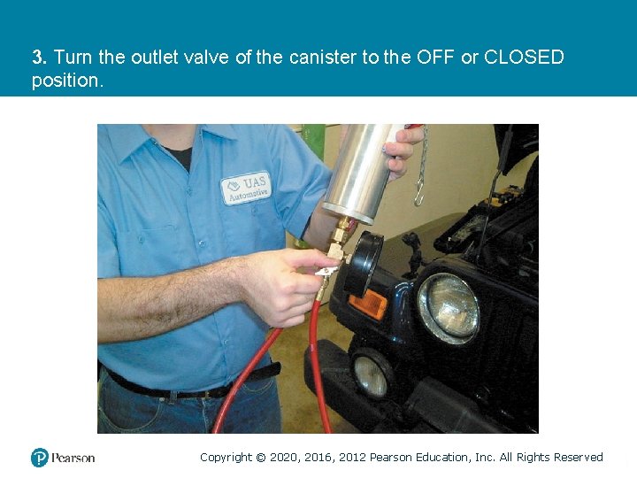
3. Turn the outlet valve of the canister to the OFF or CLOSED position. Copyright © 2020, 2016, 2012 Pearson Education, Inc. All Rights Reserved
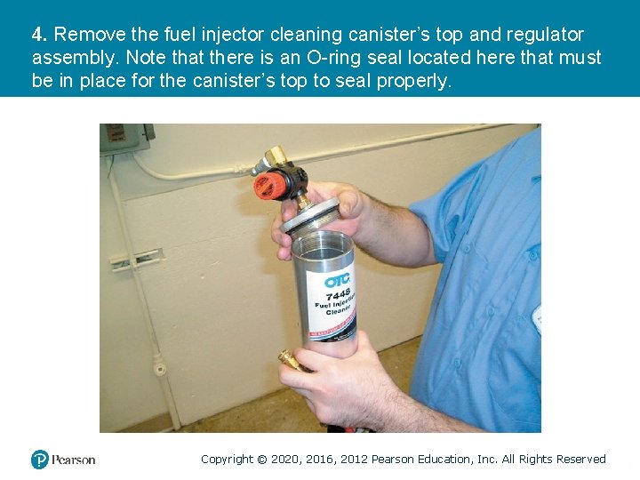
4. Remove the fuel injector cleaning canister’s top and regulator assembly. Note that there is an O-ring seal located here that must be in place for the canister’s top to seal properly. Copyright © 2020, 2016, 2012 Pearson Education, Inc. All Rights Reserved
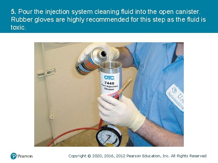
5. Pour the injection system cleaning fluid into the open canister. Rubber gloves are highly recommended for this step as the fluid is toxic. Copyright © 2020, 2016, 2012 Pearson Education, Inc. All Rights Reserved
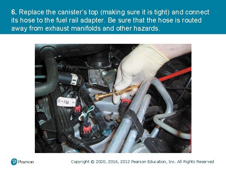
6. Replace the canister’s top (making sure it is tight) and connect its hose to the fuel rail adapter. Be sure that the hose is routed away from exhaust manifolds and other hazards. Copyright © 2020, 2016, 2012 Pearson Education, Inc. All Rights Reserved
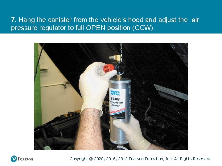
7. Hang the canister from the vehicle’s hood and adjust the air pressure regulator to full OPEN position (CCW). Copyright © 2020, 2016, 2012 Pearson Education, Inc. All Rights Reserved
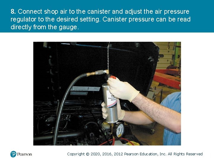
8. Connect shop air to the canister and adjust the air pressure regulator to the desired setting. Canister pressure can be read directly from the gauge. Copyright © 2020, 2016, 2012 Pearson Education, Inc. All Rights Reserved
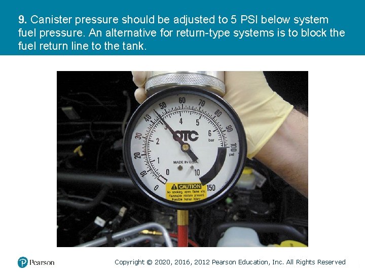
9. Canister pressure should be adjusted to 5 PSI below system fuel pressure. An alternative for return-type systems is to block the fuel return line to the tank. Copyright © 2020, 2016, 2012 Pearson Education, Inc. All Rights Reserved
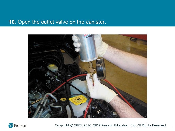
10. Open the outlet valve on the canister. Copyright © 2020, 2016, 2012 Pearson Education, Inc. All Rights Reserved
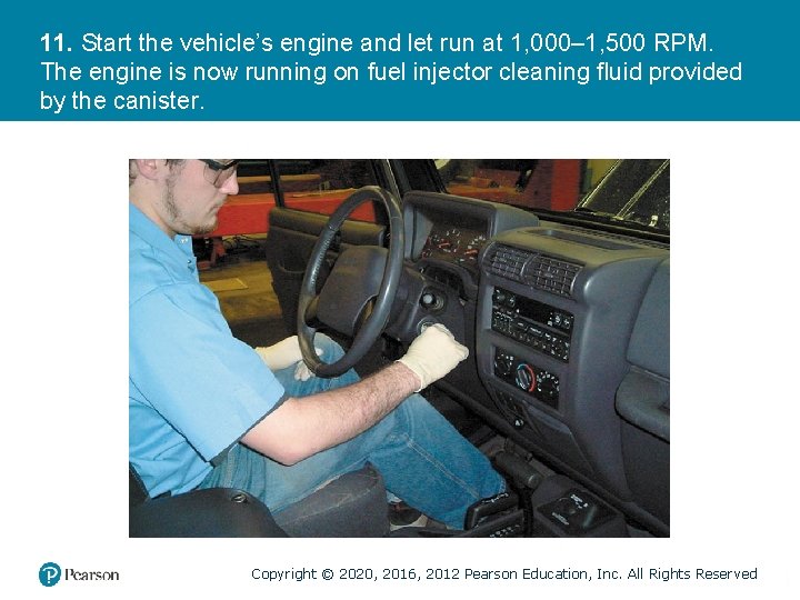
11. Start the vehicle’s engine and let run at 1, 000– 1, 500 RPM. The engine is now running on fuel injector cleaning fluid provided by the canister. Copyright © 2020, 2016, 2012 Pearson Education, Inc. All Rights Reserved
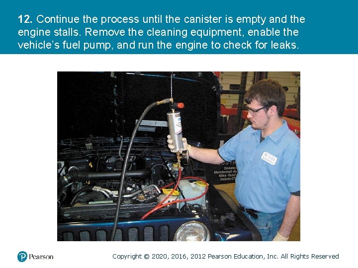
12. Continue the process until the canister is empty and the engine stalls. Remove the cleaning equipment, enable the vehicle’s fuel pump, and run the engine to check for leaks. Copyright © 2020, 2016, 2012 Pearson Education, Inc. All Rights Reserved
Copyright © 2020, 2016, 2012 Pearson Education, Inc. All Rights Reserved