
Automotive Technology Principles Sixth Edition Diagnosis and Service
- Slides: 113
Automotive Technology Principles, Sixth Edition Diagnosis, and Service Chapter 117 Front Suspension and Service Copyright © 2018, 2015, 2011 Pearson Education, Inc. All Rights Reserved Copyright © 2020, 2016, 2012 Pearson Education, Inc. All Rights Reserved
LEARNING OBJECTIVES (1 of 2) 117. 1 Describe different front suspension types. 117. 2 Diagnose short/long-arm (SLA) suspension systems and discuss strut suspension. 117. 3 Explain how to perform a road test, a dry park test, and a visual inspection. 117. 4 Discuss the diagnosis of ball joints and kingpins. 117. 5 Discuss the diagnosis of shock absorbers and struts. Copyright © 2020, 2016, 2012 Pearson Education, Inc. All Rights Reserved
LEARNING OBJECTIVES (2 of 2) 117. 6 Describe how to replace Mac. Pherson struts. 117. 7 Explain the diagnosis of stabilizer bar links and bushings. 117. 8 Discuss the diagnosis of strut rod bushings, front coil springs, steering knuckles, torsion bars, and control arm bushings. 117. 9 This chapter will help prepare for ASE Suspension and Steering (A 4) certification content area “B” (Suspension System Diagnosis and Repair). Copyright © 2020, 2016, 2012 Pearson Education, Inc. All Rights Reserved
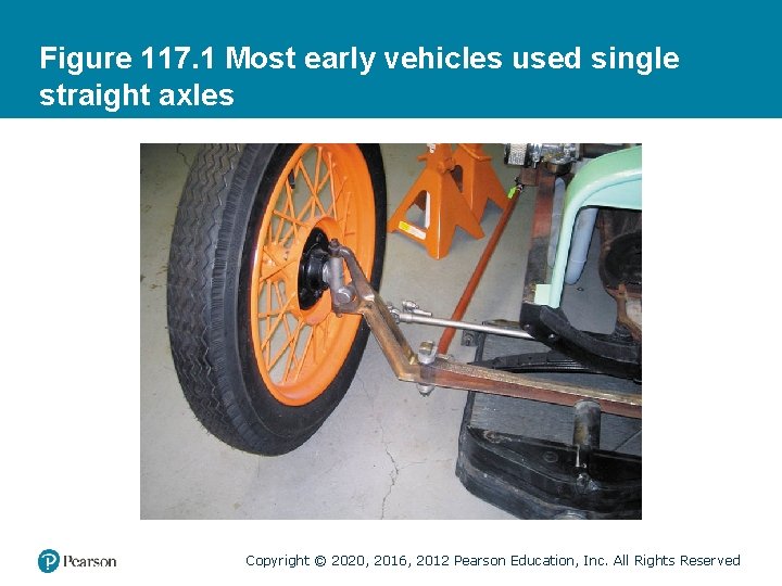
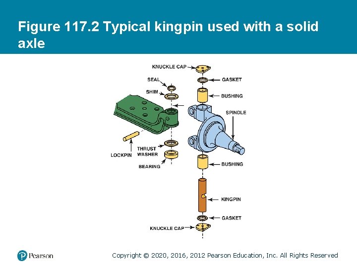
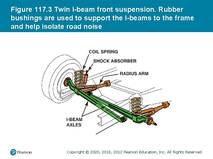
FRONT SUSPENSION TYPES • Solid Axles – Early cars and trucks used a solid (or straight) front axle to support the front wheels. • Kingpins – At the end of solid axle, they allow the front wheels to rotate for steering. • Twin-I Beam – Strong steel twin beams that cross provide independent front suspension operation with the strength of a solid front axle. Copyright © 2020, 2016, 2012 Pearson Education, Inc. All Rights Reserved
Figure 117. 1 Most early vehicles used single straight axles Copyright © 2020, 2016, 2012 Pearson Education, Inc. All Rights Reserved
Figure 117. 2 Typical kingpin used with a solid axle Copyright © 2020, 2016, 2012 Pearson Education, Inc. All Rights Reserved
Figure 117. 3 Twin I-beam front suspension. Rubber bushings are used to support the I-beams to the frame and help isolate road noise Copyright © 2020, 2016, 2012 Pearson Education, Inc. All Rights Reserved
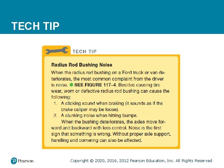
TECH TIP Copyright © 2020, 2016, 2012 Pearson Education, Inc. All Rights Reserved
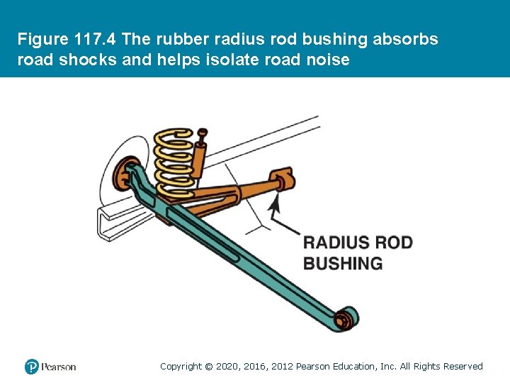
Figure 117. 4 The rubber radius rod bushing absorbs road shocks and helps isolate road noise Copyright © 2020, 2016, 2012 Pearson Education, Inc. All Rights Reserved
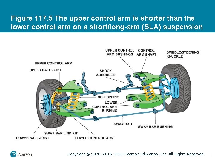
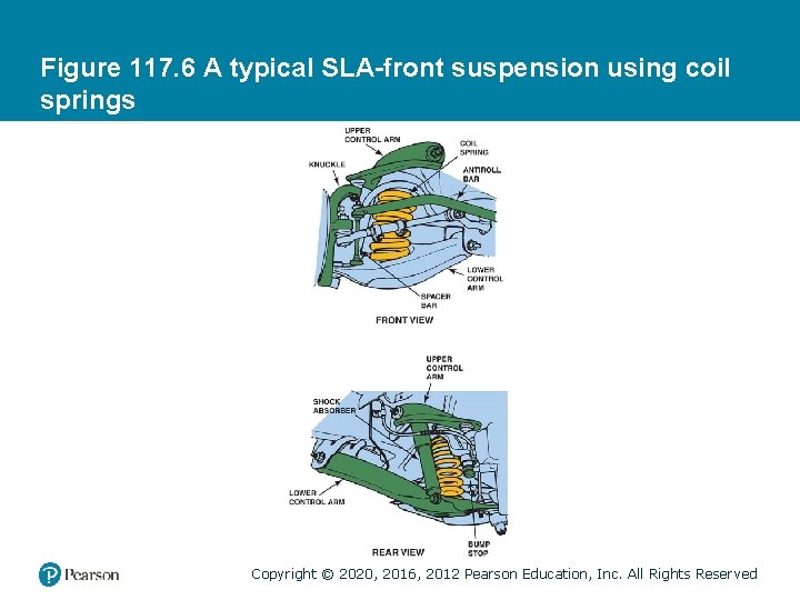
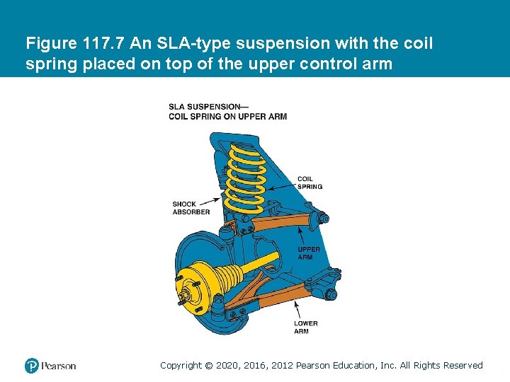
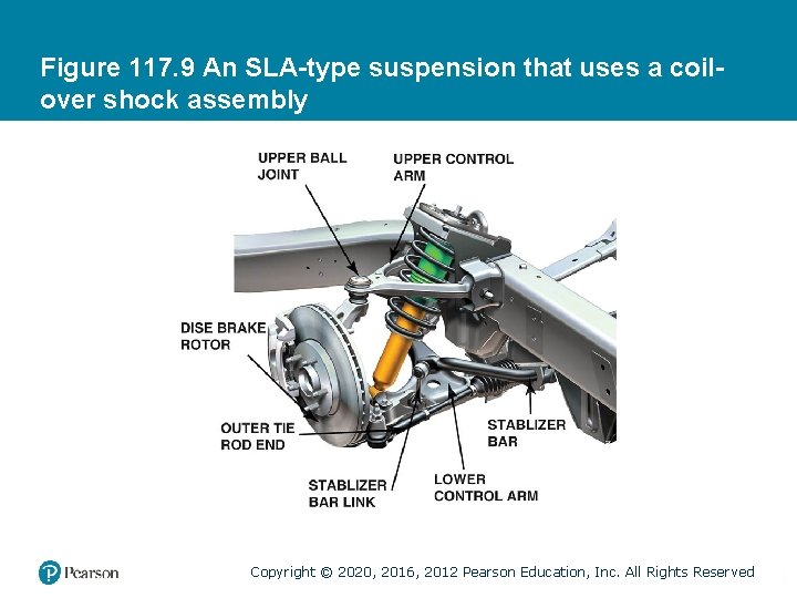
SHORT/LONG-ARM SUSPENSIONS (1 OF 2) • Terminology – The short/long-arm suspension uses a short upper control arm and a longer lower control arm and is usually referred to as the SLA-type suspension. • Strut Rods – A strut rod, also called a reaction rod, provides support to the axle during braking and acceleration forces. Copyright © 2020, 2016, 2012 Pearson Education, Inc. All Rights Reserved
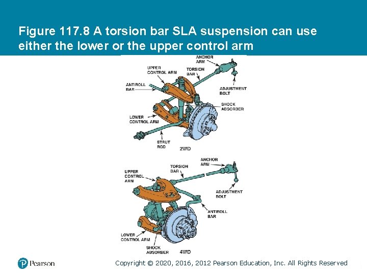
SHORT/LONG-ARM SUSPENSIONS (2 OF 2) • Coil Spring Front Suspensions – Locating the coil spring on the lower control arm is the most common SLA-type suspension configuration. • Torsion Bar Front Suspensions – Short/long-arm suspensions use longitudinal torsion bars, especially in trucks. Copyright © 2020, 2016, 2012 Pearson Education, Inc. All Rights Reserved
Figure 117. 5 The upper control arm is shorter than the lower control arm on a short/long-arm (SLA) suspension Copyright © 2020, 2016, 2012 Pearson Education, Inc. All Rights Reserved
Figure 117. 6 A typical SLA-front suspension using coil springs Copyright © 2020, 2016, 2012 Pearson Education, Inc. All Rights Reserved
Figure 117. 7 An SLA-type suspension with the coil spring placed on top of the upper control arm Copyright © 2020, 2016, 2012 Pearson Education, Inc. All Rights Reserved
Figure 117. 8 A torsion bar SLA suspension can use either the lower or the upper control arm Copyright © 2020, 2016, 2012 Pearson Education, Inc. All Rights Reserved
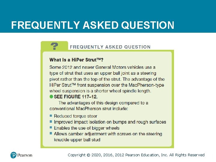
FREQUENTLY ASKED QUESTION Copyright © 2020, 2016, 2012 Pearson Education, Inc. All Rights Reserved
Figure 117. 9 An SLA-type suspension that uses a coilover shock assembly Copyright © 2020, 2016, 2012 Pearson Education, Inc. All Rights Reserved
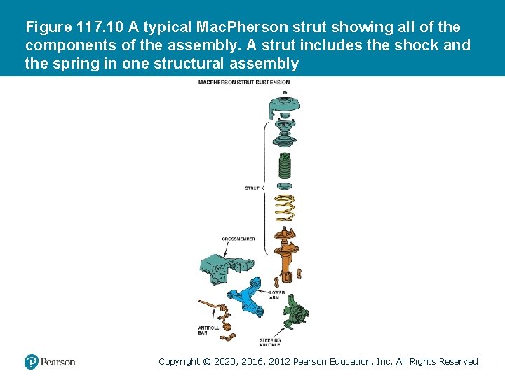
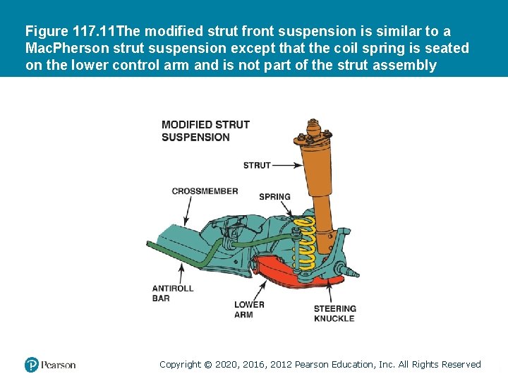
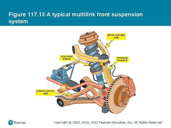
STRUT SUSPENSION • Parts and Operation – A Mac. Pherson strut includes the suspension spring that transfers the weight of the body to the wheel. – A modified strut does not include a spring as part of the assembly. – A multilink front suspension uses two control arms as well as a structural strut assembly. Copyright © 2020, 2016, 2012 Pearson Education, Inc. All Rights Reserved
Figure 117. 10 A typical Mac. Pherson strut showing all of the components of the assembly. A strut includes the shock and the spring in one structural assembly Copyright © 2020, 2016, 2012 Pearson Education, Inc. All Rights Reserved
Figure 117. 11 The modified strut front suspension is similar to a Mac. Pherson strut suspension except that the coil spring is seated on the lower control arm and is not part of the strut assembly Copyright © 2020, 2016, 2012 Pearson Education, Inc. All Rights Reserved
FREQUENTLY ASKED QUESTION Copyright © 2020, 2016, 2012 Pearson Education, Inc. All Rights Reserved
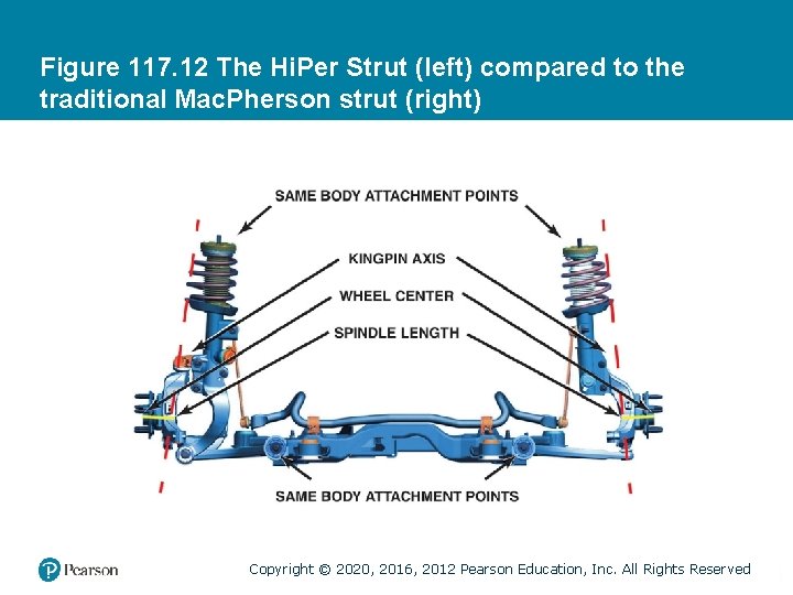
Figure 117. 12 The Hi. Per Strut (left) compared to the traditional Mac. Pherson strut (right) Copyright © 2020, 2016, 2012 Pearson Education, Inc. All Rights Reserved
Figure 117. 13 A typical multilink front suspension system Copyright © 2020, 2016, 2012 Pearson Education, Inc. All Rights Reserved
SERVICING THE SUSPENSION SYSTEM • When the driver notices that the vehicle is not riding or handling as it did, he or she brings it to a technician to repair or align the vehicle. • The smart technician should always road test any vehicle before and after servicing. Copyright © 2020, 2016, 2012 Pearson Education, Inc. All Rights Reserved
ROAD TEST DIAGNOSIS (1 OF 2) • While driving, try to determine when and where the noise or problem occurs, such as the following: – In cold or warm weather – With cold or warm engine/vehicle – While turning, left only, right only Copyright © 2020, 2016, 2012 Pearson Education, Inc. All Rights Reserved
ROAD TEST DIAGNOSIS (2 OF 2) • A proper road test for any suspension system problem should include the following: – – Drive beside parked vehicles. Drive into driveways. Drive in reverse while turning. Drive over a bumpy road. Copyright © 2020, 2016, 2012 Pearson Education, Inc. All Rights Reserved
DRY PARK TEST (SUSPENSION) • The dry park test is performed by having an assistant move the steering wheel side to side while feeling and observing for any free-play in the steering or suspension. • In this suspension analysis using the dry park test, the technician should observe the following for any noticeable play or unusual noise: – Front wheel bearings. – Control arm bushing wear or movement. – Ball joint movement. Copyright © 2020, 2016, 2012 Pearson Education, Inc. All Rights Reserved
VISUAL INSPECTION • A thorough visual inspection should include checking all of the following: – – – – Shock absorbers and struts. Springs Stabilizer bar links and bushings Upper and lower shock absorber mounting points Bump stops Body-to-chassis mounts Engine and transmission (transaxle) mounts Suspension arm bushings. Copyright © 2020, 2016, 2012 Pearson Education, Inc. All Rights Reserved
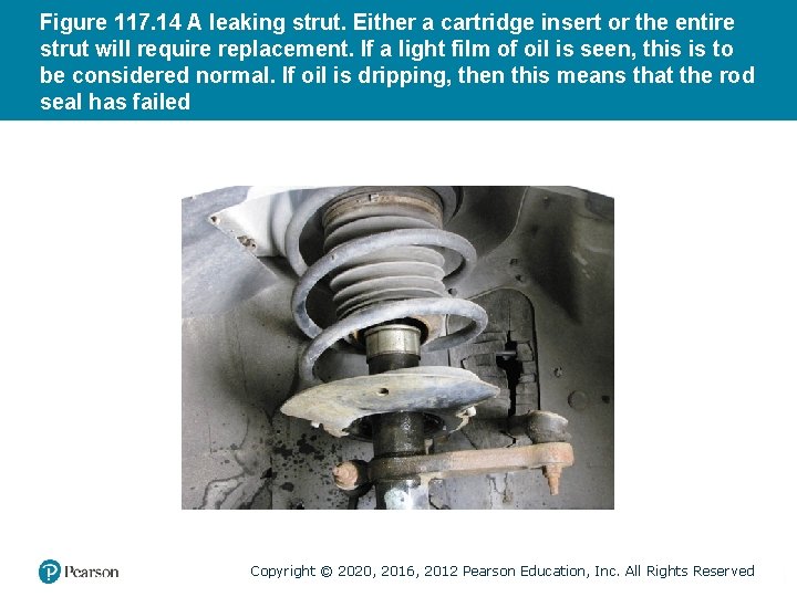
Figure 117. 14 A leaking strut. Either a cartridge insert or the entire strut will require replacement. If a light film of oil is seen, this is to be considered normal. If oil is dripping, then this means that the rod seal has failed Copyright © 2020, 2016, 2012 Pearson Education, Inc. All Rights Reserved
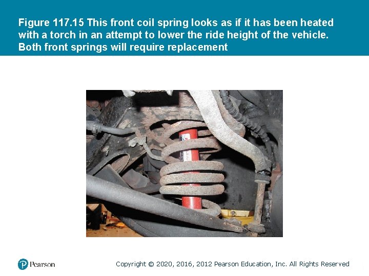
Figure 117. 15 This front coil spring looks as if it has been heated with a torch in an attempt to lower the ride height of the vehicle. Both front springs will require replacement Copyright © 2020, 2016, 2012 Pearson Education, Inc. All Rights Reserved
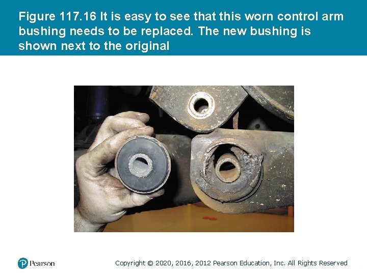
Figure 117. 16 It is easy to see that this worn control arm bushing needs to be replaced. The new bushing is shown next to the original Copyright © 2020, 2016, 2012 Pearson Education, Inc. All Rights Reserved
QUESTION 1: ? What is the purpose of the dry park test? Copyright © 2020, 2016, 2012 Pearson Education, Inc. All Rights Reserved
ANSWER 1: To look for play in components as the steering wheel is turned side-toside. Copyright © 2020, 2016, 2012 Pearson Education, Inc. All Rights Reserved
BALL JOINTS (1 OF 3) • Diagnosis and Inspection • Defective or worn ball joints can cause looseness in the suspension and the following common driver complaints: – Loud popping or squeaking whenever driving over curbs, such as into a driveway – Shimmy-type vibration felt in the steering wheel – Vehicle wander or a tendency not to track straight – Excessive freeplay in the steering wheel Copyright © 2020, 2016, 2012 Pearson Education, Inc. All Rights Reserved
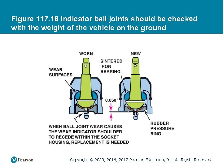
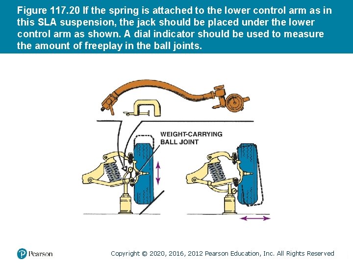
BALL JOINTS (2 OF 3) • A ball joint inspection should also be done when an alignment is performed or as part of any other comprehensive vehicle inspection. – Always check wear-indicator-type ball joints with the wheels of the vehicle on the ground. – To perform a proper non-indicator-type ball joint inspection, the force of the vehicle’s springs must be unloaded from the ball joint. • Follower ball joints (friction ball joints) should also be inspected while testing load-carrying ball joints. Copyright © 2020, 2016, 2012 Pearson Education, Inc. All Rights Reserved
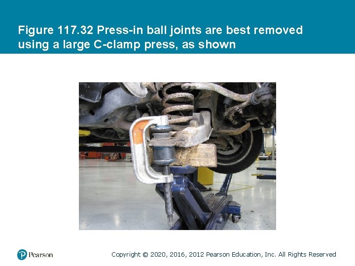
BALL JOINTS (3 OF 3) • Ball Joint Removal – The removal procedures vary with the style of ball joint and the design of the suspension system. – The preferred method to separate ball joints in a puller. – Use caution so as to not damage any attaching components. – Follow the manufacturers recommended procedures. • Many vehicles are equipped with non-replaceable ball joints, and the entire control arm must be replaced if the ball joint is worn or defective. Copyright © 2020, 2016, 2012 Pearson Education, Inc. All Rights Reserved
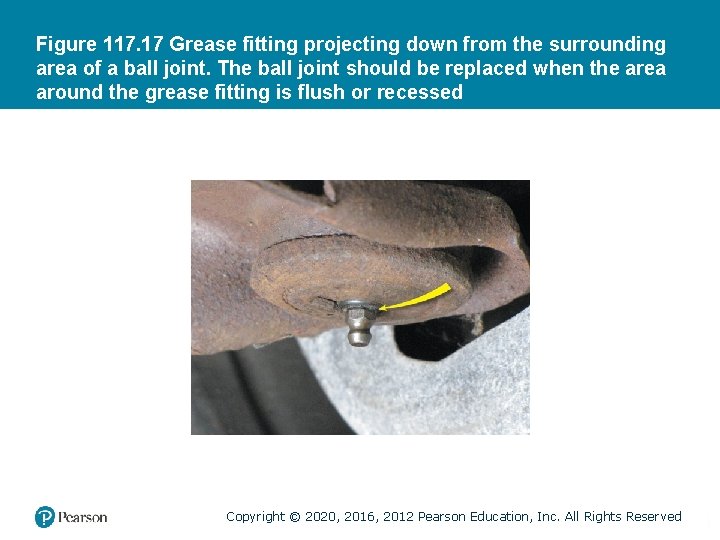
Figure 117. 17 Grease fitting projecting down from the surrounding area of a ball joint. The ball joint should be replaced when the area around the grease fitting is flush or recessed Copyright © 2020, 2016, 2012 Pearson Education, Inc. All Rights Reserved
Figure 117. 18 Indicator ball joints should be checked with the weight of the vehicle on the ground Copyright © 2020, 2016, 2012 Pearson Education, Inc. All Rights Reserved
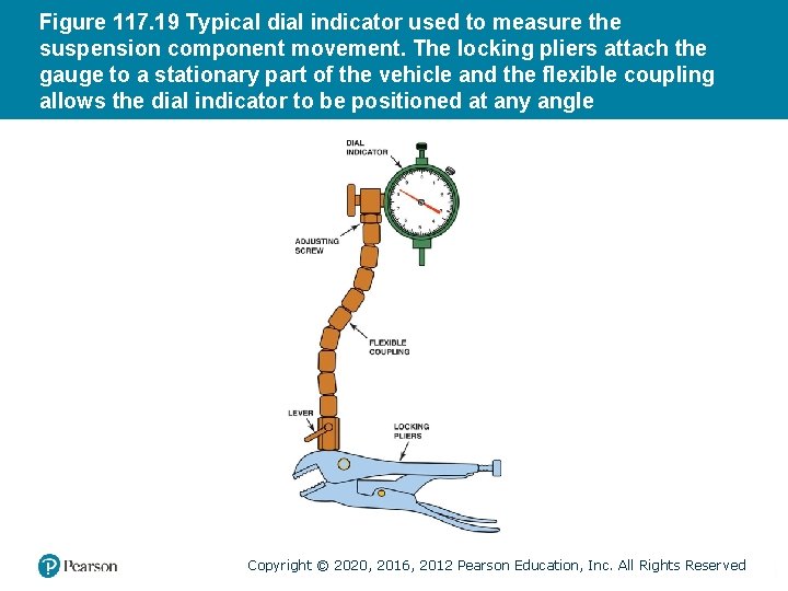
Figure 117. 19 Typical dial indicator used to measure the suspension component movement. The locking pliers attach the gauge to a stationary part of the vehicle and the flexible coupling allows the dial indicator to be positioned at any angle Copyright © 2020, 2016, 2012 Pearson Education, Inc. All Rights Reserved
Figure 117. 20 If the spring is attached to the lower control arm as in this SLA suspension, the jack should be placed under the lower control arm as shown. A dial indicator should be used to measure the amount of freeplay in the ball joints. Copyright © 2020, 2016, 2012 Pearson Education, Inc. All Rights Reserved
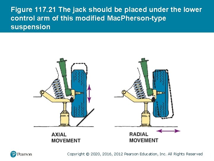
Figure 117. 21 The jack should be placed under the lower control arm of this modified Mac. Pherson-type suspension Copyright © 2020, 2016, 2012 Pearson Education, Inc. All Rights Reserved
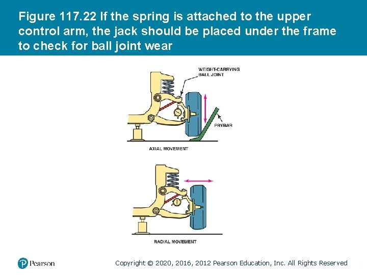
Figure 117. 22 If the spring is attached to the upper control arm, the jack should be placed under the frame to check for ball joint wear Copyright © 2020, 2016, 2012 Pearson Education, Inc. All Rights Reserved
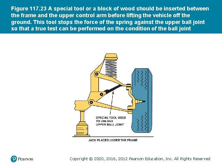
Figure 117. 23 A special tool or a block of wood should be inserted between the frame and the upper control arm before lifting the vehicle off the ground. This tool stops the force of the spring against the upper ball joint so that a true test can be performed on the condition of the ball joint Copyright © 2020, 2016, 2012 Pearson Education, Inc. All Rights Reserved
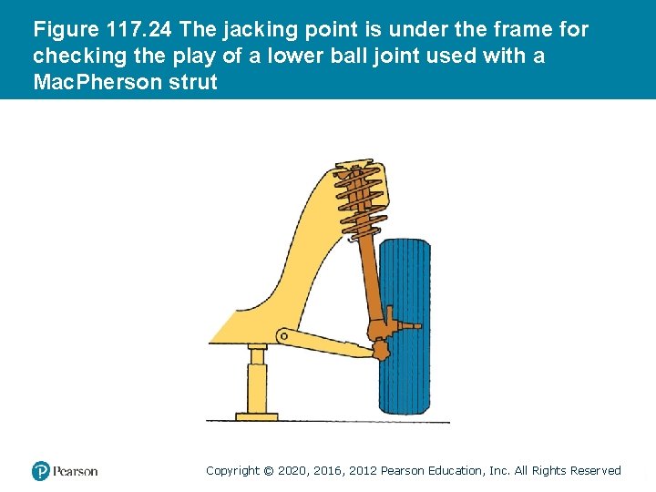
Figure 117. 24 The jacking point is under the frame for checking the play of a lower ball joint used with a Mac. Pherson strut Copyright © 2020, 2016, 2012 Pearson Education, Inc. All Rights Reserved
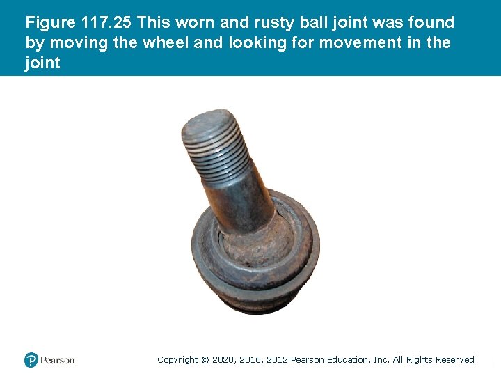
Figure 117. 25 This worn and rusty ball joint was found by moving the wheel and looking for movement in the joint Copyright © 2020, 2016, 2012 Pearson Education, Inc. All Rights Reserved
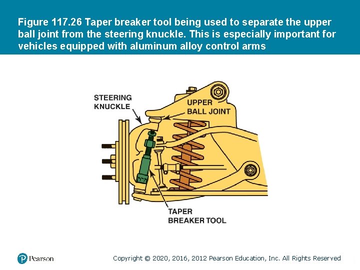
Figure 117. 26 Taper breaker tool being used to separate the upper ball joint from the steering knuckle. This is especially important for vehicles equipped with aluminum alloy control arms Copyright © 2020, 2016, 2012 Pearson Education, Inc. All Rights Reserved
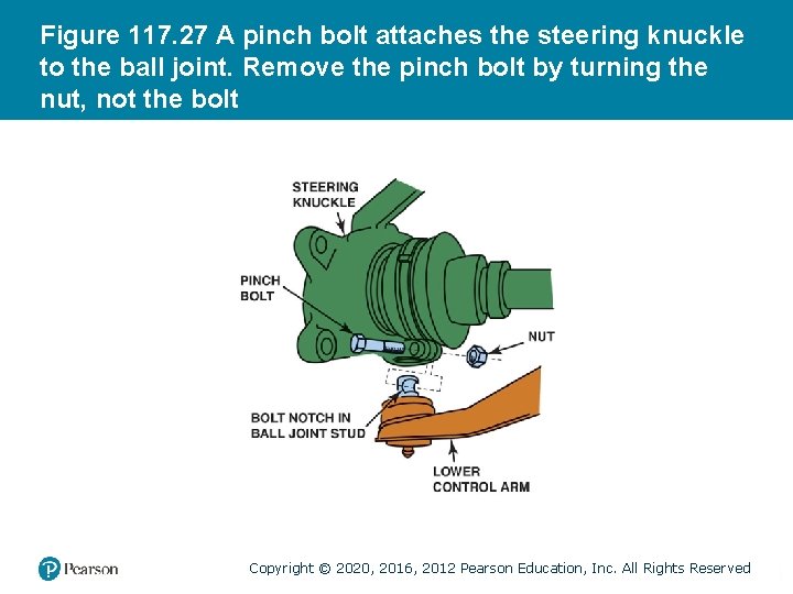
Figure 117. 27 A pinch bolt attaches the steering knuckle to the ball joint. Remove the pinch bolt by turning the nut, not the bolt Copyright © 2020, 2016, 2012 Pearson Education, Inc. All Rights Reserved
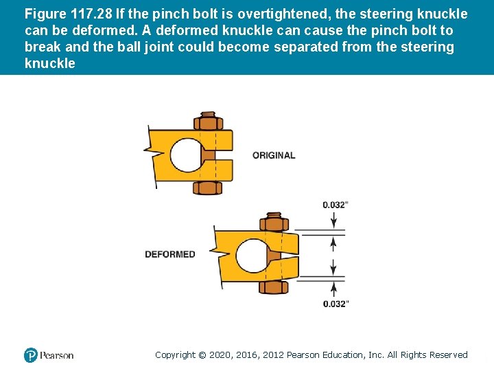
Figure 117. 28 If the pinch bolt is overtightened, the steering knuckle can be deformed. A deformed knuckle can cause the pinch bolt to break and the ball joint could become separated from the steering knuckle Copyright © 2020, 2016, 2012 Pearson Education, Inc. All Rights Reserved
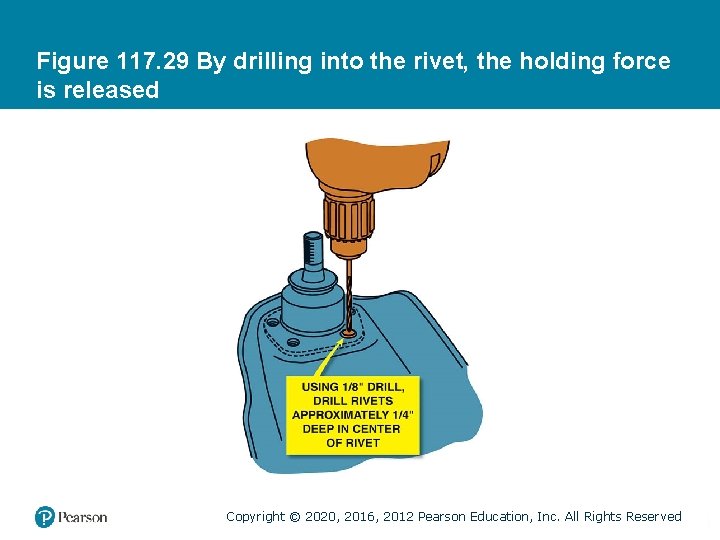
Figure 117. 29 By drilling into the rivet, the holding force is released Copyright © 2020, 2016, 2012 Pearson Education, Inc. All Rights Reserved
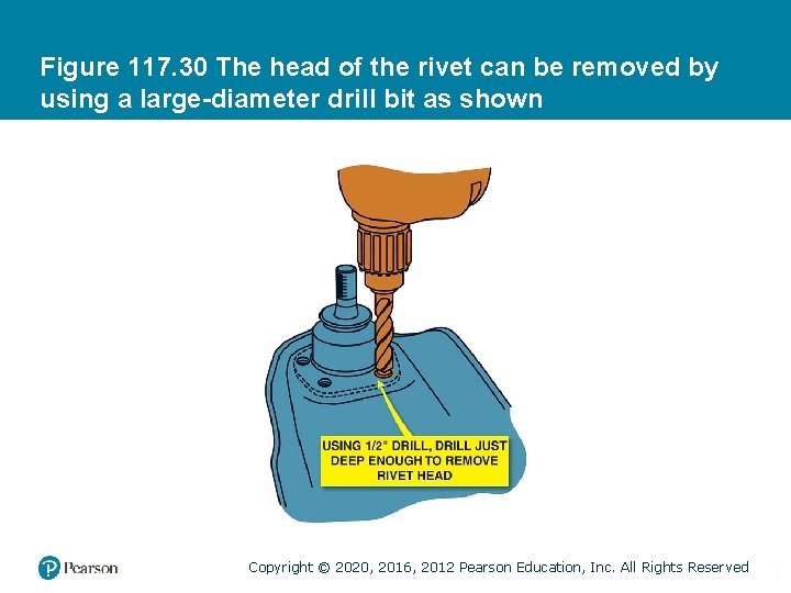
Figure 117. 30 The head of the rivet can be removed by using a large-diameter drill bit as shown Copyright © 2020, 2016, 2012 Pearson Education, Inc. All Rights Reserved
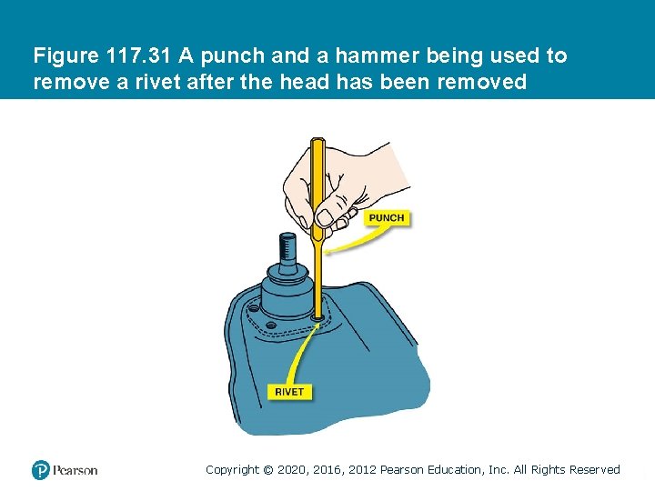
Figure 117. 31 A punch and a hammer being used to remove a rivet after the head has been removed Copyright © 2020, 2016, 2012 Pearson Education, Inc. All Rights Reserved
Figure 117. 32 Press-in ball joints are best removed using a large C-clamp press, as shown Copyright © 2020, 2016, 2012 Pearson Education, Inc. All Rights Reserved
QUESTION 2: ? What are the symptoms of a defective ball joint? Copyright © 2020, 2016, 2012 Pearson Education, Inc. All Rights Reserved
ANSWER 2: Noise, shimmy, wander, and excessive freeplay in the steering. Copyright © 2020, 2016, 2012 Pearson Education, Inc. All Rights Reserved
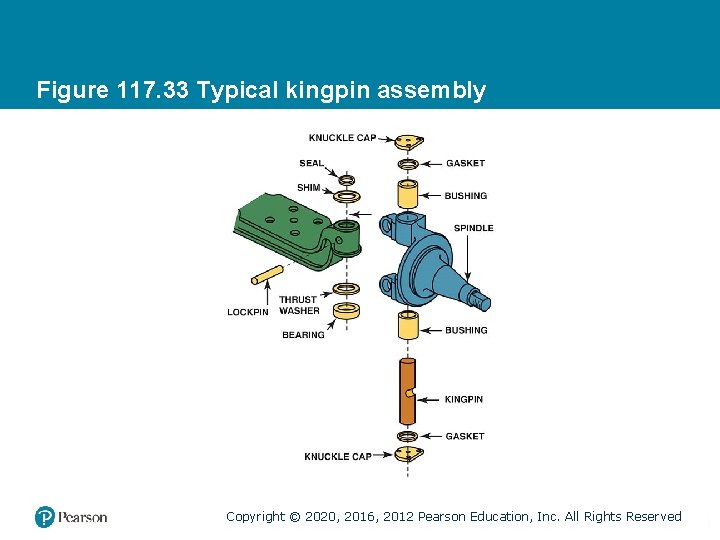
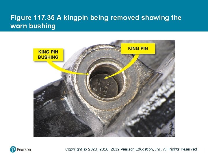
KINGPIN DIAGNOSIS AND SERVICE (1 OF 2) • Kingpins are designed to rotate inside kingpin bushings with a clearance between them of approximately 0. 001 to 0. 003 inch (0. 025 to 0. 075 mm). • Looseness in the kingpin causes looseness in the wheels and steering. • Kingpins can also gall or seize due to lack of lubrication, resulting in very hard steering. Copyright © 2020, 2016, 2012 Pearson Education, Inc. All Rights Reserved
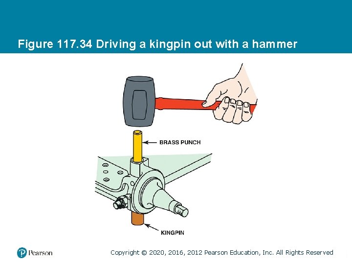
KINGPIN DIAGNOSIS AND SERVICE (2 OF 2) • To remove a typical kingpin, follow these basic steps: – Remove the tire, brake drum, and backing plate or caliper. – Remove the lockpin. The lockpin is usually tapered with a threaded end for the nut. Drive the lockpin out with a drift (punch). – Remove the grease caps and drive the kingpin from the steering knuckle and axle with a hammer and a brass punch or a hydraulic press, if necessary Copyright © 2020, 2016, 2012 Pearson Education, Inc. All Rights Reserved
Figure 117. 33 Typical kingpin assembly Copyright © 2020, 2016, 2012 Pearson Education, Inc. All Rights Reserved
Figure 117. 34 Driving a kingpin out with a hammer Copyright © 2020, 2016, 2012 Pearson Education, Inc. All Rights Reserved
Figure 117. 35 A kingpin being removed showing the worn bushing Copyright © 2020, 2016, 2012 Pearson Education, Inc. All Rights Reserved
SHOCK ABSORBERS AND STRUTS (1 OF 2) • Diagnosis • Replacement of shock absorbers may be required when any or all of the following symptoms appear: – Ride harshness. – Frequent bottoming out on rough roads. – Extended vehicle movement after driving on dips or a rise in the road. – Cuppy-type tire wear. – Leaking hydraulic oil. Copyright © 2020, 2016, 2012 Pearson Education, Inc. All Rights Reserved
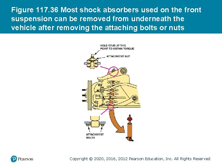
SHOCK ABSORBERS AND STRUTS (2 OF 2) • Front Shock Replacement – Most front shock absorbers can be replaced either with the vehicle still on the ground or while on a hoist. – Special sockets and other tools are available to remove the nut from the shocks that use a single mounting stem. – The removal of the lower mounting of most front shock absorbers usually involves the removal of two bolts. – Reverse the removal procedure to install replacement shock absorbers. Copyright © 2020, 2016, 2012 Pearson Education, Inc. All Rights Reserved
Figure 117. 36 Most shock absorbers used on the front suspension can be removed from underneath the vehicle after removing the attaching bolts or nuts Copyright © 2020, 2016, 2012 Pearson Education, Inc. All Rights Reserved
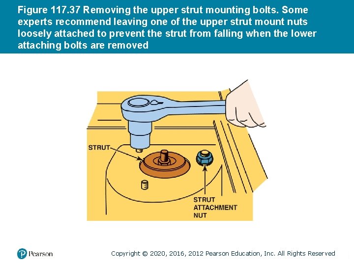
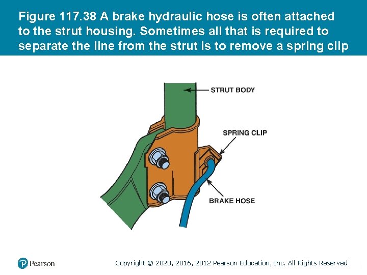
MACPHERSON STRUT REPLACEMENT (1 OF 2) • On most vehicles equipped with Mac. Pherson strut suspensions, strut replacement involves the following steps. – Hoist the vehicle, remove the wheels, and mark the attaching bolts/nuts. – Remove the upper strut mounting bolts except for one to hold the strut until ready to remove the strut assembly. – Remove the brake caliper or brake hose from the strut housing. Copyright © 2020, 2016, 2012 Pearson Education, Inc. All Rights Reserved
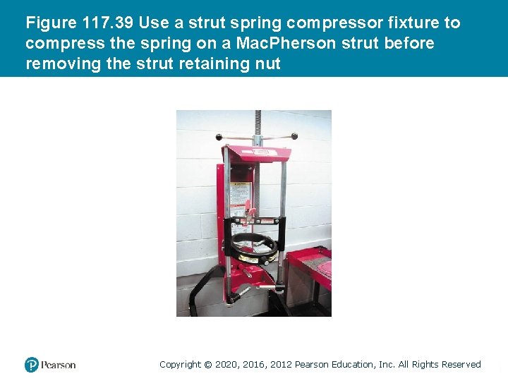
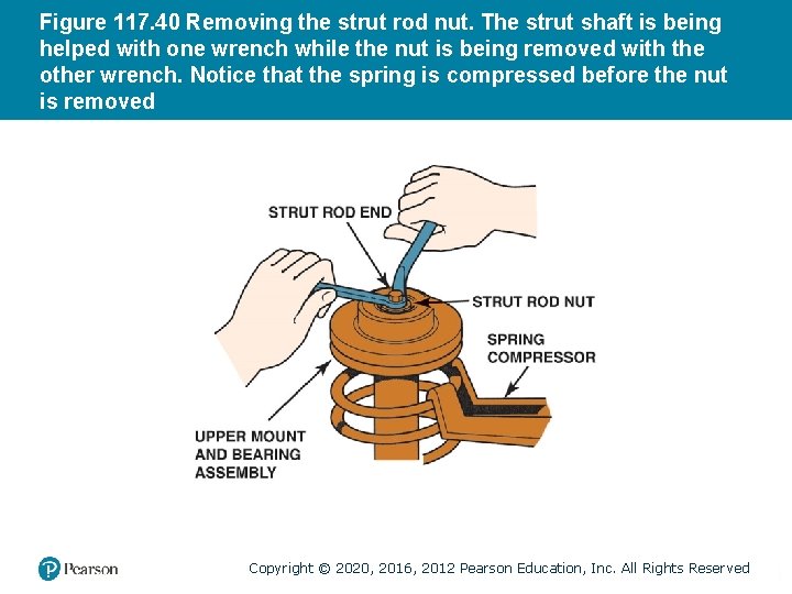
MACPHERSON STRUT REPLACEMENT (2 OF 2) • Replacement Step Continued… – After removing all lower attaching bolts, remove the final upper strut bolt and remove the strut assembly from the vehicle. – Place the strut assembly into a strut spring compressor fixture. – Compress the coil spring enough to relieve the tension on the strut rod nut. – After removing the strut rod nut, remove the upper strut bearing assembly and the spring. Copyright © 2020, 2016, 2012 Pearson Education, Inc. All Rights Reserved
Figure 117. 37 Removing the upper strut mounting bolts. Some experts recommend leaving one of the upper strut mount nuts loosely attached to prevent the strut from falling when the lower attaching bolts are removed Copyright © 2020, 2016, 2012 Pearson Education, Inc. All Rights Reserved
Figure 117. 38 A brake hydraulic hose is often attached to the strut housing. Sometimes all that is required to separate the line from the strut is to remove a spring clip Copyright © 2020, 2016, 2012 Pearson Education, Inc. All Rights Reserved
Figure 117. 39 Use a strut spring compressor fixture to compress the spring on a Mac. Pherson strut before removing the strut retaining nut Copyright © 2020, 2016, 2012 Pearson Education, Inc. All Rights Reserved
Figure 117. 40 Removing the strut rod nut. The strut shaft is being helped with one wrench while the nut is being removed with the other wrench. Notice that the spring is compressed before the nut is removed Copyright © 2020, 2016, 2012 Pearson Education, Inc. All Rights Reserved
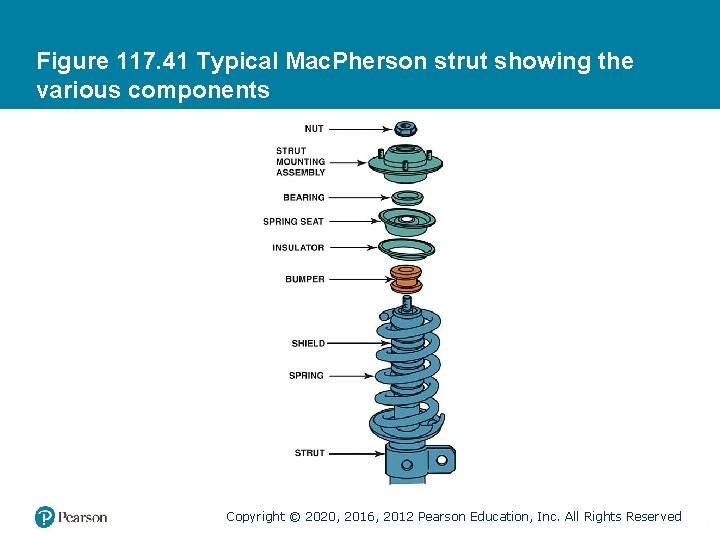
Figure 117. 41 Typical Mac. Pherson strut showing the various components Copyright © 2020, 2016, 2012 Pearson Education, Inc. All Rights Reserved
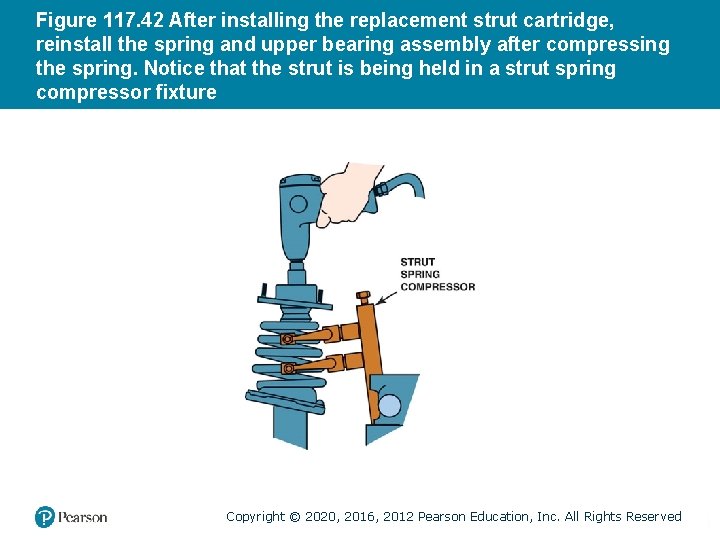
Figure 117. 42 After installing the replacement strut cartridge, reinstall the spring and upper bearing assembly after compressing the spring. Notice that the strut is being held in a strut spring compressor fixture Copyright © 2020, 2016, 2012 Pearson Education, Inc. All Rights Reserved
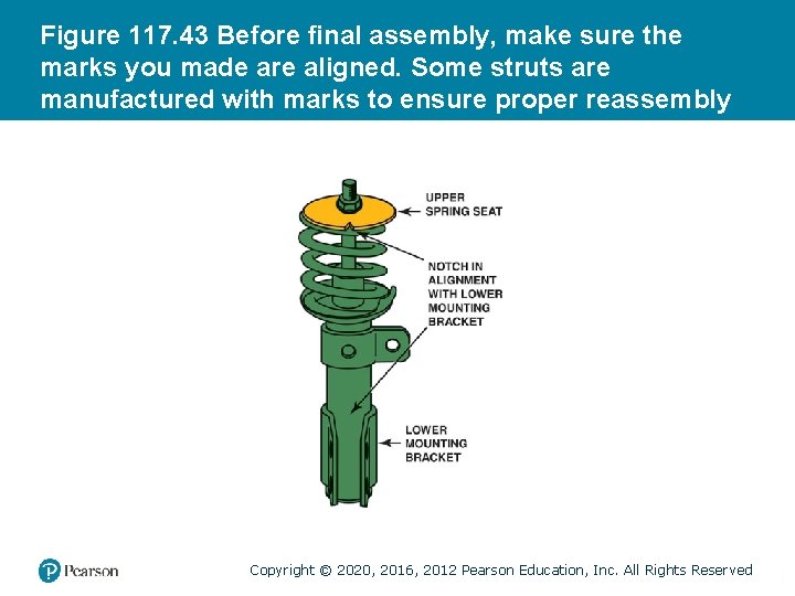
Figure 117. 43 Before final assembly, make sure the marks you made are aligned. Some struts are manufactured with marks to ensure proper reassembly Copyright © 2020, 2016, 2012 Pearson Education, Inc. All Rights Reserved
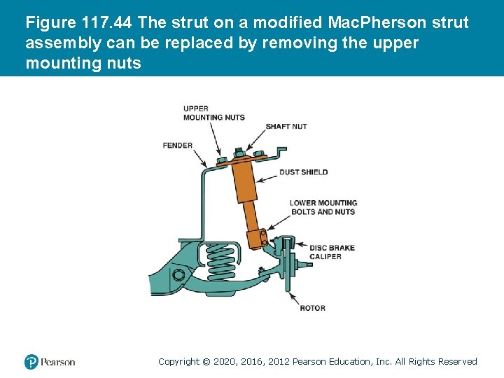
Figure 117. 44 The strut on a modified Mac. Pherson strut assembly can be replaced by removing the upper mounting nuts Copyright © 2020, 2016, 2012 Pearson Education, Inc. All Rights Reserved
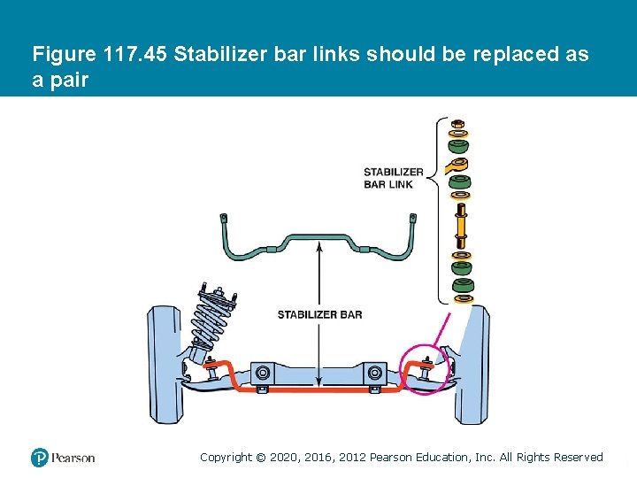
STABILIZER BAR LINKS AND BUSHINGS • Diagnosis – The most common symptom of defective stabilizer bar links or bushings is noise while turning, especially over bumps. • Replacement – Stabilizer links are usually purchased as a kit consisting of replacement rubber bushings, retainers, a long bolt, and spacer with a nut and lock nut. – Stabilizer bar bushing replacement involves the removal (unbolting) of the bushing retainers that surround the bushing. Copyright © 2020, 2016, 2012 Pearson Education, Inc. All Rights Reserved
Figure 117. 45 Stabilizer bar links should be replaced as a pair Copyright © 2020, 2016, 2012 Pearson Education, Inc. All Rights Reserved
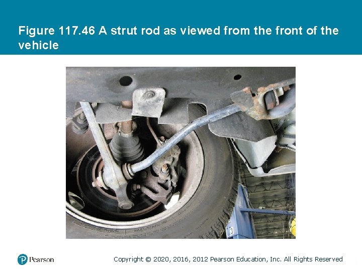
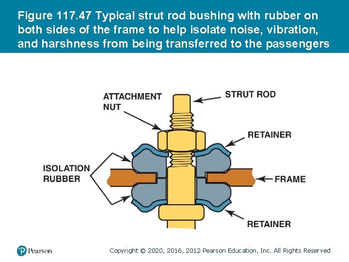
STRUT ROD BUSHINGS • Diagnosis – When strut rod bushings fail, the lower control arm can move forward and backward during braking or when hitting bumps in the road. • Replacement – The strut rod must be removed from the vehicle and then the replacement rubber bushings can be installed. Copyright © 2020, 2016, 2012 Pearson Education, Inc. All Rights Reserved
Figure 117. 46 A strut rod as viewed from the front of the vehicle Copyright © 2020, 2016, 2012 Pearson Education, Inc. All Rights Reserved
Figure 117. 47 Typical strut rod bushing with rubber on both sides of the frame to help isolate noise, vibration, and harshness from being transferred to the passengers Copyright © 2020, 2016, 2012 Pearson Education, Inc. All Rights Reserved
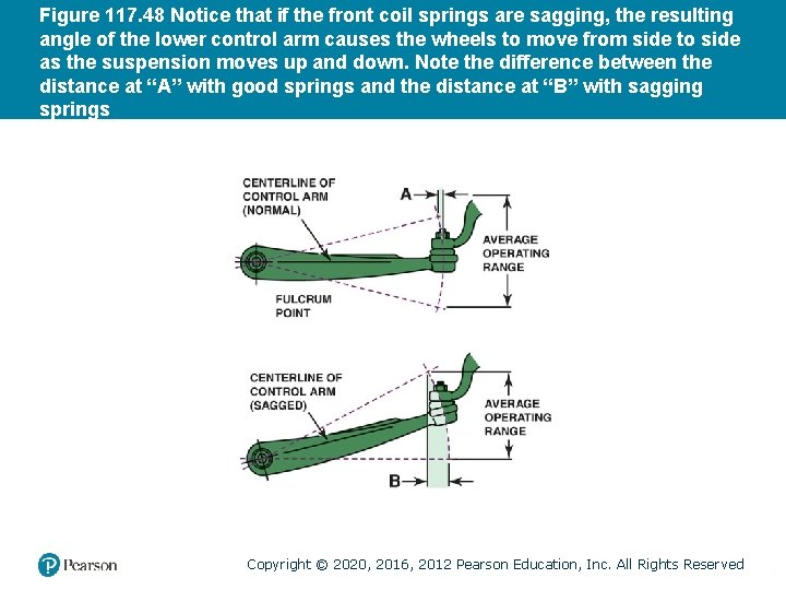
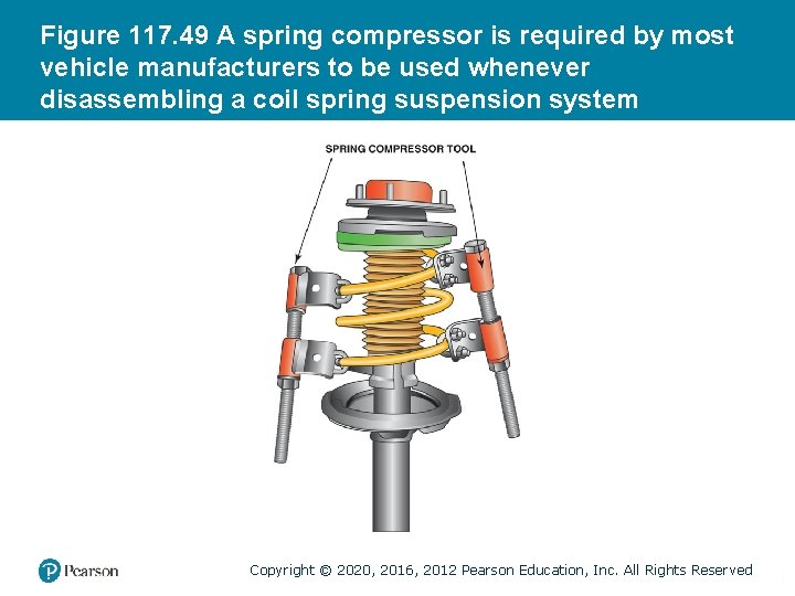
FRONT COIL SPRINGS • Diagnosis – Sagging springs can cause the vehicle to bottom out against the suspension bumpers, and cause the tires to slide laterally (side to side) across the pavement. • Replacement – – Springs should be replaced in pairs. Several aftermarket alternatives are available. Care should be exercised when compressing a spring. Follow manufacturers procedures when replacing springs. Copyright © 2020, 2016, 2012 Pearson Education, Inc. All Rights Reserved
Figure 117. 48 Notice that if the front coil springs are sagging, the resulting angle of the lower control arm causes the wheels to move from side to side as the suspension moves up and down. Note the difference between the distance at “A” with good springs and the distance at “B” with sagging springs Copyright © 2020, 2016, 2012 Pearson Education, Inc. All Rights Reserved
Figure 117. 49 A spring compressor is required by most vehicle manufacturers to be used whenever disassembling a coil spring suspension system Copyright © 2020, 2016, 2012 Pearson Education, Inc. All Rights Reserved
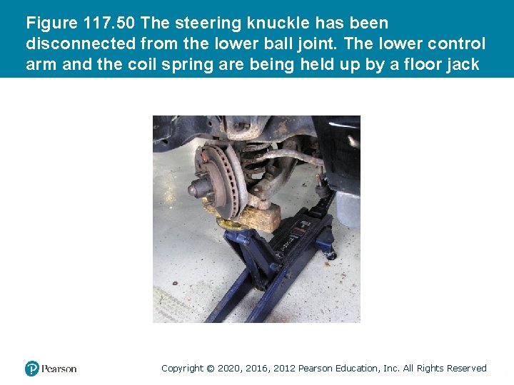
Figure 117. 50 The steering knuckle has been disconnected from the lower ball joint. The lower control arm and the coil spring are being held up by a floor jack Copyright © 2020, 2016, 2012 Pearson Education, Inc. All Rights Reserved
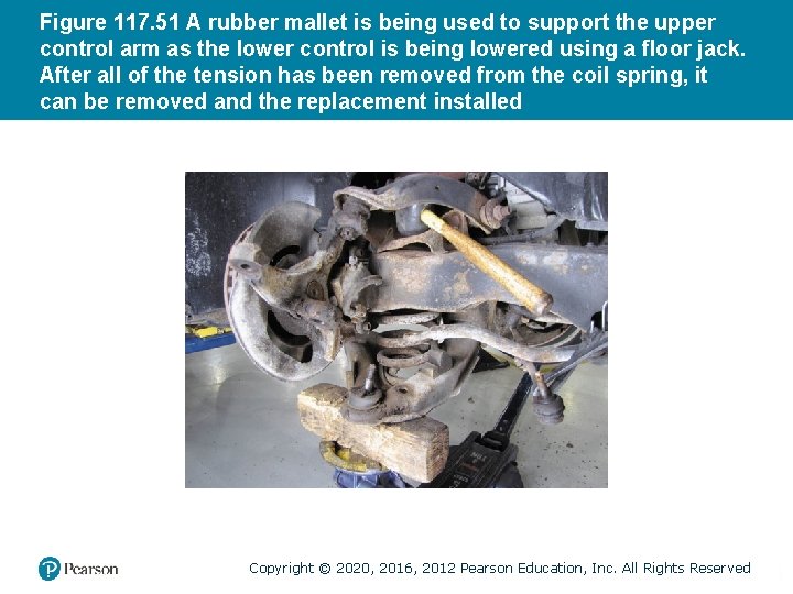
Figure 117. 51 A rubber mallet is being used to support the upper control arm as the lower control is being lowered using a floor jack. After all of the tension has been removed from the coil spring, it can be removed and the replacement installed Copyright © 2020, 2016, 2012 Pearson Education, Inc. All Rights Reserved
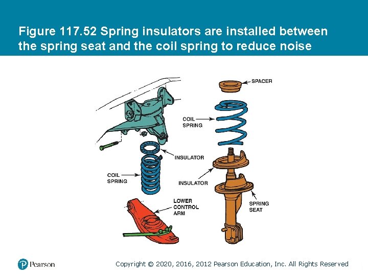
Figure 117. 52 Spring insulators are installed between the spring seat and the coil spring to reduce noise Copyright © 2020, 2016, 2012 Pearson Education, Inc. All Rights Reserved
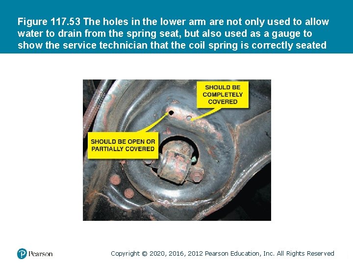
Figure 117. 53 The holes in the lower arm are not only used to allow water to drain from the spring seat, but also used as a gauge to show the service technician that the coil spring is correctly seated Copyright © 2020, 2016, 2012 Pearson Education, Inc. All Rights Reserved
QUESTION 3: ? What are the symptoms of a failed coil spring? Copyright © 2020, 2016, 2012 Pearson Education, Inc. All Rights Reserved
ANSWER 3: Vehicle sags, suspension bottoms out and tire slide on the pavement. Copyright © 2020, 2016, 2012 Pearson Education, Inc. All Rights Reserved
STEERING KNUCKLES • Diagnosis – Unless a thorough inspection is performed during a wheel alignment, a bent steering knuckle is often overlooked. • Replacement – If the steering knuckle is bent or damaged, it must be replaced. Copyright © 2020, 2016, 2012 Pearson Education, Inc. All Rights Reserved
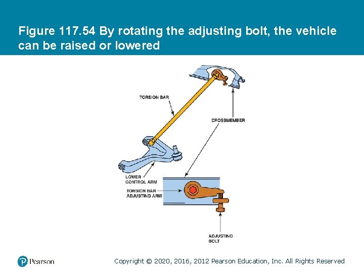
TORSION BARS • Adjustment – Most torsion bar suspensions are designed with an adjustable bolt to permit the tension on the torsion bar to be increased or decreased to change the ride height. – Adjustments are typically made during an aligment. Copyright © 2020, 2016, 2012 Pearson Education, Inc. All Rights Reserved
Figure 117. 54 By rotating the adjusting bolt, the vehicle can be raised or lowered Copyright © 2020, 2016, 2012 Pearson Education, Inc. All Rights Reserved
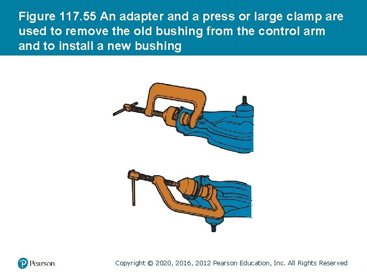
CONTROL ARM BUSHINGS • Diagnosis – Defective control arm bushings are a common source of vehicle handling and suspension noise problems. • Replacement – To remove an old bushing from a control arm, the control arm must first be separated from the suspension and/ or frame of the vehicle. – Bushings are typically pressed in and out of the control arm. – Some bushings are not serviceable. Copyright © 2020, 2016, 2012 Pearson Education, Inc. All Rights Reserved
Figure 117. 55 An adapter and a press or large clamp are used to remove the old bushing from the control arm and to install a new bushing Copyright © 2020, 2016, 2012 Pearson Education, Inc. All Rights Reserved
STRUT REPLACEMENT Copyright © 2020, 2016, 2012 Pearson Education, Inc. All Rights Reserved
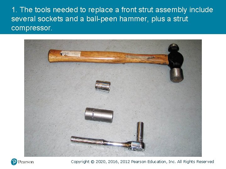
1. The tools needed to replace a front strut assembly include several sockets and a ball-peen hammer, plus a strut compressor. Copyright © 2020, 2016, 2012 Pearson Education, Inc. All Rights Reserved
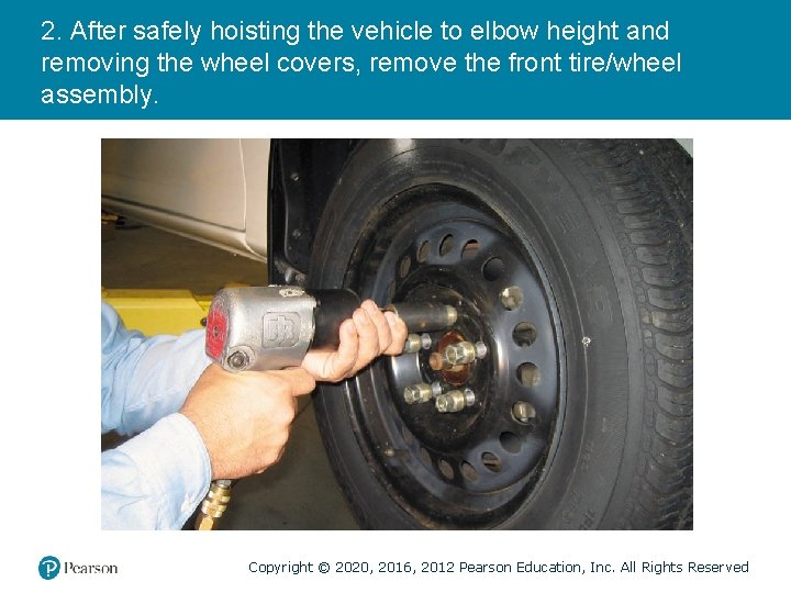
2. After safely hoisting the vehicle to elbow height and removing the wheel covers, remove the front tire/wheel assembly. Copyright © 2020, 2016, 2012 Pearson Education, Inc. All Rights Reserved
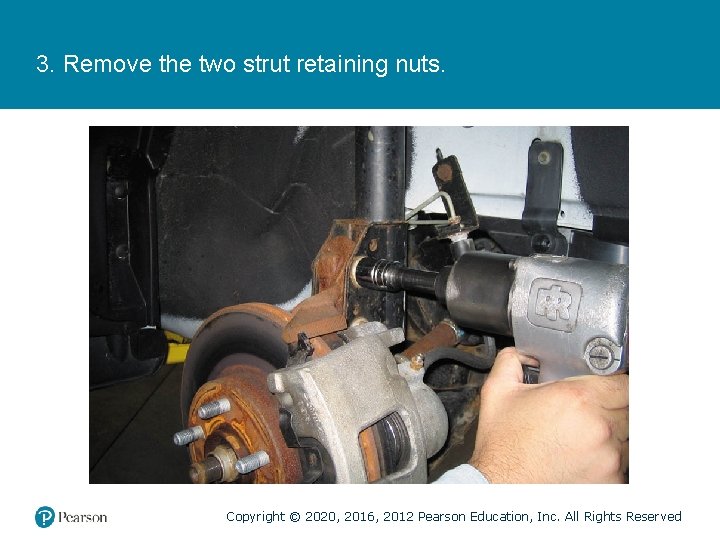
3. Remove the two strut retaining nuts. Copyright © 2020, 2016, 2012 Pearson Education, Inc. All Rights Reserved
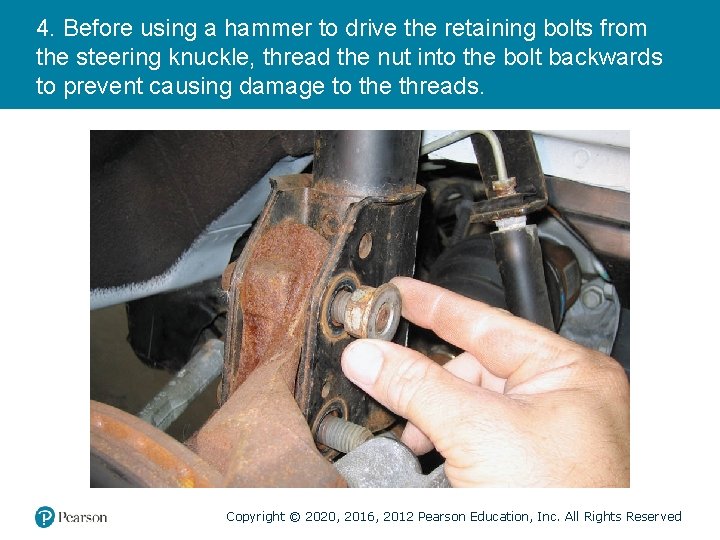
4. Before using a hammer to drive the retaining bolts from the steering knuckle, thread the nut into the bolt backwards to prevent causing damage to the threads. Copyright © 2020, 2016, 2012 Pearson Education, Inc. All Rights Reserved
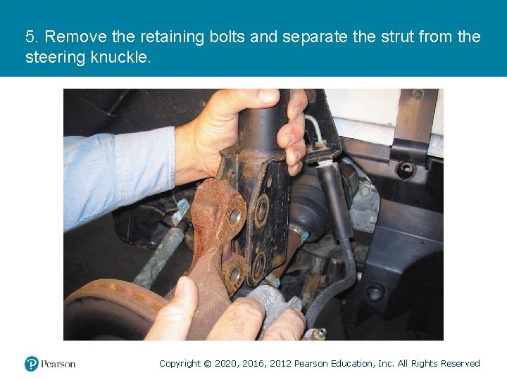
5. Remove the retaining bolts and separate the strut from the steering knuckle. Copyright © 2020, 2016, 2012 Pearson Education, Inc. All Rights Reserved
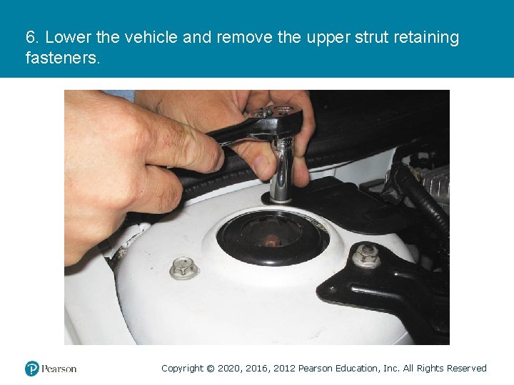
6. Lower the vehicle and remove the upper strut retaining fasteners. Copyright © 2020, 2016, 2012 Pearson Education, Inc. All Rights Reserved
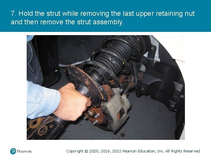
7. Hold the strut while removing the last upper retaining nut and then remove the strut assembly. Copyright © 2020, 2016, 2012 Pearson Education, Inc. All Rights Reserved
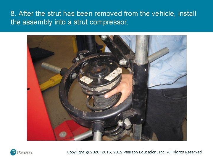
8. After the strut has been removed from the vehicle, install the assembly into a strut compressor. Copyright © 2020, 2016, 2012 Pearson Education, Inc. All Rights Reserved
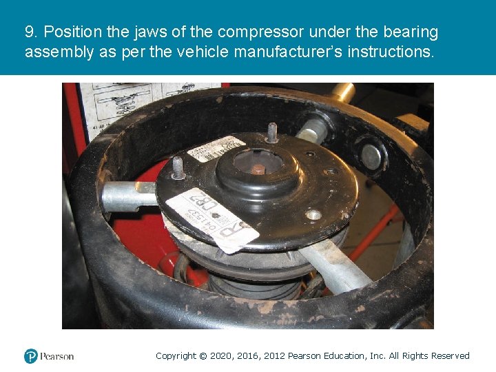
9. Position the jaws of the compressor under the bearing assembly as per the vehicle manufacturer’s instructions. Copyright © 2020, 2016, 2012 Pearson Education, Inc. All Rights Reserved
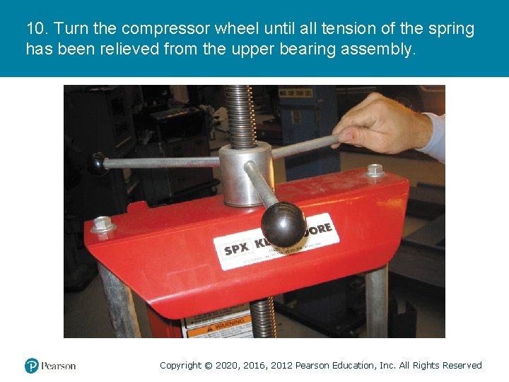
10. Turn the compressor wheel until all tension of the spring has been relieved from the upper bearing assembly. Copyright © 2020, 2016, 2012 Pearson Education, Inc. All Rights Reserved
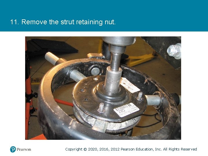
11. Remove the strut retaining nut. Copyright © 2020, 2016, 2012 Pearson Education, Inc. All Rights Reserved
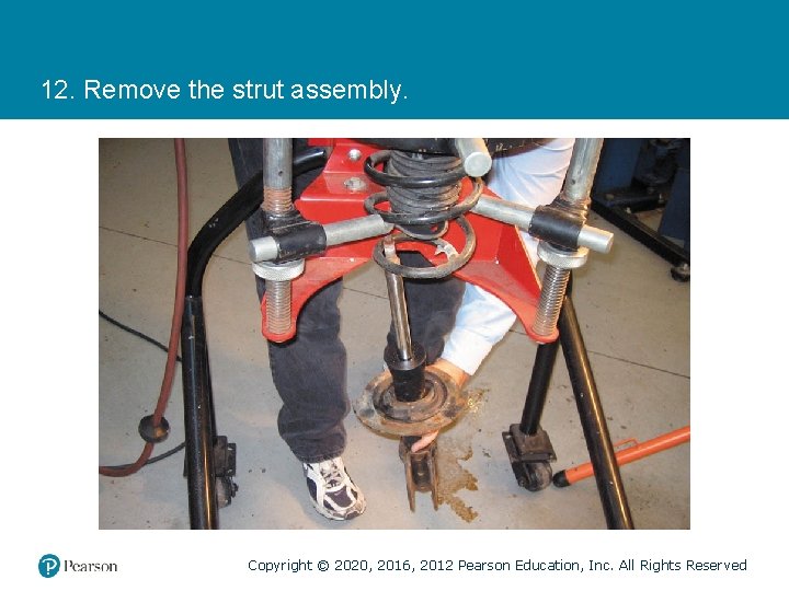
12. Remove the strut assembly. Copyright © 2020, 2016, 2012 Pearson Education, Inc. All Rights Reserved
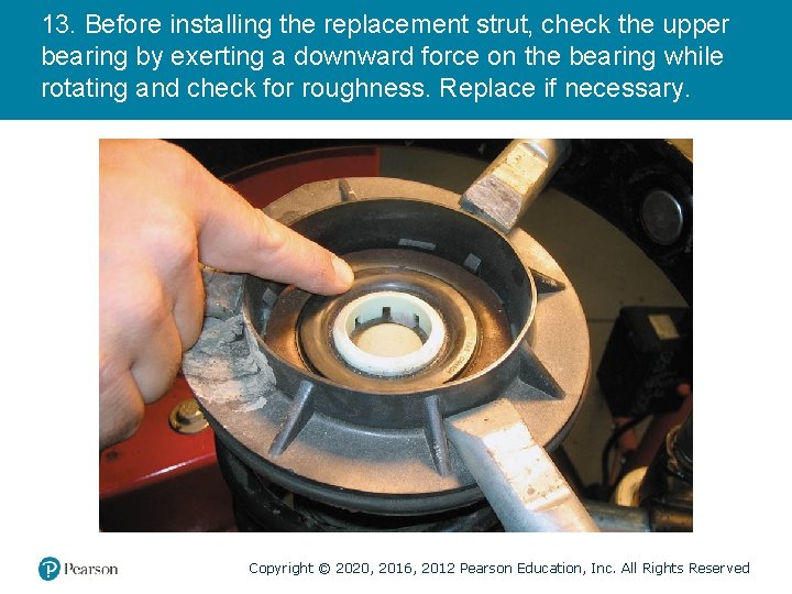
13. Before installing the replacement strut, check the upper bearing by exerting a downward force on the bearing while rotating and check for roughness. Replace if necessary. Copyright © 2020, 2016, 2012 Pearson Education, Inc. All Rights Reserved
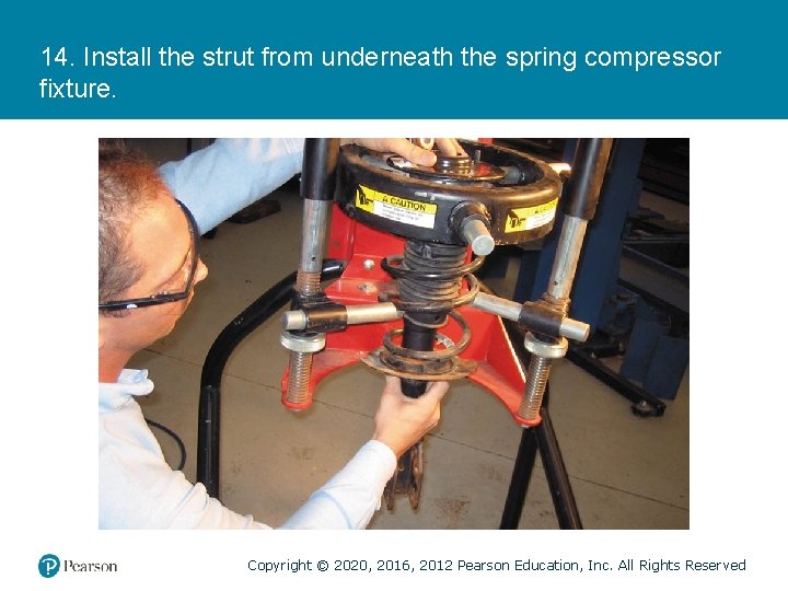
14. Install the strut from underneath the spring compressor fixture. Copyright © 2020, 2016, 2012 Pearson Education, Inc. All Rights Reserved
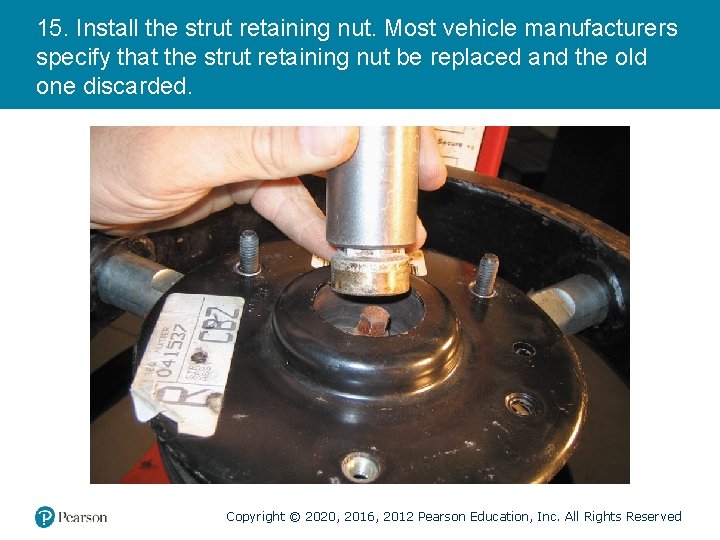
15. Install the strut retaining nut. Most vehicle manufacturers specify that the strut retaining nut be replaced and the old one discarded. Copyright © 2020, 2016, 2012 Pearson Education, Inc. All Rights Reserved
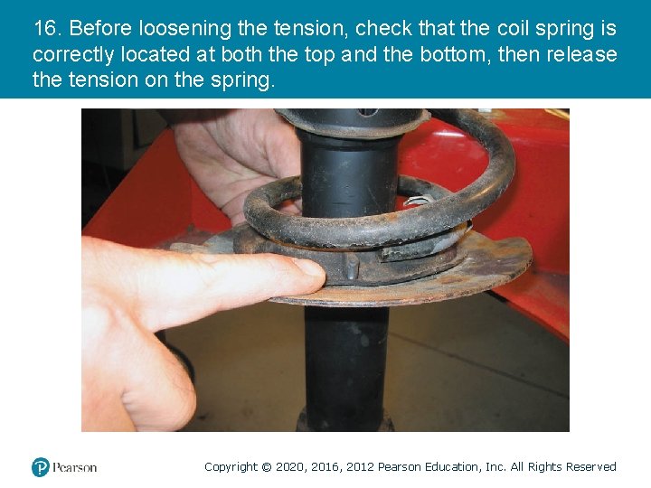
16. Before loosening the tension, check that the coil spring is correctly located at both the top and the bottom, then release the tension on the spring. Copyright © 2020, 2016, 2012 Pearson Education, Inc. All Rights Reserved
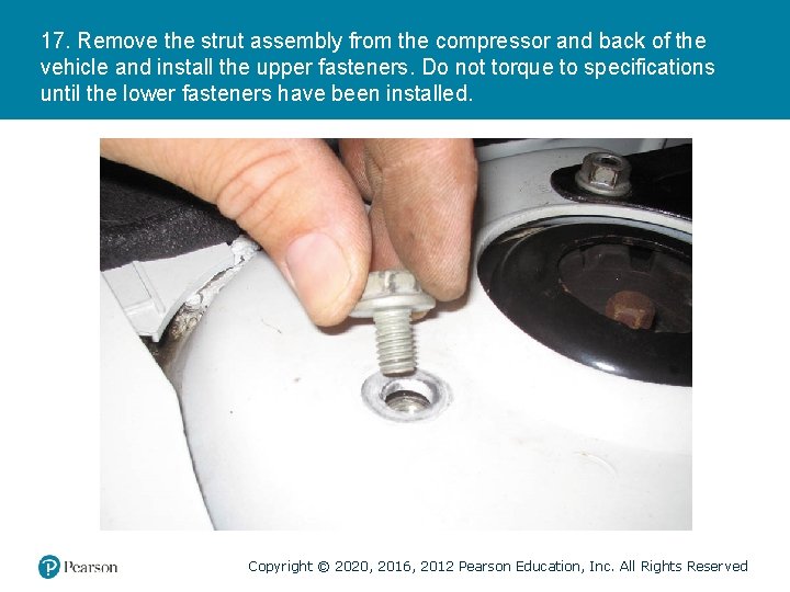
17. Remove the strut assembly from the compressor and back of the vehicle and install the upper fasteners. Do not torque to specifications until the lower fasteners have been installed. Copyright © 2020, 2016, 2012 Pearson Education, Inc. All Rights Reserved
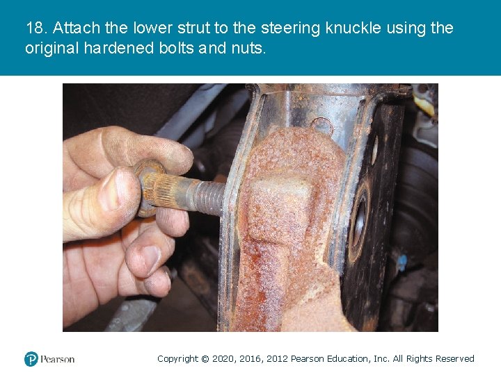
18. Attach the lower strut to the steering knuckle using the original hardened bolts and nuts. Copyright © 2020, 2016, 2012 Pearson Education, Inc. All Rights Reserved
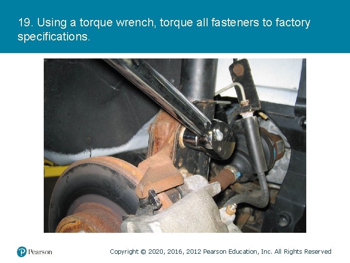
19. Using a torque wrench, torque all fasteners to factory specifications. Copyright © 2020, 2016, 2012 Pearson Education, Inc. All Rights Reserved
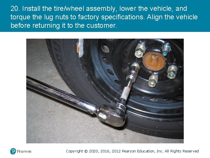
20. Install the tire/wheel assembly, lower the vehicle, and torque the lug nuts to factory specifications. Align the vehicle before returning it to the customer. Copyright © 2020, 2016, 2012 Pearson Education, Inc. All Rights Reserved
Copyright © 2020, 2016, 2012 Pearson Education, Inc. All Rights Reserved