Automatic Tensile Tester 4000 Group 6 Alan Beauchamp

Automatic Tensile Tester 4000 Group 6 Alan Beauchamp Justin Ewing Devon Jackson

Introduction �Material testing is a very expensive and exclusive exercise, from sending the material out to buying a specific test frame. �When the test frames are purchased for local use, they come with software that is cumbersome for the computers that use them, forcing them to use all of their memory. �This project enters with the goal to make a comparable test frame that is cost efficient and is autonomous, being able to function without a computer.

Introduction �This product is called the Automatic Tensile Tester 4000 �A small scale test device for creep, creep-fatigue, and creep crack growth testing. �Creep is a deformation that occurs below the yield strength of a material at temperatures above 40% of the melting temperature. �Fatigue is the non-recoverable loss in strength that occurs when a material is subject to cyclic loading. �Often, the effects of creep and fatigue are idealized as damage. This device will be used to study those effects, because creep damage is the primary design consideration for steam and gas turbine OEM’s.

Goals � � � � Low cost Accurate Portable Work without a computer connection Must be able to pause/re-edit/resume Must be able to data dump to or read data from USB Must be able to manually control entire experiment from box Must be able to program experiment from computer connection Control two material testers simultaneously Interfacing accessible on web (Linux, Windows) LCD must display status and cycle Implement fat 16 file system for data logging Status light for experiment Wall powered Plug and play components Software must be user friendly and open source

Specifications �Automatic command/data retrieval for 1 hour �Measure temperature accurate to ± 2 o F �Rate temperatures from 0 o F to 1000 o F �Measure force accurate to ±. 2% �Accurately measure strain gauge factor ± 10 �Be able to hold and test loads up to 2000 lb �Be able to run 3 tests (specified) for 15 minutes each �Control box 8” and weight no more than 10 pounds

Power Distribution Justin Ewing

Power Requirements Voltage needed by part: �Load Cell – up to 18 V �LVDT – up to 18 V �Microcontroller – 5 V �INA 118 Instrumentation Amplifier - ± 12 V �LM 741 Op-Amp - ± 12 V �LM 339 Comparator – 5 V �Linear Actuator – 12 V, 20 A for max power

Sensors and Control Power All components and sensors will be powered by the MSCA-0303, a 15 V, 2 A power source. A combination of regulators will be used to distribute power to all the components.

Sensors and Control Power � 4 7812 Regulators �LCD Screen �INA 118 Instrumentation Amplifier, 2 741 Op-Amps � 555 Timer for Negative Rails �Load Cell and LVDT � 2 7805 Regulators �H-Bridge �Microcontroller � 1 LM 317 Regulator �SD Card

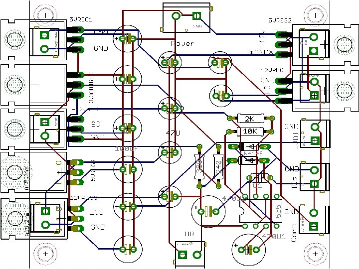
Sensors and Control Power The PCB is designed so that: � All of the common components are on the same side of the board. � Similar parts are next to each other Located on the top is the voltage input and on the bottom is the H-Bridge.

Actuator Power For the Actuator’s power source, we chose the MMK 320 S-12. Output of 300 W (12 V, 25 A) at maximum output which will also power 2 small fans Self-ventilating convection system.

Actuator Power �The same power source will activate two cooling fans, that will provide air the rest of the components in the case and allow for convection cooling.

Power Control �Both power sources use wall power by means of stripped computer wire. �Main on/off will be the switch on the power strip. �Emergency shut off will take the positive outputs of both sources and the input to the devices they control. �Quick and easy installment. �Big Red Button is common sign for emergency

Sensors Justin Ewing & Devon Jackson

Sensors �For the tests performed, we will use the following sensors �Load Cell �Linear Variable Differential Transformer �Thermocouple

Load Cell �Two way load cell that detects both tension and compression � 6 wire-receptacle �Positive and negative outputs at 2 m. V/V �Rated 2000 lbs.
 �Amplifies the difference between the terminals and outputs a voltage")
Load Cell (INA 118) �Amplifies the difference between the terminals and outputs a voltage referenced to ground. �Amplification is: Av = 1 + 50 K/Rg �Our application requires Rg to be 250Ω for a gain Av≈200
 �Uses LM 339 Comparator (opendrain) �Tension (positive input) will yield")
Load Cell (Tension/Compression Sensor) �Uses LM 339 Comparator (opendrain) �Tension (positive input) will yield LOW output �Compression (negative input) will yield HIGH output. �Output goes to the “sense” line in the MC
 �Designed as a precision rectifier that doesn’t have the")
Load Cell (Full Wave Rectifier) �Designed as a precision rectifier that doesn’t have the loss of the diode version �Quick response to MC �Rejects ALL negative voltage, protects MC

Load Cell �The two previous circuits will take both of their inputs from the output of the INA 118 �Instead of using the datasheet to predict output values of the load cell, we will develop our own calibration system to more accurately determine the load applied.

Linear Variable Difference Transformer �Precise tool to measure displacement � 4 -wire interface �-1. 5 -11 V output (0 -10 V functional)

LVDT �To reduce the output �Like the load cell, the signal to the range of the LVDT will be calibrated MC, we used a voltage so that the initial divider to reduce the position will be the output from 11 V to 5 V “Zero” and displacement will read from the “Zero” �Finally to eliminate the reference. negative response, a diode was placed before the output to protect the microcontroller

Temperature �Thermocouple �PID captures the signal �The data pulled and saved to a file �Specification

Thermocouple �Thermocouple has more range, sensitivity, more cost effective, and more ruggedness � 36" high temperature Type-K Thermocouple with glass braid insulation. �Type-K Thermocouple (Ni-Cr) � 30 gauge stripped and prepped wires �Thermocouple range : -270 to +1372 C (-454 to +2501 F) �Yellow + / Red –

Thermocouple Amplifier AD 595 -AQ • Analog Devices Thermocouple Type-K Amplifier. • The 10 m. V/C analog output interfaces nicely with 10 -bit ADCs found on many types of microcontrollers. ± 3 o C Accuracy • 5 V-15 V Power Supply

PID Controller �Trident and Trident X 2 Digital Process and Temperature Panel Meter �A third party PID temperature controller captures signal from thermocouple �Temperature controller has an channel available for an analog input (i. e. remote set point)

Motor Control Devon L. Jackson

Motor Control �Be able to control the motor manual �Be able to have the ability to go down, reverse, and stop �Be able to apply a certain amount of force as desired by the sponsor �Be able to apply a constant load
")
Actuator �Heavy Duty Linear Actuator (Stroke Size 12", Force 2000 Lbs, Speed 0. 24"/sec)

H-Bridge � An h-bridge is used to convert low-power control signals into high-power drive for motor control as well as other high power applications � The microcontroller connects to the h-bridge's logic level inputs, and the h-bridge converts those low power control signals into high power outputs suitable for driving the motor, controlling the motor's direction, and varying the motor's speed.

• With optional heat sink installed: 30 Amps continuous, 40 Amps peak • With NO heat-sink installed: 10 Amps continuous • 5 to 24 Volts (30 V absolute max) • High frequency PWM, frequencies to 100 k. Hz • ATO style fuse on-board • Status and power indicator LEDs • Convenient FAST-ON blade type connectors • Convenient screw terminals for control logic • Locked anti-phase native control method • Sign magnitude / synchronous rectification also possible • Small size - 2. 5 x 2. 6 inches • High quality 4 -layer board, large ground and power planes • Truth table for the possible control states: EN 1 EN 2 IN 1 IN 2 MOTOR+ MOTOR - Description 0 0 X X OPEN Bridge disabled, motor freewheels 1 1 0 0 GND Motor leads break to GND 1 1 V+ V+ Motor leads break to V+ 1 1 0 1 GND V+ Motor turns CW 1 1 1 0 V+ GND Motor turns CCW

Rocker Switch • Press a button and the actuator will fully extend and will stop once fully extended. Push a button in opposite direction and the actuator will fully retract. In addition, the switch has a middle position that can stop a linear actuator at any point. • Specifications: Switch Operation: 3 positions: On-Off -On Can be used outdoors Circuitry: DPDT Switch Terminals: Quick Connect Actuator / Cap Color: Black Contact Current Max: 10 A Leaded Process Compatible: Yes Mounting Type: 0. 187 in Quick. Connect Tab Ro. HS Compliant: Yes

System Control and Interface Alan Beauchamp

PID control loop The ATT 4000 uses a basic PID feedback control loop. The load is used to calculate the PWM percentage applied to the actuators motor which then to increase or decrease force to the test specimen.
 + (Ki *")
PID Controller �PWM Signal = Motor Speed = (Kp * P) + (Ki * I) + (Kd * D) �P = error �Desired Load – Load Cell Reading(Converted to number ranging from 0 to 1023) �I = Integral �I = (I * IDamp) + (error * Dt) �Sum of all the errors. �Controlled using a damping variable �Resets if error is close to zero �D = Derivate �Current error – previous error

System Logic

PID Constant Effect Table Parameter Rise time Overshoot Settling time Steady. Stability state error Kp Decrease Increase Decrease Ki Decrease Increase Small change Increase Kd Minor decrease No effect in Improve theory if Kd small Degrade Decrease Degrade significantl y

Data Storage Device �The A. T. T 4000 uses SD / MMC Card for data logging. � SD transfer rate of 80– 160 Mbit/s � Capacity 4 GB to 32 GB � Small footprint. 24. 0 mm x 32. 0 mm max � File System: Fat 16 �The Sd. Fat V 2 library is utilized on the data logging microcontroller to allow access Fat 16/32 partitions on the SD card.

Data Acquisition The output file will consist of raw ADC conversion values from the microcontroller’s ADC pins. Output Type Cycle Unsigned long Load unsigned int Error unsigned int The A. T. T 4000 logs data using the comma-separated file type. CSV is a simple format than is easily imported into a standard program such as excel or open office spreadsheet. Temp unsigned int Displacement unsigned int Motor Displacement unsigned int PWM unsigned char Seconds Unsigned long To the left we have the break up of each line of data in the CSV file. 50 day count Unsigned long

User & Communication Interface The GUI a fully usable interface that can on control all aspect of the device. The physical will be limited to viewing status, starting/stopping, pausing/resuming and position for setup of specimen. The FTDI FT 232 RL allows the user to connect an USB mini cable to our devices when interfacing with the GUI on a PC. USB reliable, durable, and it’s usually plug and play. The alternative to using a USB to serial converter on the device side would be to use a serial to USB converter on the computer side. Specification Start Stop Pause Resume Temperature reading Strain Gauge Reading Motor PWM Status Motor Control Transfer Data Set Constants Load Input File Load Setup File GUI X X X Physical X X X X X

Atmega 328 Data Buffer Data transferred to and from the GUI and the atmega 328 p we uses a byte array data buffer. Example: byte a[64] = Cycle/Strain/Load/Tem p/Extra/…. The GUI will request information also using a byte array consisting of operation values and data values. Byte array Data Buffer PC GUI Interface Op Op Code Data Return Get File 0000 Name of File on SD card you want to download File Load Input File 0001 Path of Input file on PC File Load Success or Fail Get Current Cycle 0010 Data NONE Return 32 byte array with status Stop 0011 NONE Kill test Start 0100 NONE Run startup script Pause 0101 NONE Halt test

Event Name External Stimuli External Responses Internal data and state Application Opened User opens application Application GUI displays with main window. If System runs initialization script. System experiment is currently running user directed in Active state ready for user response to experiment status window. Initialize New Experiment User selects option to start User is directed to experiment configuration new experiment page, with require textbox inputs for configuration. System is in stand by awaiting proper configuration data include experiment type, duration and other parameters. Load / Confirm User either submits initial User is directed to main experiment status Experiment experiment information or window /w Current status information settings load old experiment available. configuration file Query current experiment information. Goes back to Active state Verify Input File Use selects file verification Application verification status bar appears or user try to start experiment System checks each line of input file. Back to active state if no error, prompt user if error. Run experiment User hits play button Application experiment status bar appears. User prompt for error or to start experiment System initialize and a test all components of the system. Including creation of all necessary files. Go back to Active state Pause experiment User hits play button User is directed main experiment status window. System backups all current statuses and marks cycle position. Save all information to SD card. Stop experiment User select stop button or experiment is completed. User is prompted with completion status then Verify all information is logged, save final directed main experiment status window. status information. Return to active state Application Closed User closes application Application prompted user to assure user want System is in Inactive state to exit

Main Interface • Once a user connects to the device if an experiment is currently running, receive real time statuses of the current running experiment. The user is also able to pause , resume and terminate a currently running experiment. The raw data is received from the microcontroller and converted into the proper measurements. • If an experiment is not running a user will be able to position the translating piece to secure a test specimen in place, using either the rocker switch or the button on in the interface. Once a experiment has started all motor controls will be disabled.

Input File • The input interface is used to defined the PID parameters, load per cycle, fail cases, and conversion factors for an experiment. The user friendly interface automatically calculates number of repeats or desired experiment time when either field is updated. • The user will be able to set fail switches for load, motor displacement , and L. V. D. T displacement. These fail switches will automatically stop the current running experiment if the specimen should fail before the total running time. • The conversion table variable are set to allow the microcontroller to convert load, strain , and temperature for PID control and LCD display.

Output File � The raw data received from ATT 4000 is automatically converted using the value in the conversion table available on the bottom of the interface. � Once the output file is loaded the user may generate a range file using its corresponding input file. Once a range file is generated the user may export specific ranges and/or cycles; save and analysis the data in their preferred data analysis program. � The user may also export any range of data using the start and end fields.

Calibration �This interface allow a user to calibration any load or L. V. D. T connected to the ATT 4000. Each sample is a average of 500 samples of the device being calibrated. This allow the user to have a analog to digital to Load or millimeter conversion and vise versa. �Skipping the middle conversion from pounds to volts to adc.

Atmega 328 P The two atmega 328 p control the following aspect of the A. T. T 4000 • Data logging • Serial communication to GUI • PID algorithm execution • Motor Control • Analog Readings • Fail condition algorithm • LCD output • Physical control interface Specification • Operating Voltage 5 V • Clock Speed 16 MHz • 32 Ki. B Flash memory • 1 Ki. B EEPROM • 2 Ki. B SRAM • 14 Digital I/O Pins (6 PWM) • 6 ADC input pins

Analog devices to Atemga 328 P The schematic to the left shows the configuration of the 3 analog devices and the atmega 38 p. The load cell and thermocouple outputs require amplification before they can be sent to the microcontroller, this allow the signal coming out to max out at 5 volts. The amplification circuit show is a black box representation of the actually circuit show in previous sections. ADC ports on the atmega 328 p 0, 2, 4 receive signals from the load cell, thermocouple and strain gain respectively.

Micro SD Card – Atmega 328 p schematic • The SD card interfaces with the data logging microcontroller through the Serial Peripheral Interface Bus a 4 -wire interface. • The micro SD card has a operating range of 2. 6 – 3. 6 volts because of this a voltage dividers circuits are used for communicating between the devices. • The data logging controller communicates with the main controller using a serial interface. Communicating at a baud rate of 9600.

Physical Interface • We incorporates a 20 by 2 rs 232 alpha numeric display with a arcade style push button interface. This interface lets the user check the current status of all components of the system during a running experiment. While the device is either connected or disconnect for a PC. • The interface cycles 3 pages of information. The pages cycle every 3 seconds. Page Format Page 1 Cycle # Time Page 2 Load Error Page 3 Displacement Temperature

PCB Design

Conclusion �This project proves that it is feasible to create a test frame and interface for a fraction of the cost of a popular model. �MTS Frame ≈ $20, 000 �A. T. T. 4000 ≈ $1, 500

Description QTY Cost Total Actuator Motor 1 $ 250. 00 $250. 00 Atmega 328 P 2 $ 4. 30 $8. 60 H-Bridge 1 $ 120. 00 $120. 00 5 Volt Regulator 1 $ 1. 59 $1. 59 3. 3 Volt Regulator Sparkfun Serial LCD 1 1 $ 1. 95 $ 12. 95 $1. 95 $12. 95 Ethernet Shield Micro SD Card 1 1 $ 45. 95 $ 9. 95 $45. 95 $9. 95 SD Breakout Board 1 $ 9. 95 $9. 95 Load Cell 1 $ 475. 00 $475. 00 Strain Gauge 1 $ 330. 00 $330. 00 Thermocouple 1 $ 5. 00 $5. 00 PCB 1 $ 121. 00 $121. 00 10 nf Capacitors 2 $ 0. 45 $0. 90 100 nf Capacitors 2 $ 0. 35 $0. 70 FT 245 RL Breakout Board 1 $ 14. 95 $14. 95 USB Cable 1 $ 5. 00 $5. 00 12 AWG Wire 1 $ 10. 00 $10. 00 Project Box 1 $ 6. 99 $6. 99 Buttons 4 $ 0. 50 $2. 00 Rocker Switch 1 $ 20. 00 $20. 00 10 $ 0. 35 $3. 50 2 $ 1. 99 $3. 98 Screw Terminals- 2 pin 20 $ 0. 95 $19. 00 Screw Terminals- 3 pin 2 $ 0. 95 $1. 90 Arduino Total 1 $ 29. 95 $1, 510. 81 LED Op Amps
- Slides: 54