Automatic Gain Control Circuit for Quartz Crystal Microbalance
 By Abhijat Goyal & Saliya")
Automatic Gain Control Circuit for Quartz Crystal Microbalance (QCM) By Abhijat Goyal & Saliya Subasinghe

What is QCM Quartz Top Electrode Bottom Electrode Addition of mass on the surface of the resonator causes changes in its resonance frequency. Sauerbrey Equation

Objective of the Circuit p Maintain the amplitude of oscillation to be constant. p Compensate for the change in motional resistance (Rm) due to change of ambience of the resonating crystal. p We need a circuit with feedback control which can dynamically adjust to changing Rm of the oscillator, in order to sustain oscillations.

Proposed circuit Mixer Simple Amplifier ½ Wave Rectifier Unity Gain Stage Integrator

Proposed circuit Offset Control Mixer Unity Gain Buffer Output Buffers Integrator

Integrator

This resistor and capacitor determine the time constant of the integrator These two resistor bias the opamp at 2. 5 V Average power of this circuit = 1. 9 m. W Maximum power of this circuit = 1. 9 m. W Determines the amplitude of input waveform.

Small high to low transition at input Large low to high transition at input Large high to low transition at input

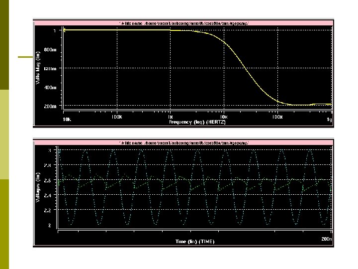
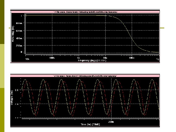
Minimum Attenuation of high Frequency signal passing through

Input-Output curve Idea was to make this part of the curve as less steep as possible.

Multiplier Vout = KRf. Vin 2 Vin 1 – KRf. VTVin 1 + Vin 1 where K = μo. Cox. W/L VT and K are constant If we set Rf =1/(KVT) Vout = (Vin 2 Vin 1)/VT When Vin 1 ≤ Vin 2 - VT G. A. Hadgis, P. R. Mukund, "A novel CMOS monolithic analog multiplier with wide input dynamic range, " vlsid, p. 310, 8 th International Conference on VLSI Design, 1995.

Unity Gain Buffer Compensation

Voltage Buffer using Multiplier p How do we implement a buffer using the circuit topology for the multiplier? p Vout = KRf. Vin 2 Vin 1 – KRf. VTVin 1 + Vin 1 p K is on the order of magnitude 10 -6 p Make Rf small p Then Vout ~ Vin 1

Questions?
- Slides: 16