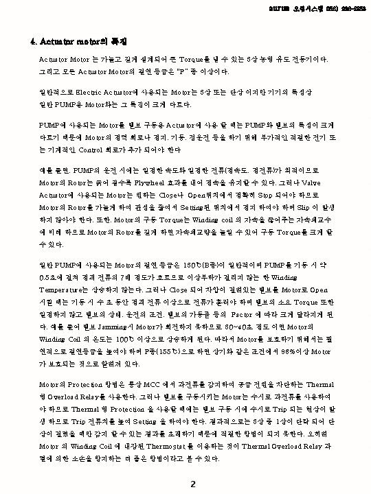
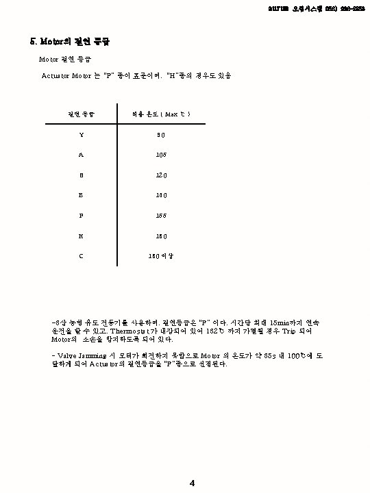
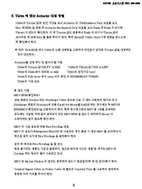
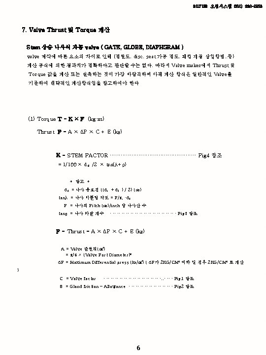
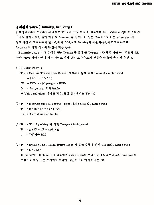
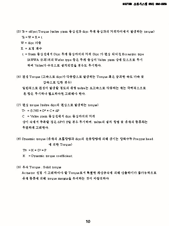
aurum 052 222 2358 3 Actuator Actuator valve
 222 -2358 3. Actuator 종류 Actuator 의 사용은 valve의 자동화를 목적으로")
 222 -2358 Motor Technical Data 3 -Phase AC motor DC motor")
 VALVE 축경 VALVE TYPE LIQUID PARAL")
 222 -2358 예 시 Ex) 10″ #300 Gate valve , Max")
 = (Life")
 222 -2358")
 222 -2358")
 222 -2358")
 222 -2358 Indicate Control unit Hollow shaft / Worm shaft")
 222 -2358")
 222 -2358 AUMA Actuator 명칭 No Designation Type No. Designation Type")
 222 -2358 Designation Type 535. 1 Snap")
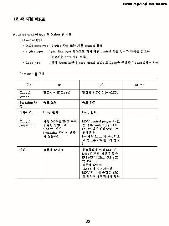
 222 -2358 12. 각 사별 비교표 Rotork Limitorque Biffi EIM Bernard")
 222 -2358 #. Motor Technical Data 3 -Phase AC motor DC")
 222 -2358 #. Motor Technical Data Output speeds for multi-turn actuators")
 222 -2358 #. Flange Dimensions ISO 5210/1 MOUNTING FLANGE TYPE ΦD")
- Slides: 26
aurum 오럼시스템 052) 222 -2358 3. Actuator 종류 Actuator 의 사용은 valve의 자동화를 목적으로 사용되는 일종의 부가 장치로써 제어 방법에 따라 크게 3가지로 구분된다 Actuator의 종류 구 분 설 명 Electric Actuator (전기) Motor 의 회전력과 Gear 의 조합을 이용하여 Valve의 동작 제어 Penumatic Actuator (공압) Cylinder 내의 Piston 또는 Diaphragm를 이용하여 가해지는 압력, 유량, 기체(Gas)의 물리적 에너지에 의한 valve 동작 제어 Hydraulic Actuator (유압) Cylinder 내의 Piston을 이용하여 Water, Oil에 가해지는 압력, 유량의 물리적 에너지 에 의한 Valve 의 동작 제어 운동 원리에 따른 구분 구 분 설 명 적 용 Valve Part turn or Quarter turn ¼ turn Actuator 0˚~90˚ 회전에 사용 가능 Ball, Butterfly, Plug, Damper Multi turn 1회~5000회 까지 회전 가능 Rising , Non-Rising type 에 사용 가능 Lift Valve 에 사용 ( Gate, Globe, Diaphragm, Sluice, Angle ) Rectilinear Motion (직선운동) Multi turn Actuator 에 Linear thrust Unit 를 부착하여 운동에너지 변환 (회전운동 → 직선운 동) Globe, Diaphragm, Damper 1
aurum 오럼시스템 052) 222 -2358 Motor Technical Data 3 -Phase AC motor DC motor Standard voltages 50 Hz : 220 V, 230 V, 240 V, 380 V, 400 V, 415 V, 500 V 60 Hz : 208 V, 230 V, 440 V, 460 V, 480 V, 575 V 50 Hz : 220 V ~ 240 V 60 Hz : 110 V ~ 120 V, 220 V, 110 V, 60 V, 48 V, 24 V Permissible variations ± 10% Motor data Refer to data sheets Design/mounting IM B 9 acc. To IEC 34 -7 Type of motor Squirrel cage Enclosure protection NEMA 4 X , IP 67 NEMA 6 , IP 68 (OPTION) Type of cooling Self-cooling / surface cooling (IC 40 according to IEC 34 -6) Insulation class F according to NEMA MG 1 , tropicalized Electrical connection for motor Up to SA 16. 1 (up to 7. 5 kw) : AUAM plug/socket connector at multi-turn actuator SA 25. 1 and Larger : Terminals at multi-turn actuator Starting Direct on line Type of duty S 2 -15 min, S 2 -30 min, S 425%, S 4 -50% ED relative on time or S 5 Direction of rotation Clockwise and counter-clockwise (reversing) Motor protection 3 themoswitches (standard) or 3 PTC thermistors (option) IM B 14 according to IEC 34 -7 Squirrel cage NEMA 4 , IP 65 ~ IP 68 3 DC-rotor IP 55 IP 67/68(OPTION) AUMA plug/socket connector at multiturn actuator Motor terminal box S 2 -10 min or S 4 -25% ED relative on- time S 2 -15 min 2 thermoswitches
aurum <Fig 1> <Fig 2> VALVE FACTOR (C) VALVE 축경 VALVE TYPE LIQUID PARAL LEL SUDE SOLIDWEDGE GATE GLOBE, ANGLE 오럼시스템 052) 222 -2358 GAS LESS 400 -C OVER 400 -C 0. 25 0. 33 0. 45 0. 35 0. 4 0. 5 1. 2 GLAND PACKING FRICTION -ALLOWANCE(E) 25 mm 이하 400 kg 26 mm~50 mm 700 kg 51 mm 이상 1100 kg <Fig 3> 나사(Stem ) 마찰 계수 (μ) 1. 2 DRY 0. 15 – 0. 25 WET 0. 11 – 0. 17 <Fig 4> INCH 당 나사산의 수 STEM DIA 8 6 5 4 3. 5 3 2. 5 19 0. 0020 0. 0023 0. 0026 0. 0030 25 0. 0023 0. 0026 0. 0030 0. 0033 0. 0039 32 0. 0033 0. 0036 0. 0039 0. 0043 38 0. 0036 0. 0039 0. 0043 0. 0046 0. 0053 44 0. 0043 0. 0046 0. 0049 0. 0053 0. 0062 51 0. 0049 0. 0053 0. 0056 0. 0066 57 0. 0053 0. 0056 0. 0059 0. 0062 0. 0072 64 0. 0059 0. 0062 0. 0066 0. 0075 70 0. 0062 0. 0066 0. 0069 0. 0072 0. 0082 76 0. 0069 0. 0036 0. 0072 0. 0075 0. 0085 83 0. 0072 0. 0075 0. 0079 0. 0082 0. 0092 89 0. 0082 0. 0085 0. 0098 94 0. 0089 0. 0092 0. 0102 0. 0092 0. 0095 0. 0105 108 0. 0098 0. 0102 0. 0112 114 0. 0102 0. 0105 0. 0115 121 0. 0108 0. 0112 0. 0121 127 0. 0112 0. 0115 0. 0125 133 0. 0118 0. 0121 0. 0131 140 0. 0121 0. 0125 0. 0135 147 0. 0131 0. 0135 0. 0144 160 2 1. 5 0. 0154 7
aurum 오럼시스템 052) 222 -2358 예 시 Ex) 10″ #300 Gate valve , Max press 25 KG M, Temperature 120 ℃ , 유체 Gas로 가정하여 Valve의 Thrust 및 Torque를 계산 Valve Maker에서 Valve stem data가 결정 Ex) TW 40/3. 5 산 Lift 272 mm F = 3. 14 ÷ 4 × 25² × 25 × 0. 45 +700 = 6219. 5 Kg T=K×F = 0. 0046 × 6219. 5 = 28. 6 Kg’M = 207 FT’LB (FT’LB = Kg’M ÷ 0. 138) 즉, 상기 Valve 의 Torque는 207 FT’LB 이다. 운전시간 (s) = Lift ÷ Pitch ÷ Actuator RPM × 60 = 272 ÷ (25. 4 ÷ 3. 5) ÷ 29 × 60 = 77. 5 s 8
aurum 8. Operating time 계산 Gate , Globe – Stem 상승식 운전시간(s) = (Life ÷ Pitch)/Actuator RPM × 60 = X(s) ex) inch 당 3. 5 산 10” valve 운전시간 , Actuator 26 rpm inch 당 3. 5 → (25. 4 ÷ 3. 5) Lift 10” → (254 mm) 운전시간(s) = ((254÷(25. 4÷ 3. 5))/26)× 60 = 80. 7 s Butter fly , Ball (1/4 회전식) or Bevel gear 운전시간(s) = (회전수 × 기어비율)/Actuator RPM × 60 ex) Butter fly valve 540: 1 Worm Gear Box 사용 , Actuator 108 rpm 운전시간(s) = ((1/4 × 540)/108) × 60 = 75 s 11 오럼시스템 052) 222 -2358
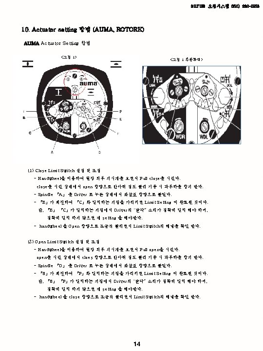
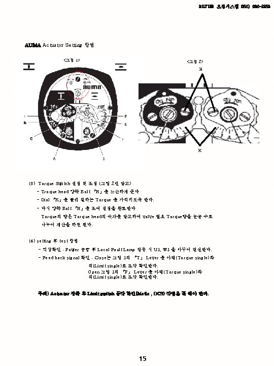
aurum 10. ACTUATOR SETTING 방법 오럼시스템 052) 222 -2358
aurum AUMA actuator의 구조 16 오럼시스템 052) 222 -2358
aurum 11. Actuator 의 구조 Matic Norm 17 오럼시스템 052) 222 -2358
aurum Norm 오럼시스템 052) 222 -2358 Indicate Control unit Hollow shaft / Worm shaft Hollow shaft Motor 의 회전력에 의해 전달되는 힘을 Worm shaft에서 hollow Shaft로 전달하여 stem 및 Gear box 를 구동하게 하는 구조 Control unit Limit , Torque switch 를 Gear를 이용하여 기계적으로 제어를 하는 구조 Motor shaft 부분에 Gear를 부착하여 worm shaft 에 동력을 전달하는 구조로 되여 있다. 18
aurum AUMA Actuator 구성도 19 오럼시스템 052) 222 -2358
aurum 오럼시스템 052) 222 -2358 AUMA Actuator 명칭 No Designation Type No. Designation Type 001. 0 Housing Sub-assy 058. 0 Whre for protective earth Sub-assy 002. 0 Bearing flange Sub-assy 061. 0 Torque switching head Sub-assy 003. 0 Hollow shaft without worm wheel Sub-assy 070. 0 Motor(VD motor incl. no. 079. 0) Sub-assy 005. 0 Worm shaft Sub-assy 079. 0 Planetary gear for motor drive (SA/SAR 16. 1 for AD 90 motor) Sub-assy 005. 1 Motor coupling 080. 0 Planetary gear for motor drive (SA/SAR 16. 1 for AD 90 motor) 005. 2 Coupling pin 155. 0 Reduction gearing Sub-assy 005. 3 Manual drive coupling 500. 0 Cover for switch compartment Sub-assy 005. 4 Pull rope 501. 0 Socket carrier (complate with sockets) Sub-assy 006. 0 Worm wheel 502. 0 Pin carrier without pins Sub-assy 009. 0 Planetary gear for manual dirve Sub-assy 503. 0 Socket for controls Sub-assy 010. 0 Retaining flange Sub-assy 504. 0 Pin for motor Sub-assy 017. 0 Torque lever Sub-assy 505. 0 Pin for controls Sub-assy 018. 0 Gear segment 506. 0 Pin for motor Sub-assy 019. 0 Crown wheel Sub-assy 507. 0 Plug cover Sub-assy 020. 0 Swing lever Sub-assy 511. 0 Screw plug Sub-assy 022. 0 Drive pinion II for torque switching Sub-assy 514. 0 Output drive form A (witchout stem nut) Sub-assy 023. 0 Output drive wheel for limit switching Sub-assy 514. 1 Axial needle roller bearing Sub-assy 024. 0 Intermediate wheel for limit switching Sub-assy 516. 1 Output dirve shaft D 024. 0 Intermediate wheel for limit switching Sub-assy 535. 1 Snap ring 025. 0 Locking plate Sub-assy 20 Sub-assy
aurum No Designation Type No. 오럼시스템 052) 222 -2358 Designation Type 535. 1 Snap ring 566. 0 Position transmitter RWG Sub-assy 539. 0 Screw plug 566. 1 Potentiometer for RWG with slip clutch Sub-assy 542. 0 Handwheel with ball handle 566. 2 Electronic board RWG Sub-assy 549. 1 Output socket B 3/B 4/E 566. 3 Wire harness for RWG Sub-assy 551. 1 Parallel key 567. 1 Slip clutch for potentiometer/RWG Sub-assy 553. 0 Mechanical position indcator Sub-assy 568. 1 Stem protection tube (without cap) 554. 0 Socket carrier with motor cable harness Sub-assy 568. 2 Cap for stem protection tube 556. 0 Potentiometer for position transmitter Sub-assy 568. 3 V-seal 556. 1 Potentiometer without slip clutch Sub-assy 569. 0 Change-over lever assy 557. 0 Heater Sub-assy 569. 1 Change-over lever 558. 0 Blinker transmitter including pins at wires (without inpulse disc and insulation plate) Sub-assy 569. 2 Notched pin 559. 0 -1 Control unit without torque switching heads and switches Sub-assy 574. 1 Radial seal output drive A for ISO flange 559. 0 -2 Control unit with magnetic limit and torque transmitter (MWG) for Non -intrusive version in combination with AUMATIC intergral controls Sub-assy 575. 1 Stem nut type A 560. 0 -1 Switch stack for direction OPEN Sub-assy S 1 Seal kit, small Set 560. 0 -2 Switch stack for direction CLOSE Sub-assy S 2 Seal kit, large set 560. 1 Switch for limit/torque switching 560. 2 Switch case Sub-assy 21
aurum 오럼시스템 052) 222 -2358 12. 각 사별 비교표 Rotork Limitorque Biffi EIM Bernard Auma Top mounted Side mounted High torque endlever High torque end-lever Low torque end-lever Handwheel Low torque end Customizable orientation No Yes (180º only) Screen only No Yes Remote control – wall bracket No No Yes Display module only Yes 1, 2&3 (*1002 confituration) 1, 2 No No No 1, 2&3 (*1002 confiturati on) Anti back drive ( NSL Geares) No No No Yes Plug and socket connector No No No Yes Large LCD Backlit display No No No Yes 3 4 3 6 2 6 No Yes Yes Yes (Reuqires Battery) No No No Yes Yes Yes (0. 5 meter) No Yes Yes No No Yes (10 meters) 6 9 5 6 8 23 Piezo sensor Springs Motor calculatio n Springs Namur Compliance (NE 107) No No No Yes Space Heater No Yes Yes No Yes Explosion Proof IEC Yes No No Yes IEC Explosion proof Gear’s Yes No No Yes Modbus Loop No Yes Yes Yes Display Colour Change on Failure No No No Yes Selector Switch Padlock included No No No Yes Manual Operation Signal Yes No Yes (with battery option) Yes Self Monitoring Yes Yes No Yes Torque Curves Display No No Yes Hand wheel position Declutchactivation SIL LED For indcation Absolute Position Encoder Incremental Position Encoder Set-up – Local Control Switches Set-up Irda Controller Set-up Bluetooth Programmable Languages Torque Measurement 23
aurum 오럼시스템 052) 222 -2358 #. Motor Technical Data 3 -Phase AC motor DC motor Standard voltages 50 Hz : 220 V, 230 V, 240 V, 380 V, 400 V, 415 V, 500 V 60 Hz : 208 V, 230 V, 440 V, 460 V, 480 V, 575 V 50 Hz : 220 V ~ 240 V 60 Hz : 110 V ~ 120 V, 220 V, 110 V, 60 V, 48 V, 24 V Permissible variations ± 10% Motor data Refer to data sheets Design/mounting IM B 9 acc. To IEC 34 -7 Type of motor Squirrel cage Enclosure protection NEMA 4 X , IP 67 NEMA 6 , IP 68 (OPTION) Type of cooling Self-cooling / surface cooling (IC 40 according to IEC 34 -6) Insulation class F according to NEMA MG 1 , tropicalized Electrical connection for motor Up to SA 16. 1 (up to 7. 5 kw) : AUAM plug/socket connector at multi-turn actuator SA 25. 1 and Larger : Terminals at multi-turn actuator Starting Direct on line Type of duty S 2 -15 min, S 2 -30 min, S 425%, S 4 -50% ED relative on time or S 5 Direction of rotation Clockwise and counter-clockwise (reversing) Motor protection 3 themoswitches (standard) or 3 PTC thermistors (option) IM B 14 according to IEC 34 -7 Squirrel cage NEMA 4 , IP 65 ~ IP 68 24 DC-rotor IP 55 IP 67/68(OPTION) AUMA plug/socket connector at multiturn actuator Motor terminal box S 2 -10 min or S 4 -25% ED relative on- time S 2 -15 min 2 thermoswitches
aurum 오럼시스템 052) 222 -2358 #. Motor Technical Data Output speeds for multi-turn actuators for open-close duty Max Torque Size SA 3 -Phase AC motor S 2 -15 min / S 2 -30 min 1 -Phase AC motor S 2 -10 min DC motor S 2 -15 min [ft lb] [Nm] 50 Hz[rpm ] 60 Hz[rpm ] [rpm] 07. 1 20 30 4 – 180 4. 8 – 216 4 – 180 07. 5 45 60 4 – 180 4. 8 – 216 4 – 180 10. 1 88 120 4 – 180 4. 8 – 216 4 – 180 14. 1 185 250 4 – 180 4. 8 – 216 8 – 45 9. 6 – 54 4 – 180 14. 5 370 500 4 – 180 4. 8 – 216 8 – 22 9. 6 – 26 4 – 45 16. 1 740 1000 4 – 180 4. 8 – 216 25. 1 1500 2000 4 – 90 4. 8 – 108 30. 1 2960 4000 4 – 90 4. 8 – 108 35. 1 5900 8000 4 – 45 4. 8 – 54 40. 1 11800 16000 4 – 32 4. 8 – 38 48. 1 23600 32000 4 – 16 4. 8 – 19 4 – 22 Output speeds for multi-turn actuators for Modulating duty Size SAR Max Torque 3 -Phase AC motor S 2 -15 min / S 2 -30 min 1 -Phase AC motor S 2 -10 min [ft lb] [Nm] 50 Hz[rpm] 60 Hz[rpm] 07. 1 10 15 4 – 45 4. 8 – 54 07. 5 20 30 4 – 45 4. 8 – 54 10. 1 45 60 4 – 45 4. 8 – 54 4 – 11 4. 8 – 13 14. 1 88 120 4 – 45 4. 8 – 54 8 - 11 9. 6 – 13 14. 5 150 200 4 – 45 4. 8 – 54 16. 1 300 4 – 45 4. 8 – 54 25. 1 600 800 4 – 11 4. 8 – 13 30. 1 1200 1600 4 – 11 4. 8 - 13 25
aurum 오럼시스템 052) 222 -2358 #. Flange Dimensions ISO 5210/1 MOUNTING FLANGE TYPE ΦD 1 P. C. D D 2 ΦD 3 F-05 35 50 65 F-07 55 70 90 H MAX. Bolt Thread Tap Dp Min M 6 ¼”-20 UNC 9 M 8 5/16” 18 UNC 12 3 F-10 70 102 125 M 10 3/8”-16 UNC 15 F-12 85 125 150 M 12 ½”-13 UNC 18 F-14 100 140 175 M 16 5/8”-11 UNC 24 F-16 130 165 210 M 20 ¾”-10 UNC 30 F-25 200 254 300 M 16 5/8”-11 UNC 24 4 No. of screws 4 5 F-30 298 350 M 20 ¾”-10 UNC 30 F-35 260 356 415 M 30 1”-8 UNC 45 F-40 300 406 475 M 36 1 ¼”-7 UNC 54 F-48 370 483 560 M 36 1 ¼”-7 UNC 54 12 F-60 470 603 686 M 36 1 ¼”-7 UNC 54 20 8 8 26