Attitude and Orbit Control System AOCS CO1 COI2
 CO-1 COI-2")
Attitude and Orbit Control System (AOCS) CO-1 COI-2

Satellite Subsystems
 • Telemetry, Tracking,")
Satellite Subsystems Space Segment • Attitude and Orbit Control System (AOCS) • Telemetry, Tracking, Command monitoring (TTC&M) • Power system • Communication Subsystems/Transpond ers • Satellite Antennas Earth Segment • • Transmitter Receiver Earth station Antenna Tracking subsystem

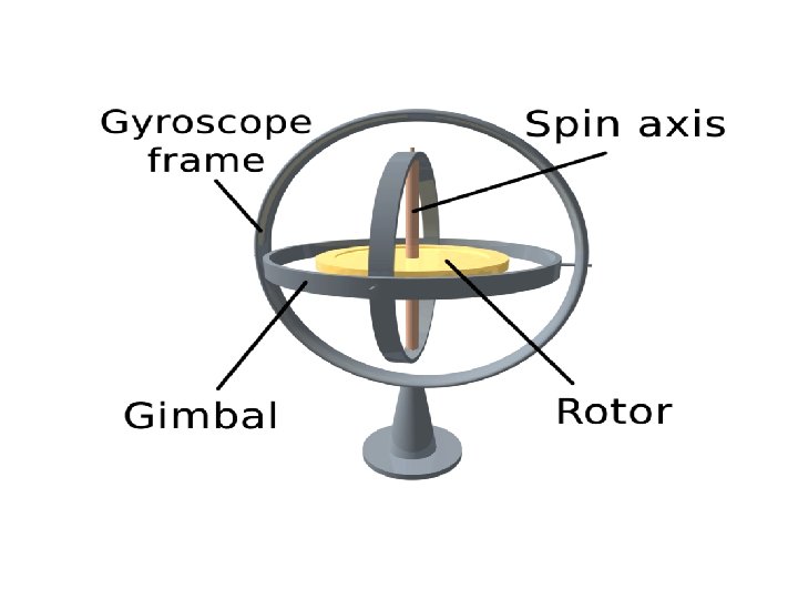
Attitude: Introduction Ø The Attitude of a Satellite is its position in Space -its Orientation, measured by the angles it makes with the Earth. Ø Determines which way its cameras/Antennas are facing, and the angle the satellite makes with the object it is orbiting. Ø To stabilize a satellite, it must have a system that keeps it moving evenly through its orbit. Ø Satellites use a Spinning or Gyroscopic motion to keep them stable.

Importance • A satellite's measurements and pictures will be inaccurate and fuzzy if it is not stabilized. • Satellite's orbit is more likely to decay - slowly change course either toward the Earth or out into space - if it is not stabilized • In stabilizing a satellite, the direction that the satellites' instruments and solar panels are facing is also important (Power consumption)
 • Attitude and Orbit of satellite must be")
Attitude and Orbit Control System (AOCS) • Attitude and Orbit of satellite must be controlled to point the satellite antenna (narrow beam type) towards the Earth. • Mainly for GEO satellites as the earth station Antennas are fixed and may face signal loss.
and Moon (Due")
Factors for Orbital Perturbation q Gravitational field of Sun (Due to size)and Moon (Due to closeness) q Asymmetry of Earth’s Gravitational field due to Non-sphericity, Non-circularity , Nonuniform density q Solar Radiation Pressure q Variation in earth’s Magnetic field q Atmospheric drag
 A. Attitude Control Subsystem Gas Jets or Inertial")
Attitude and Orbit Control System (AOCS) A. Attitude Control Subsystem Gas Jets or Inertial devices (Control Attitude/Orientation of Satellite) B. Orbit Control Subsystem Rocket motors/Maneuvers (Correct Orbit of Satellite)
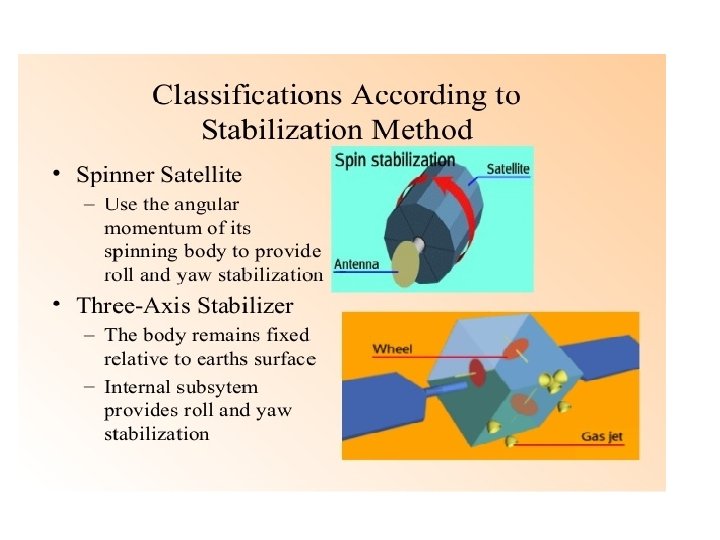

A. Attitude Control Subsystem • Spinning the Satellite üEntire satellite including its antenna spins (satellite as a whole acting as a Gyroscope) üTo point the antenna all-time, despun/counter-rotation of antenna is required. • Three axes method ü Stabilization by one or more Momentum Wheels (internal Gyroscope) and small thruster jets or rockets

Spinning the Satellite Three Axis Method
 Spinning the Satellite q Body of the satellite rotates around its spin axis")
(1) Spinning the Satellite q Body of the satellite rotates around its spin axis to create a Gyroscopic force. q Spinning can be achieved using Rods with coils of wire around them. q As current is passed through the Rods, it creates a magnetic fields around the wires q When the Rod's magnetic field interacts with Earth's magnetic field, the rod begins to spin. q Such Rods in 3 -opposing directions allows the satellite to spin stably in all three axes (up, down, and out). q Due to this, the satellite will point in the same direction. q Such satellites are called Spinners
 Spinning the Satellite § Spinner contains a Cylindrical Drum (Covered with Solar cells)")
(1) Spinning the Satellite § Spinner contains a Cylindrical Drum (Covered with Solar cells) § Power Systems and Rockets inside the Drum. § Communication Subsystem on the top of the drum driven by an Electric Motor. § Satellite body rotates up to 30 -100 rpm. § The direction of motor is opposite to the rotation of Satellite body to point the antennas towards the Earth.

Spin Axis Communication Subsystem Electric Motor Solar Cell Power System and Rockets
 Spinning the Satellite")
(1) Spinning the Satellite
 Spinning the Satellite ADVANTAGES v Satellite's attitude is very stable as the whole")
(1) Spinning the Satellite ADVANTAGES v Satellite's attitude is very stable as the whole body acts as a Gyroscope v Requires only a small amount of power to pass electric current through the three rods, much less total power than using thrusters for attitude control v An interesting way to map the Earth's magnetic field DISADVANTAGES ü Solar panels cannot collect solar power all the time as they spin. ü Instruments can only take measurements in one direction each rotation
 Three Axes Method q. Uses one or more Momentum Wheels to stabilize the")
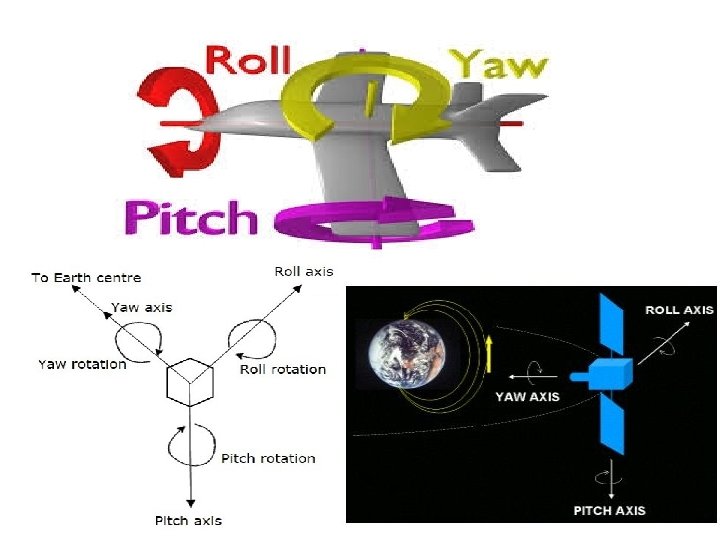
(2) Three Axes Method q. Uses one or more Momentum Wheels to stabilize the satellite q. Internal Gyroscope can be used as a sensor to tell the satellite when its attitude (direction) is changing. i. Roll axis: Direction in which Satellite moves in the Orbital plane. ii. Yaw axis: Direction towards Earth. iii. Pitch axis: Direction perpendicular to Orbital plane
 Three Axes Method ADVANTAGES v. Orientation by three axes is controlled without rotating")
(2) Three Axes Method ADVANTAGES v. Orientation by three axes is controlled without rotating the Satellite’s main body. v. Satellite as a whole can point stably in one direction v. Solar panels can always point at the Sun v. Instruments can always point at their target DISADVANTAGES ü Thrusters are heavy and use up lots of power
 Attitude Control System • These three axis are defined by considering the satellite’s")
(A) Attitude Control System • These three axis are defined by considering the satellite’s position as reference. These three axes define the ideal attitude/orientation of satellite. • Let XR, YR and ZR are the roll axis, yaw axis and pitch axis respectively. Let X, Y and Z are another set of Cartesian axes. This set of three axis provides the information about actual orientation of the satellite with respect to reference axes. If there is a change in attitude of the satellite, then the angles between the respective axes will be changed. • In this method, each axis contains two gas jets. They will provide the rotation in both directions of the three axes. • The first gas jet will be operated for some period of time, when there is a requirement of satellite’s motion in a particular axis direction. • The second gas jet will be operated for same period of time, when the satellite reaches to the desired position. So, the second gas jet will stop the motion of satellite in that axis direction.
 Orbit Control Subsystem • Orbit control subsystem is useful in order to bring")
(B) Orbit Control Subsystem • Orbit control subsystem is useful in order to bring the satellite into its correct orbit, whenever the satellite gets deviated from its orbit. • The Telemetry, Tracking, Command monitoring (TTCM) subsystem present at earth station monitors the position of satellite. • If there is any change in satellite orbit, then it sends a signal regarding the correction to Orbit control subsystem. • Orbit control subsystem resolve the issue by using Spacecraft Rocket motors/maneuvers to correct the inplane change (longitudinal drift) and out-of-plane changes (inclination changes).
- Slides: 22