
ATS Training Outline n What is a Transfer




- Slides: 48
ATS Training Outline n What is a Transfer Switch? â n What Makes A Transfer Switch Reliable? â Segmented Contacts, Arc Gaps Transfer Switch Mechanism Analysis â Control Panel Evolution â n Application Issues â â n Motor Load transfer (Inphase, DTTS, etc. ) Switching The Neutral in Ground Fault Systems What Are The Codes & Standards â 4 Application UL 1008, CSA, IEC 60947 -6, NFPA 700, 701, 702 We Keep Your Power On
ATS Training Outline n Automatic Transfer Switches & Derivatives â Automatic Transfer Switch Closed Transition Switch â Automatic Transfer/ Bypass Switch â Static Transfer Switch & Hybrid Static Transfer n Communication Products n â â 4 Remote Annunciators PC Based Software Systems We Keep Your Power On
Why Are Transfer Switches Needed? n To assure continuity of vital electrical power for essential loads: â Prevent accidents, theft, panic, loss of revenue Comply with codes & standards â Comply with government regulations â n 4 Whenever two or more sources of power are utilized for essential electrical loads. We Keep Your Power On
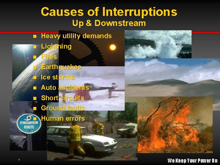
Causes of Interruptions Up & Downstream Heavy utility demands n Lightning n Fires n Earthquakes n Ice storms n Auto accidents n Short circuits n Ground faults n n 4 Human errors We Keep Your Power On
Impact of ATS Failures n Panic & Confusion â Loss of lights (10 second rule) â Elevators, escalators, electric doors Traffic control â Communications â n Loss of Life â Hospital equipment - â 4 Life support, Operating Rooms & ER Radar equipment We Keep Your Power On
Impact of ATS Failures n Loss of revenue â â n â Fire alarms, fire pumps Intrusion alarms Loss of information â â 4 Toll gates Refrigeration Loss of property â n Cash registers Assembly lines Computers Data Centers We Keep Your Power On
Where Are Transfer Switches Used? Hospitals & other health care facilities n Telecommunications & other utilities n Banks & computer facilities n Industrial buildings & WWTPs n Office buildings n Airports n Government & military installations n Police & security systems n n 4 Bridge & tunnels 16 We Keep Your Power On
Automatic Transfer Switch Design Considerations 4 We Keep Your Power On
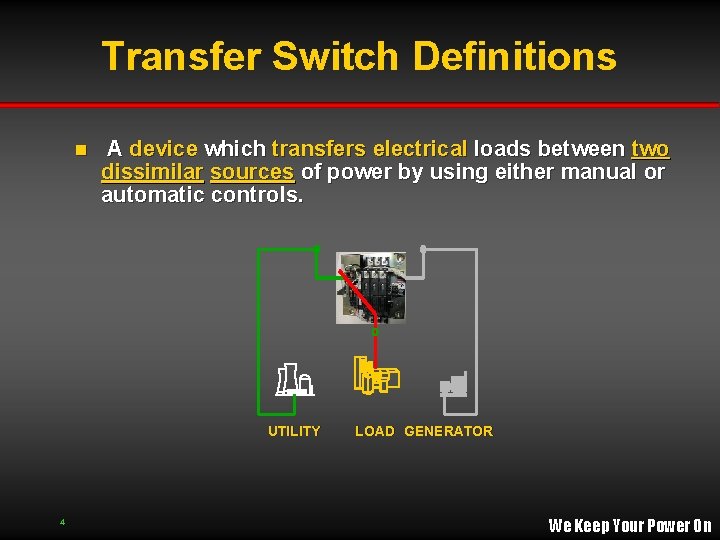
Transfer Switch Definitions n A device which transfers electrical loads between two dissimilar sources of power by using either manual or automatic controls. UTILITY 4 LOAD GENERATOR We Keep Your Power On
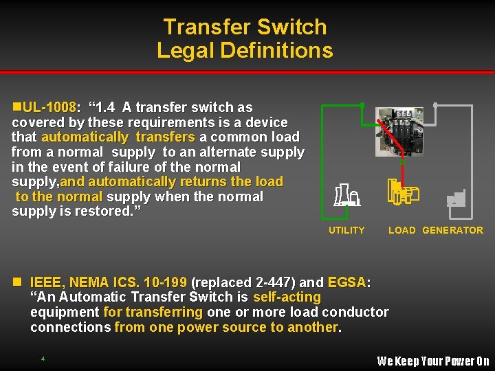
Transfer Switch Legal Definitions n. UL-1008: “ 1. 4 A transfer switch as covered by these requirements is a device that automatically transfers a common load from a normal supply to an alternate supply in the event of failure of the normal supply, and automatically returns the load to the normal supply when the normal supply is restored. ” UTILITY LOAD GENERATOR n IEEE, NEMA ICS. 10 -199 (replaced 2 -447) and EGSA: “An Automatic Transfer Switch is self-acting equipment for transferring one or more load conductor connections from one power source to another. 4 We Keep Your Power On
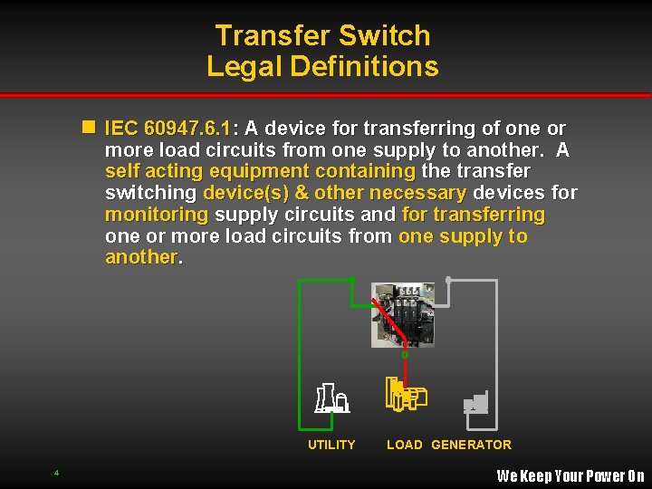
Transfer Switch Legal Definitions n IEC 60947. 6. 1: A device for transferring of one or more load circuits from one supply to another. A self acting equipment containing the transfer switching device(s) & other necessary devices for monitoring supply circuits and for transferring one or more load circuits from one supply to another. UTILITY 4 LOAD GENERATOR We Keep Your Power On
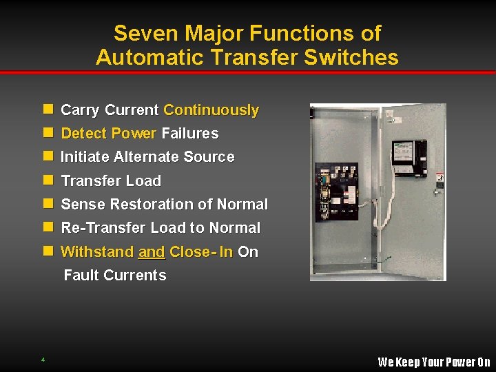
Seven Major Functions of Automatic Transfer Switches n n n n Carry Current Continuously Detect Power Failures Initiate Alternate Source Transfer Load Sense Restoration of Normal Re-Transfer Load to Normal Withstand Close- In On Fault Currents 4 We Keep Your Power On
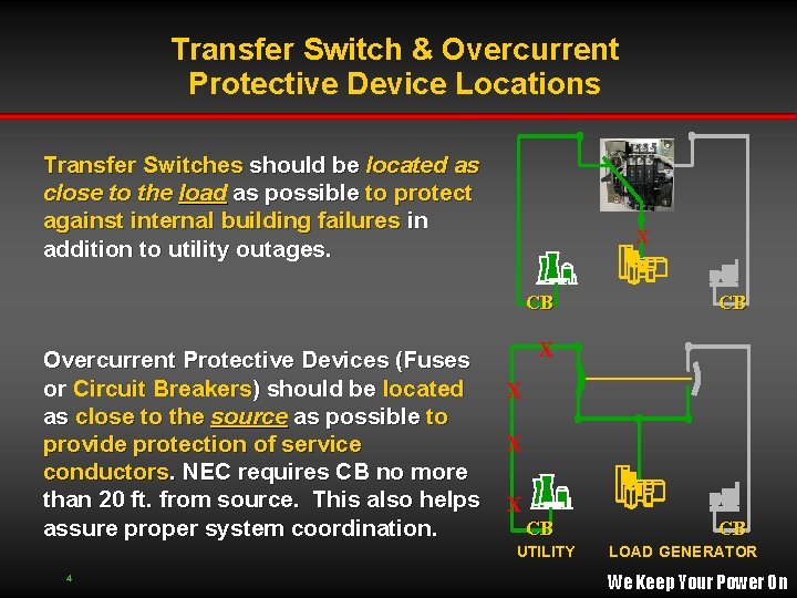
Transfer Switch & Overcurrent Protective Device Locations Transfer Switches should be located as close to the load as possible to protect against internal building failures in addition to utility outages. X CB Overcurrent Protective Devices (Fuses or Circuit Breakers) should be located as close to the source as possible to provide protection of service conductors. NEC requires CB no more than 20 ft. from source. This also helps assure proper system coordination. X X CB UTILITY 4 CB CB LOAD GENERATOR We Keep Your Power On
Basic Transfer Switch Types n Automatic transfer switches operate automatically upon source failure or voltage reduction. n Non-automatic transfer switches must be manually initiated and can be either electrically or mechanically operated. For manual or auto-start engine - generators Ø Switches with selector/ toggle switches that disable automatic transfer or retransfer must me labeled nonautomatic per UL 1008 standard Ø 4 We Keep Your Power On
Transfer Switch Types Non - Automatic Transfer Switches n Electrically Operated â â n No or Basic Sensing Full Sensing Electrically Operated Automatic Transfer Switches n Most Transfer Switches Are Normal Seeking Selective Normal n Non - Selective Normal n 4 We Keep Your Power On
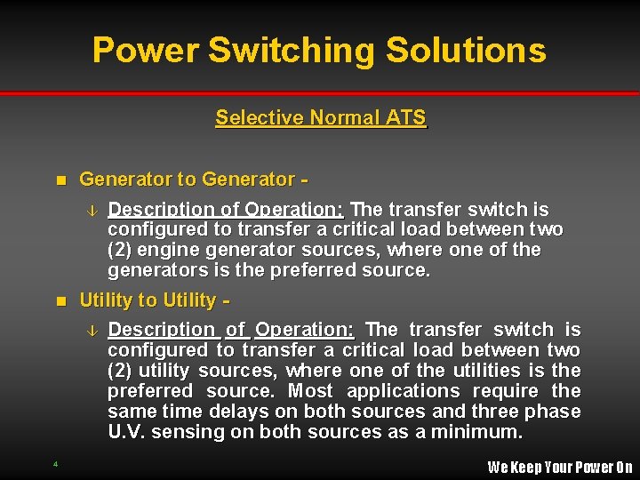
Power Switching Solutions Selective Normal ATS n Definition: A transfer switch whose control circuitry is configured for “Normal Seeking Operation”. In other words, it always wants to be connected to a preferred source. The user can choose which service is the normal/preferred source. n Typical Configurations â Utility to Generator Standard/Conventional type ATS â Utility to Utility - â Generator 4 to Generator We Keep Your Power On
Power Switching Solutions Selective Normal ATS Generator to Generator â Description of Operation: The transfer switch is configured to transfer a critical load between two (2) engine generator sources, where one of the generators is the preferred source. n Utility to Utility n â 4 Description of Operation: The transfer switch is configured to transfer a critical load between two (2) utility sources, where one of the utilities is the preferred source. Most applications require the same time delays on both sources and three phase U. V. sensing on both sources as a minimum. We Keep Your Power On
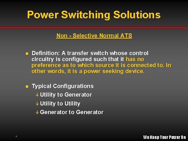
Power Switching Solutions Non - Selective Normal ATS n Definition: A transfer switch whose control circuitry is configured such that it has no preference as to which source it is connected to. In other words, it is a power seeking device. n Typical Configurations â Utility to Generator â Utility to Utility â Generator to Generator 4 We Keep Your Power On
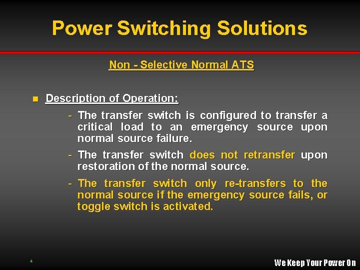
Power Switching Solutions Non - Selective Normal ATS n 4 Description of Operation: - The transfer switch is configured to transfer a critical load to an emergency source upon normal source failure. - The transfer switch does not retransfer upon restoration of the normal source. - The transfer switch only re-transfers to the normal source if the emergency source fails, or toggle switch is activated. We Keep Your Power On
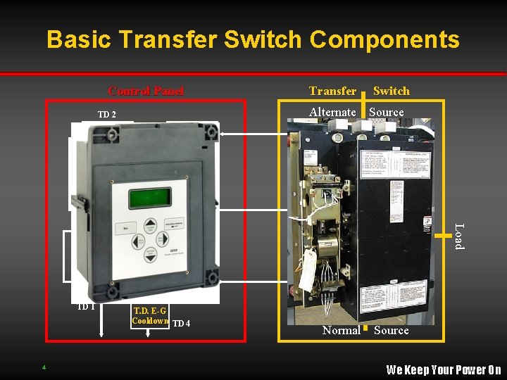
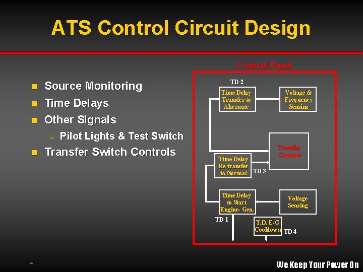
Basic Transfer Switch Components Control Panel Time Delay Transfer to Alternate Voltage & Frequency Sensing 4 Transfer Controls Transfer Operator Load Time Delay Re-transfer to Normal TD 3 TD 1 Switch Alternate Source TD 2 Time Delay to Start Engine- Gen. Transfer Voltage Sensing T. D. E-G Cooldown TD 4 Normal Source We Keep Your Power On
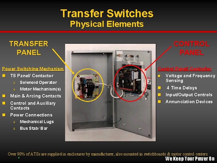
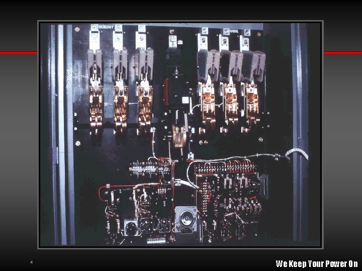
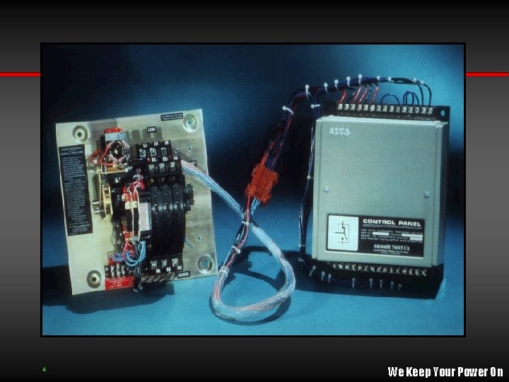
Transfer Switches Physical Elements TRANSFER PANEL CONTROL PANEL Power Switching Mechanism Control Panel/ Controller n TS Panel/ Contactor n â Solenoid Operator â Motor Mechanism(s) n Main & Arcing Contacts n Control and Auxiliary Voltage and Frequency Sensing n 4 Time Delays n Input/Output Controls n Annunciation Devices Contacts n Power Connections â Mechanical Lugs â Bus Stab/ Bar Over 90% of ATSs are supplied in enclosures by manufacturer, also mounted in switchboards & motor control centers. 4 We Keep Your Power On
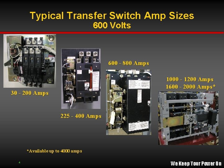
Typical Transfer Switch Amp Sizes 600 Volts 600 - 800 Amps 1000 - 1200 Amps 1600 - 2000 Amps* 30 - 200 Amps 225 - 400 Amps *Available up to 4000 amps 4 We Keep Your Power On
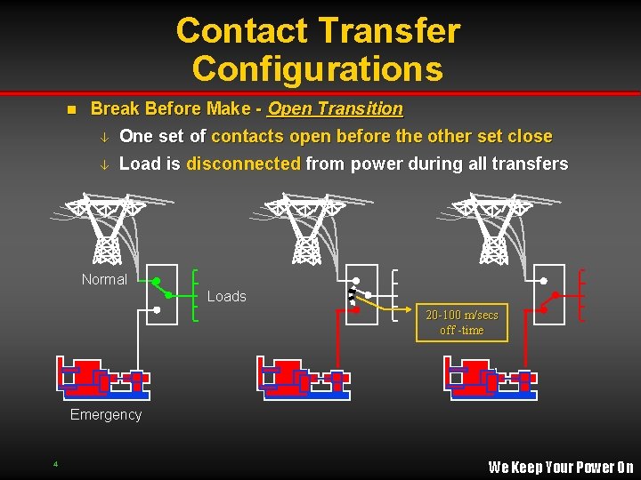
Contact Transfer Configurations n Break Before Make - Open Transition â One set of contacts open before the other set close â Load is disconnected from power during all transfers Normal Loads 20 -100 m/secs off -time Emergency 4 We Keep Your Power On
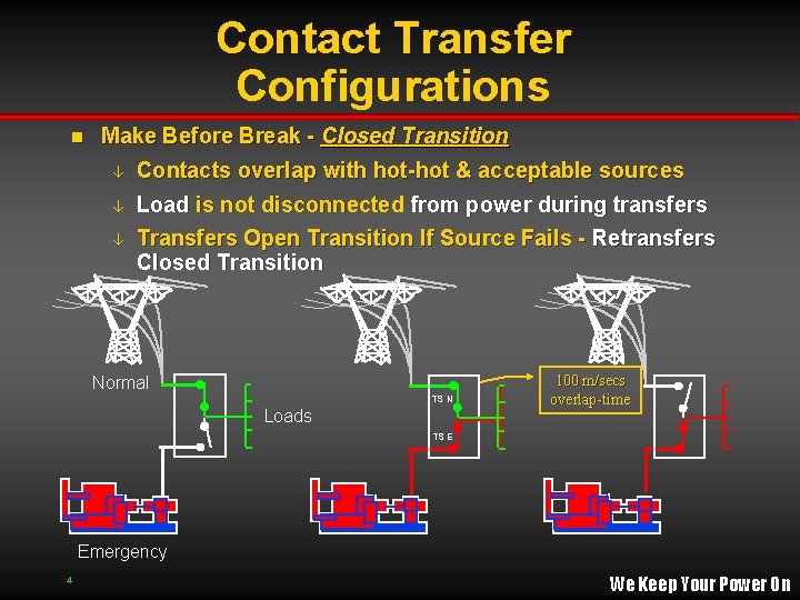
Contact Transfer Configurations n Make Before Break - Closed Transition â Contacts overlap with hot-hot & acceptable sources â â Load is not disconnected from power during transfers Transfers Open Transition If Source Fails - Retransfers Closed Transition Normal TS N Loads 100 m/secs overlap-time TS E Emergency 4 We Keep Your Power On
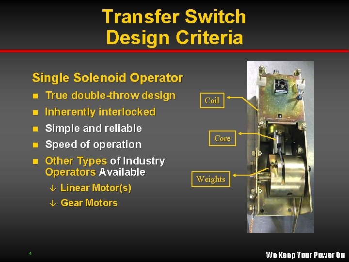
Transfer Switch Design Criteria Single Solenoid Operator True double-throw design n Inherently interlocked n Simple and reliable n Speed of operation n n Other Types of Industry Operators Available Linear Motor(s) â Gear Motors â 4 Coil Core Weights We Keep Your Power On
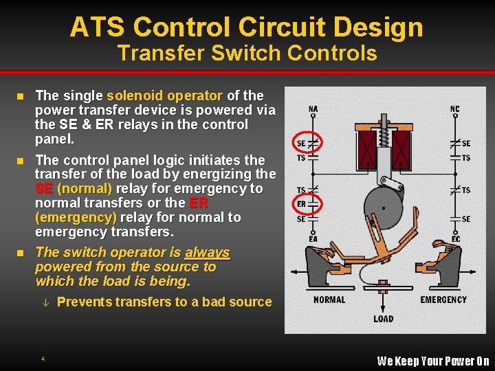
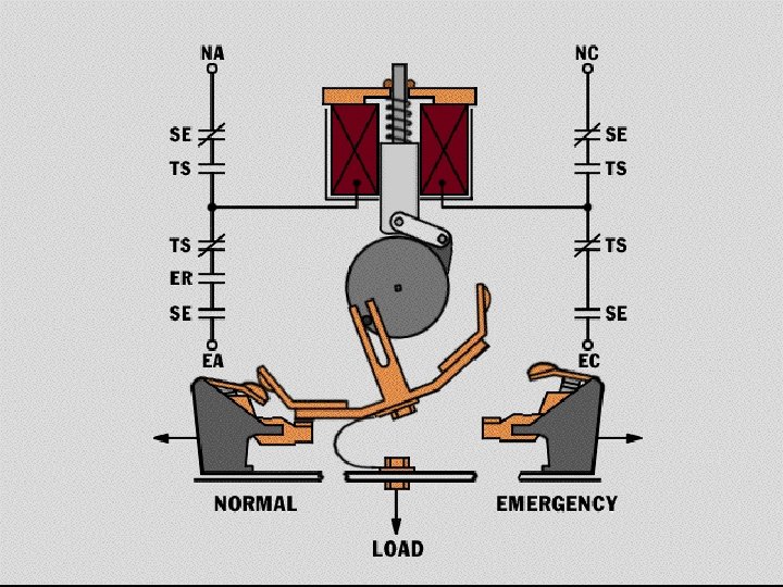
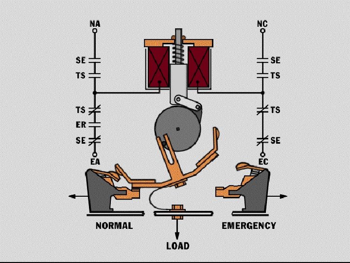
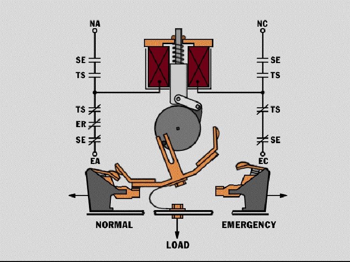
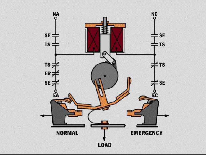
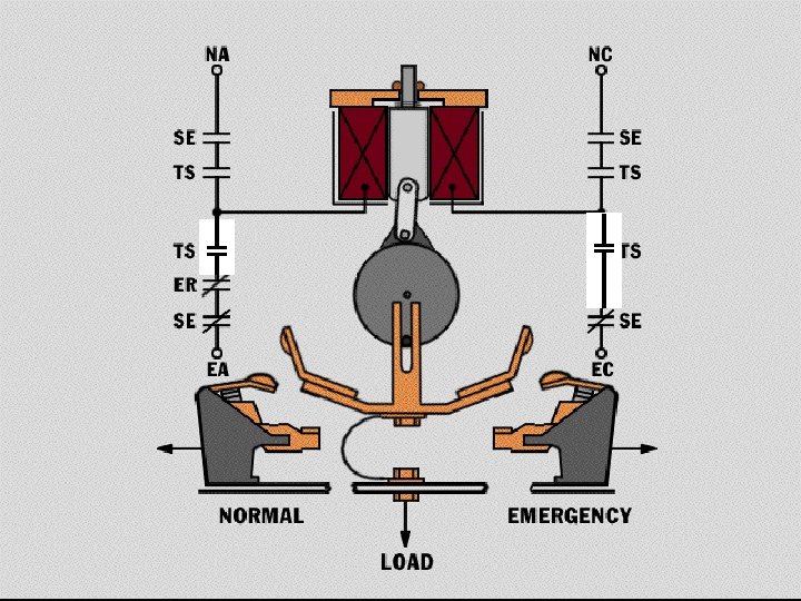
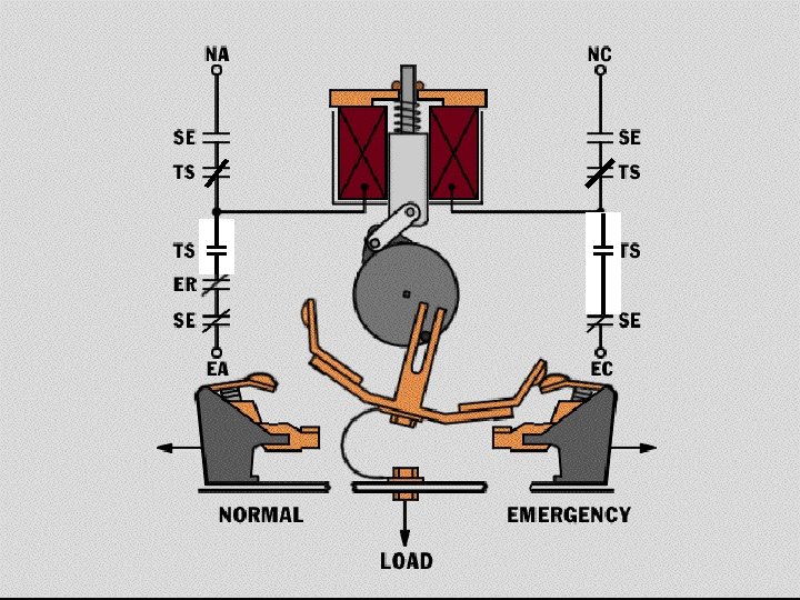
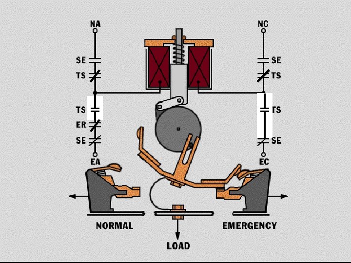
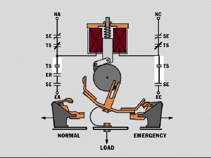
ATS Control Circuit Design Transfer Switch Controls The single solenoid operator of the power transfer device is powered via the SE & ER relays in the control panel. n The control panel logic initiates the transfer of the load by energizing the SE (normal) relay for emergency to normal transfers or the ER (emergency) relay for normal to emergency transfers. n The switch operator is always powered from the source to which the load is being. n â 4 Prevents transfers to a bad source We Keep Your Power On
4 We Keep Your Power On
4 We Keep Your Power On
4 We Keep Your Power On
4 We Keep Your Power On
4 We Keep Your Power On
4 We Keep Your Power On
4 We Keep Your Power On
4 We Keep Your Power On
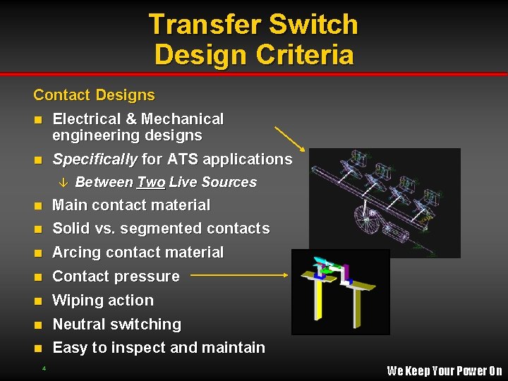
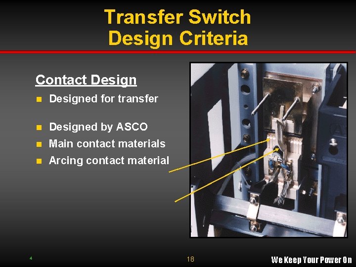
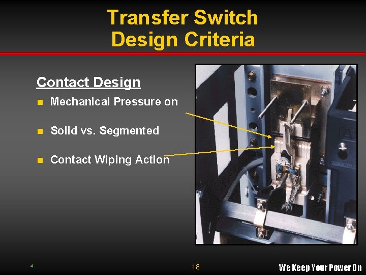
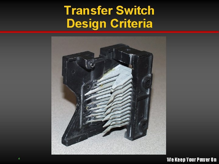
Transfer Switch Design Criteria Contact Designs n Electrical & Mechanical engineering designs n Specifically for ATS applications â Between Two Live Sources Main contact material n Solid vs. segmented contacts n Arcing contact material n Contact pressure n Wiping action n Neutral switching n n 4 Easy to inspect and maintain We Keep Your Power On
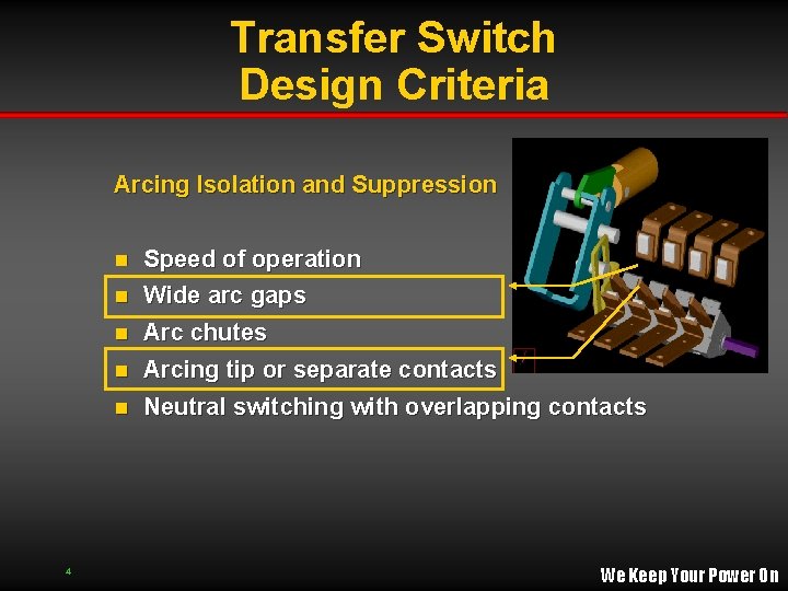
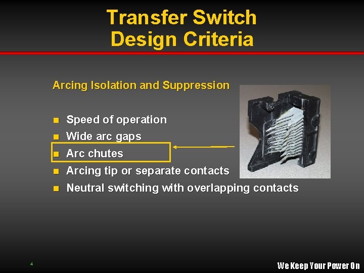
Transfer Switch Design Criteria Arcing Isolation and Suppression Speed of operation n Wide arc gaps n Arc chutes n Arcing tip or separate contacts n n 4 Neutral switching with overlapping contacts We Keep Your Power On
Transfer Switch Design Criteria Contact Design 4 n Designed for transfer n Designed by ASCO n Main contact materials n Arcing contact material switch applications 18 We Keep Your Power On
Transfer Switch Design Criteria Contact Design 4 n Mechanical Pressure on Main Contacts n Solid vs. Segmented Contacts n Contact Wiping Action 18 We Keep Your Power On
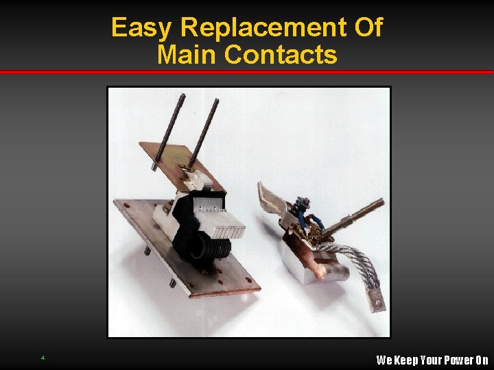
Easy Replacement Of Main Contacts 4 We Keep Your Power On
Transfer Switch Design Criteria Arcing Isolation and Suppression Speed of operation n Wide arc gaps n Arc chutes n Arcing tip or separate contacts n n 4 Neutral switching with overlapping contacts We Keep Your Power On
Transfer Switch Design Criteria 4 We Keep Your Power On
ATS Control Circuit Design Control Panel Source Monitoring n Time Delays n n Time Delay Transfer to Alternate Pilot Lights & Test Switch Transfer Switch Controls Time Delay Re-transfer to Normal TD 3 Time Delay to Start Engine- Gen. TD 1 4 Voltage & Frequency Sensing Other Signals â n TD 2 Transfer Controls Voltage Sensing T. D. E-G Cooldown TD 4 We Keep Your Power On
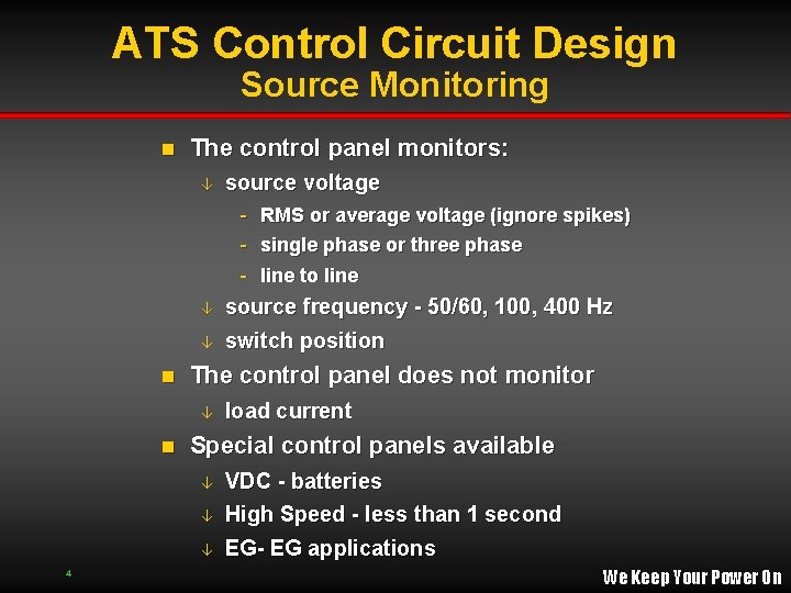
ATS Control Circuit Design Source Monitoring n The control panel monitors: â source voltage - RMS or average voltage (ignore spikes) - single phase or three phase - line to line â â n The control panel does not monitor â n load current Special control panels available â VDC - batteries High Speed - less than 1 second â EG- EG applications â 4 source frequency - 50/60, 100, 400 Hz switch position We Keep Your Power On
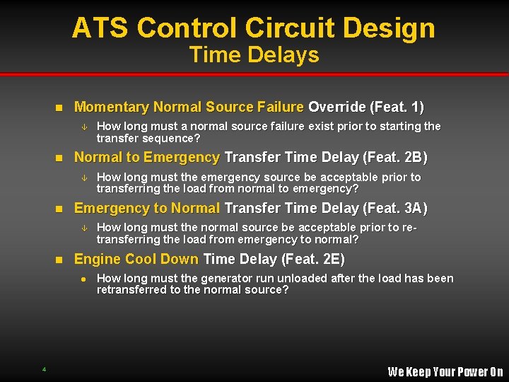
ATS Control Circuit Design Time Delays n Momentary Normal Source Failure Override (Feat. 1) â n Normal to Emergency Transfer Time Delay (Feat. 2 B) â n How long must the normal source be acceptable prior to retransferring the load from emergency to normal? Engine Cool Down Time Delay (Feat. 2 E) l 4 How long must the emergency source be acceptable prior to transferring the load from normal to emergency? Emergency to Normal Transfer Time Delay (Feat. 3 A) â n How long must a normal source failure exist prior to starting the transfer sequence? How long must the generator run unloaded after the load has been retransferred to the normal source? We Keep Your Power On
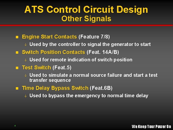
ATS Control Circuit Design Other Signals n Engine Start Contacts (Feature 7/8) â n Switch Position Contacts (Feat. 14 A/B) â n Used to simulate a normal source failure and start a test transfer sequence Time Delay Bypass Switch (Feat. 6 B) â 4 Used for remote indication of switch position Test Switch (Feat. 5) â n Used by the controller to signal the generator to start Used to bypass the emergency to normal time delay We Keep Your Power On
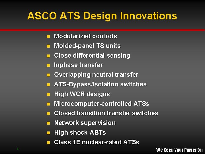
ASCO ATS Design Innovations Modularized controls n Molded-panel TS units n Close differential sensing n Inphase transfer n Overlapping neutral transfer n ATS-Bypass/Isolation switches n High WCR designs n Microcomputer-controlled ATSs n Closed transition transfer switches n Network supervision n High shock ABTs n Class 1 E nuclear-rated ATSs n 4 We Keep Your Power On
4 We Keep Your Power On
4 We Keep Your Power On