
ATLAS Pixel Detector PST Design Update PST CDR
- Slides: 28
ATLAS Pixel Detector PST Design Update PST CDR october 2001 October 2001 Pixel Week N. Hartman LBNL
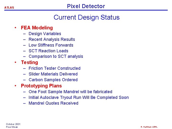
Pixel Detector ATLAS Current Design Status • FEA Modeling – – – Design Variables Recent Analysis Results Low Stiffness Forwards SCT Reaction Loads Comparison to SCT analysis • Testing – Friction Tester Constructed – Slider Materials Delivered – Carbon Samples Ordered • Prototyping Plans – One Foot Sample Mandrel will be fabricated – Initial Autoclave Tryout Run Will Be Completed Soon – Mandrel Quotes Received October 2001 Pixel Week N. Hartman LBNL
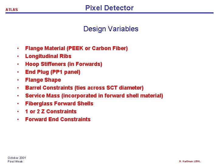
Pixel Detector ATLAS Design Variables • • • Flange Material (PEEK or Carbon Fiber) Longitudinal Ribs Hoop Stiffeners (in Forwards) End Plug (PP 1 panel) Flange Shape Barrel Constraints (ties across SCT diameter) Service Mass (incorporated in forward shell material) Fiberglass Forward Shells 1 or 2 Z Constraints Forward End Constraints October 2001 Pixel Week N. Hartman LBNL
ATLAS Pixel Detector PST Model October 2001 Pixel Week N. Hartman LBNL
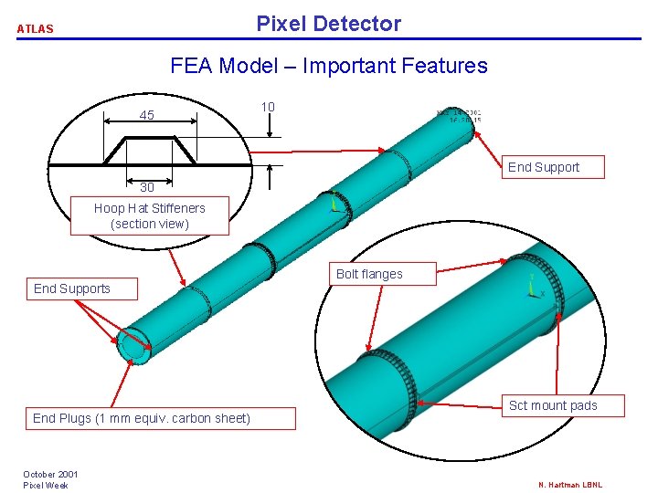
Pixel Detector ATLAS FEA Model – Important Features 45 10 End Support 30 Hoop Hat Stiffeners (section view) Bolt flanges End Supports End Plugs (1 mm equiv. carbon sheet) October 2001 Pixel Week Sct mount pads N. Hartman LBNL
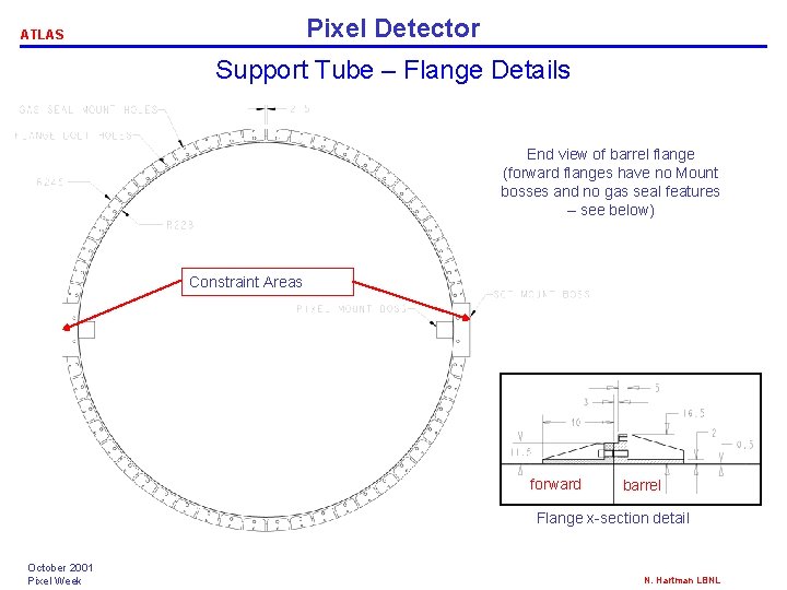
Pixel Detector ATLAS Support Tube – Flange Details End view of barrel flange (forward flanges have no Mount bosses and no gas seal features – see below) Constraint Areas forward barrel Flange x-section detail October 2001 Pixel Week N. Hartman LBNL
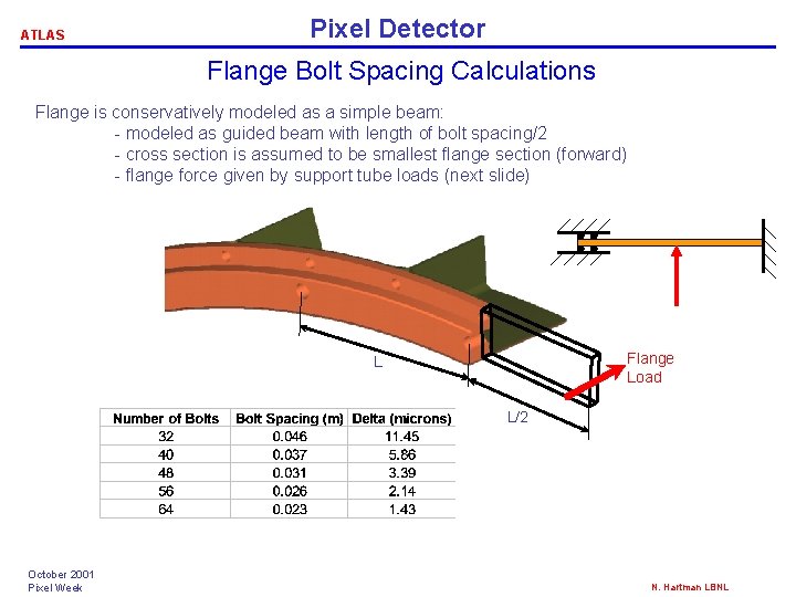
ATLAS Pixel Detector Flange Bolt Spacing Calculations Flange is conservatively modeled as a simple beam: - modeled as guided beam with length of bolt spacing/2 - cross section is assumed to be smallest flange section (forward) - flange force given by support tube loads (next slide) Flange Load L L/2 October 2001 Pixel Week N. Hartman LBNL
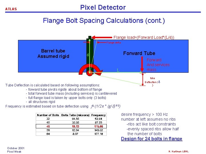
Pixel Detector ATLAS Flange Bolt Spacing Calculations (cont. ) Flange load=(Forward Load*(L/d)) Flange delta Barrel tube Assumed rigid Forward Tube d L Forward And services mass tube Tube Deflection is calculated based on following assumptions: - forward tube pivots rigidly about bottom of flange - total forward tube mass (including services) is cantilevered - full flange load is taken by upper bolts only (3 bolts) - all structures rigid Frequency is estimated based on tube deflection using f=(1/2 p * (g/d)1/2) Deflection ( d ) desire frequency > 100 Hz number at left assumes no ribs -ribs act like bolt constraints -evenly spaced ribs allow half the number of bolts Design for 24 bolts in flange October 2001 Pixel Week N. Hartman LBNL
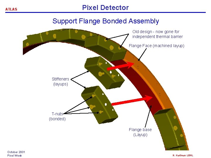
Pixel Detector ATLAS Support Flange Bonded Assembly Old design - now gone for independent thermal barrier Flange Face (machined layup) Stiffeners (layups) T-nuts (bonded) Flange base (Layup) October 2001 Pixel Week N. Hartman LBNL
ATLAS Pixel Detector PST Boundary Conditions October 2001 Pixel Week N. Hartman LBNL
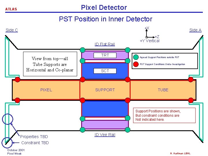
Pixel Detector ATLAS PST Position in Inner Detector +X Side C ID Flat Rail View from top—all Tube Supports are Horizontal and Co-planar PIXEL TRT Side A +Z +Y Vertical Agreed Support Positions outside PST Support Conditions Under Investigation SCT SUPPORT TUBE Support Positions are shown, But constraint conditions are Not indicated here. Properties TBD Constraint TBD October 2001 Pixel Week ID Vee Rail N. Hartman LBNL
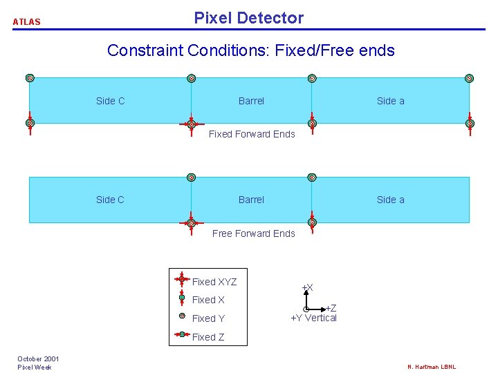
Pixel Detector ATLAS Constraint Conditions: Fixed/Free ends Side C Barrel Side a Fixed Forward Ends Side C Barrel Side a Free Forward Ends Fixed XYZ Fixed X Fixed Y +X +Z +Y Vertical Fixed Z October 2001 Pixel Week N. Hartman LBNL
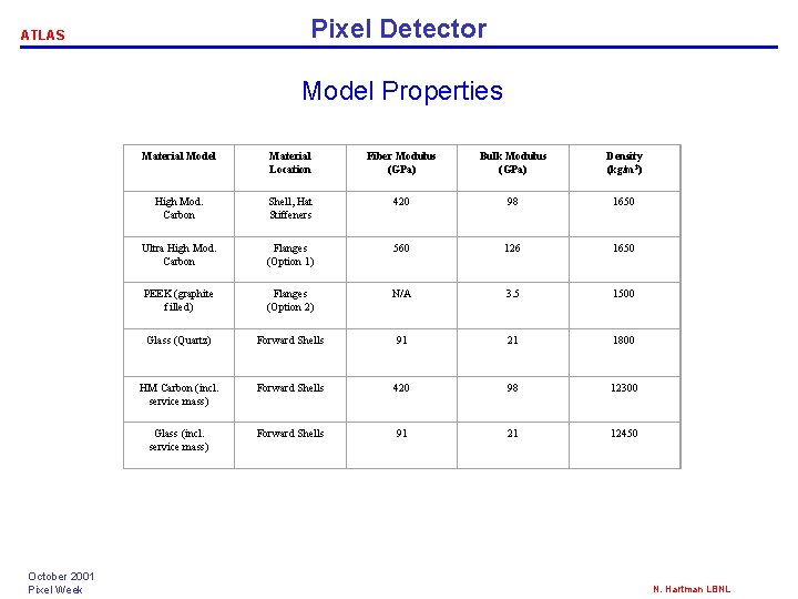
Pixel Detector ATLAS Model Properties Material Model Material Location Fiber Modulus (GPa) Bulk Modulus (GPa) Density (kg/m 3) High Mod. Carbon Shell, Hat Stiffeners 420 98 1650 Ultra High Mod. Carbon Flanges (Option 1) 560 126 1650 PEEK (graphite filled) Flanges (Option 2) N/A 3. 5 1500 Glass (Quartz) Forward Shells 91 21 1800 October 2001 Pixel Week HM Carbon (incl. service mass) Forward Shells 420 98 12300 Glass (incl. service mass) Forward Shells 91 21 12450 N. Hartman LBNL
ATLAS Pixel Detector PST Analyses October 2001 Pixel Week N. Hartman LBNL
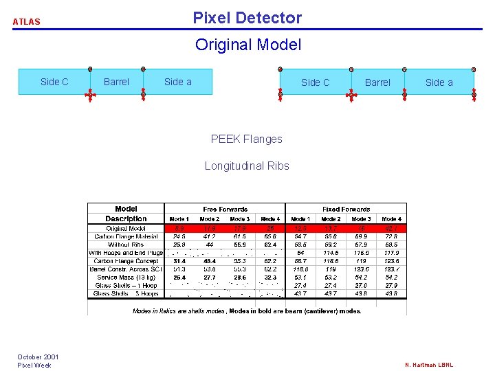
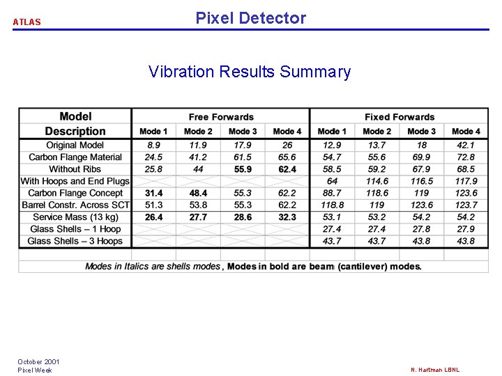
Pixel Detector ATLAS Original Model Side C Barrel Side a PEEK Flanges Longitudinal Ribs October 2001 Pixel Week N. Hartman LBNL
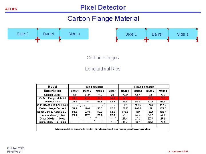
Pixel Detector ATLAS Carbon Flange Material Side C Barrel Side a Carbon Flanges Longitudinal Ribs October 2001 Pixel Week N. Hartman LBNL
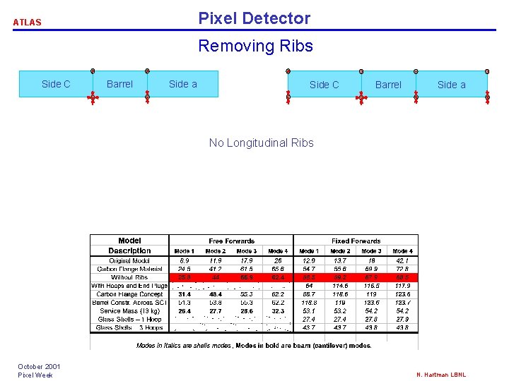
Pixel Detector ATLAS Removing Ribs Side C Barrel Side a No Longitudinal Ribs October 2001 Pixel Week N. Hartman LBNL
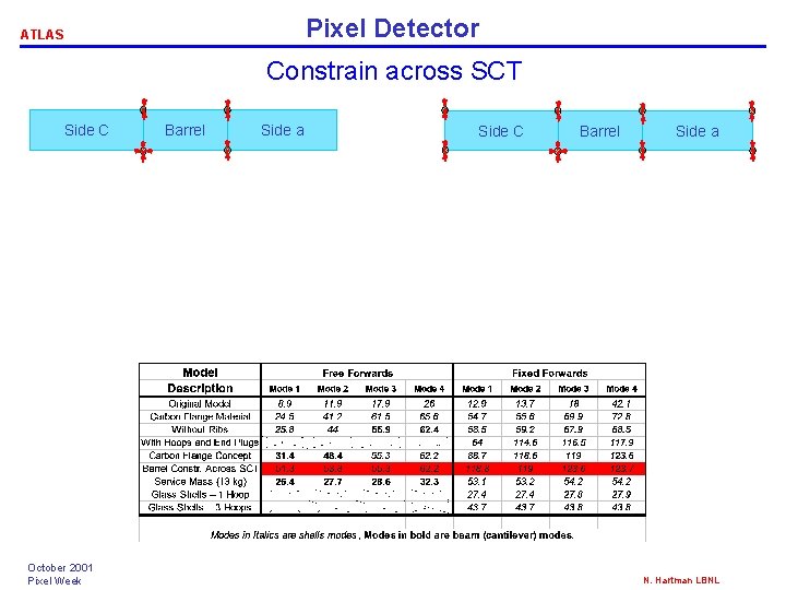
Pixel Detector ATLAS Constrain across SCT Side C October 2001 Pixel Week Barrel Side a Side C Barrel Side a N. Hartman LBNL
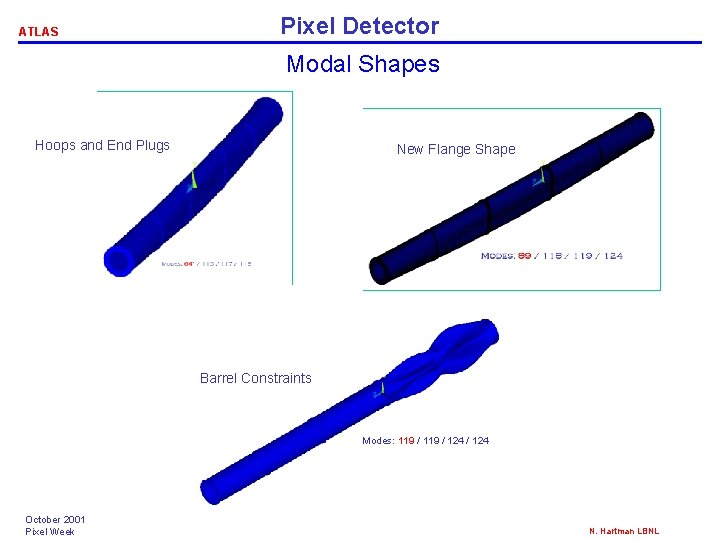
ATLAS Pixel Detector Modal Shapes Hoops and End Plugs New Flange Shape Barrel Constraints Modes: 119 / 124 October 2001 Pixel Week N. Hartman LBNL
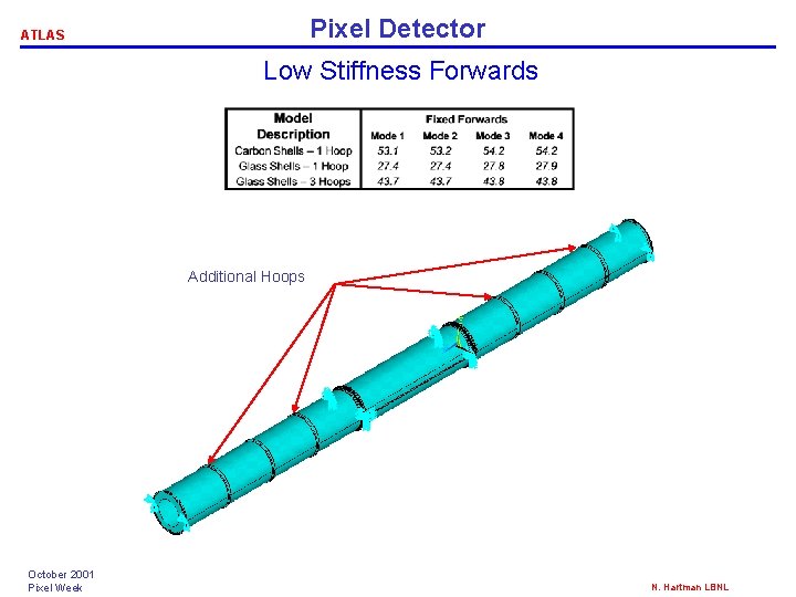
Pixel Detector ATLAS Low Stiffness Forwards Additional Hoops October 2001 Pixel Week N. Hartman LBNL
ATLAS Pixel Detector Vibration Results Summary October 2001 Pixel Week N. Hartman LBNL
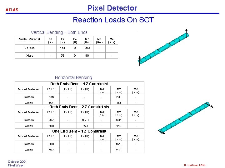
Pixel Detector ATLAS Reaction Loads On SCT Vertical Bending – Both Ends Model Material FX (N) FY (N) FZ (N) MX (Nm) MY (Nm) MZ (Nm) Carbon - 151 0 253 - - Glass - 53 0 89 - - Horizontal Bending Both Ends Bent – 1 Z Constraint Model Material FX (N) FY (N) FZ (N) MX (Nm) MY (Nm) MZ (Nm) Carbon 146 - - - 233 - Glass 52 - - - 83 - Model Material FX (N) FY (N) FZ (N) MX (Nm) MY (Nm) MZ (Nm) Carbon 297 - 1870 - 536 - Glass 108 - 468 - 110 - Both Ends Bent – 2 Z Constraints One End Bent – 1 Z Constraint Model Material FX (N) FY (N) FZ (N) MX (Nm) MY (Nm) MZ (Nm) Carbon 390 - - - 623 - Glass 137 - - - 218 - October 2001 Pixel Week N. Hartman LBNL
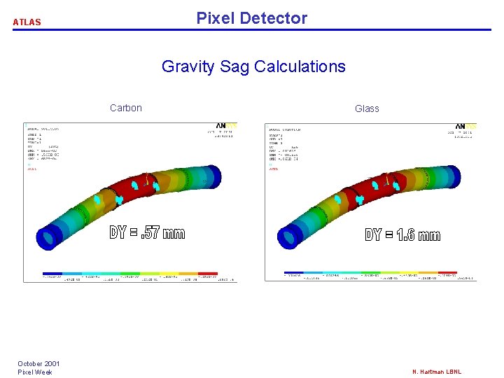
Pixel Detector ATLAS Gravity Sag Calculations Carbon October 2001 Pixel Week Glass N. Hartman LBNL
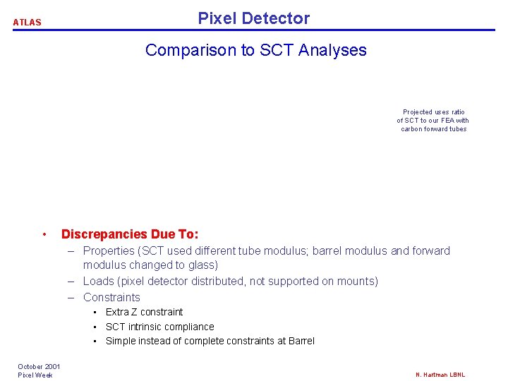
Pixel Detector ATLAS Comparison to SCT Analyses Projected uses ratio of SCT to our FEA with carbon forward tubes • Discrepancies Due To: – Properties (SCT used different tube modulus; barrel modulus and forward modulus changed to glass) – Loads (pixel detector distributed, not supported on mounts) – Constraints • Extra Z constraint • SCT intrinsic compliance • Simple instead of complete constraints at Barrel October 2001 Pixel Week N. Hartman LBNL
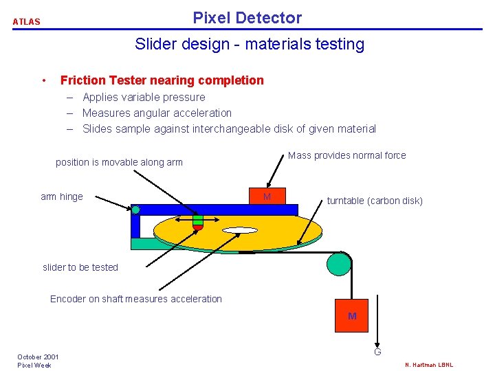
Pixel Detector ATLAS Slider design - materials testing • Friction Tester nearing completion – Applies variable pressure – Measures angular acceleration – Slides sample against interchangeable disk of given material Mass provides normal force position is movable along arm hinge M turntable (carbon disk) slider to be tested Encoder on shaft measures acceleration M October 2001 Pixel Week G N. Hartman LBNL
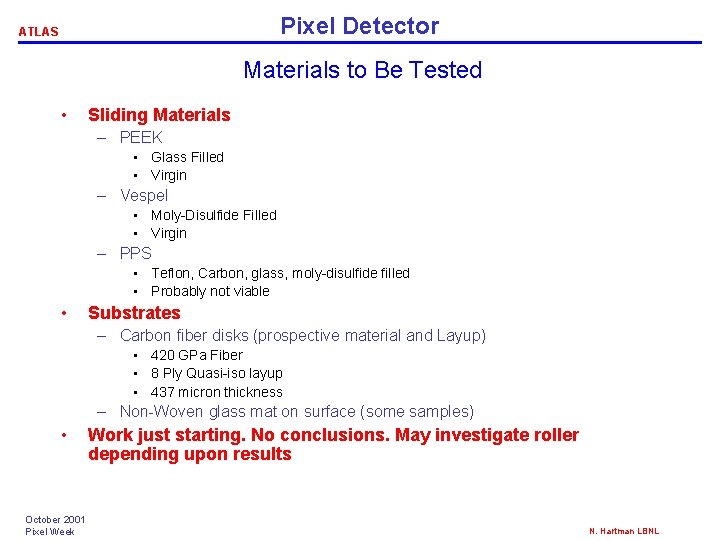
Pixel Detector ATLAS Materials to Be Tested • Sliding Materials – PEEK • Glass Filled • Virgin – Vespel • Moly-Disulfide Filled • Virgin – PPS • Teflon, Carbon, glass, moly-disulfide filled • Probably not viable • Substrates – Carbon fiber disks (prospective material and Layup) • 420 GPa Fiber • 8 Ply Quasi-iso layup • 437 micron thickness – Non-Woven glass mat on surface (some samples) • October 2001 Pixel Week Work just starting. No conclusions. May investigate roller depending upon results N. Hartman LBNL
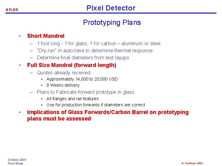
Pixel Detector ATLAS Prototyping Plans • Short Mandrel – 1 foot long - 1 for glass, 1 for carbon – aluminum or steel – “Dry-run” in autoclave to determine thermal response – Determine final diameters from test layups • Full Size Mandrel (forward length) – Quotes already received • Approximately 14, 000 to 20, 000 USD • 8 Weeks delivery – Plans to Fabricate forward prototype in glass • All flanges and rail features • Use for production forwards if diameters are correct • October 2001 Pixel Week Implications of Glass Forwards/Carbon Barrel on prototyping plans must be assessed N. Hartman LBNL
Pixel Detector ATLAS Plans For Near Future • Import SCT Model into current analyses – Double check SCT loads – ascertain acceptability – Determine pixel stability with reduced stiffnesses • Begin detailed design of flanges and tubes • Fabricate sample tube sections (1 foot lengths) • Analyze mounts/end constraints/service interactions – Eric Anderssen’s presentation October 2001 Pixel Week N. Hartman LBNL