
ATHERMAL LENS MOUNT DESIGN A tutorial on the

- Slides: 21
ATHERMAL LENS MOUNT DESIGN A tutorial on the use of ZEMAX and Solidworks in athermal lens mount design By James Champagne OPTI 521 – Optomechanical Engineering Fall 2010
Overview � � � Goal is to design a lens mount to compensate defocus caused by temperature changes Space Environment (Assume ΔT = 60 C) Remote Sensing Infrared Optical System ZEMAX Solidworks
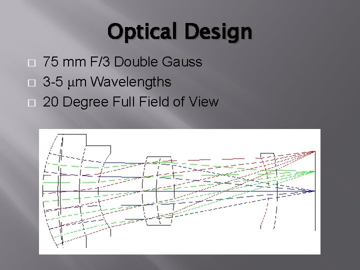
Optical Design � � � 75 mm F/3 Double Gauss 3 -5 μm Wavelengths 20 Degree Full Field of View
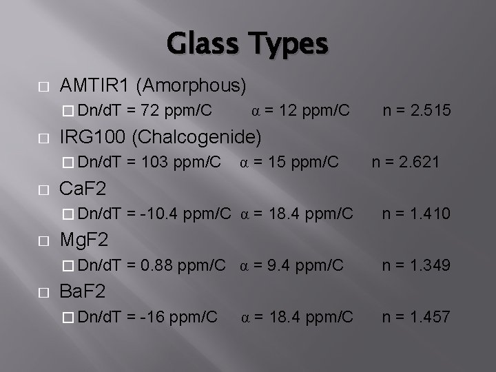
Glass Types � AMTIR 1 (Amorphous) � Dn/d. T = 72 ppm/C � α = 12 ppm/C n = 2. 515 IRG 100 (Chalcogenide) � Dn/d. T = 103 ppm/C α = 15 ppm/C n = 2. 621 � Ca. F 2 � Dn/d. T = -10. 4 ppm/C � α = 18. 4 ppm/C n = 1. 410 Mg. F 2 � Dn/d. T = 0. 88 ppm/C α = 9. 4 ppm/C � n = 1. 349 Ba. F 2 � Dn/d. T = -16 ppm/C α = 18. 4 ppm/C n = 1. 457
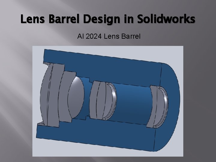
Lens Barrel Design in Solidworks Al 2024 Lens Barrel
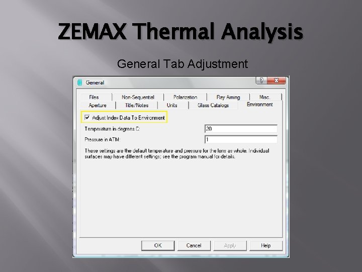
ZEMAX Thermal Analysis General Tab Adjustment
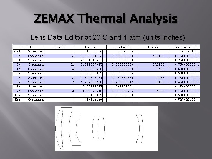
ZEMAX Thermal Analysis Lens Data Editor at 20 C and 1 atm (units: inches)
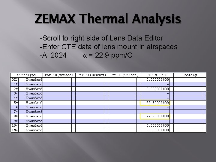
ZEMAX Thermal Analysis -Scroll to right side of Lens Data Editor -Enter CTE data of lens mount in airspaces -Al 2024 α = 22. 9 ppm/C
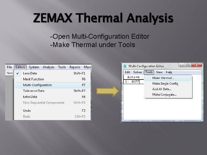
ZEMAX Thermal Analysis -Open Multi-Configuration Editor -Make Thermal under Tools
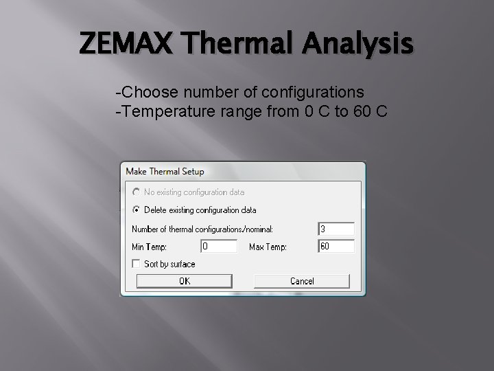
ZEMAX Thermal Analysis -Choose number of configurations -Temperature range from 0 C to 60 C
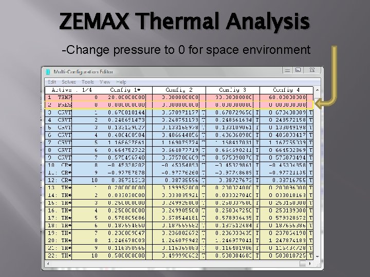
ZEMAX Thermal Analysis -Change pressure to 0 for space environment
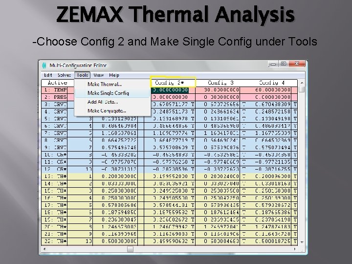
ZEMAX Thermal Analysis -Choose Config 2 and Make Single Config under Tools
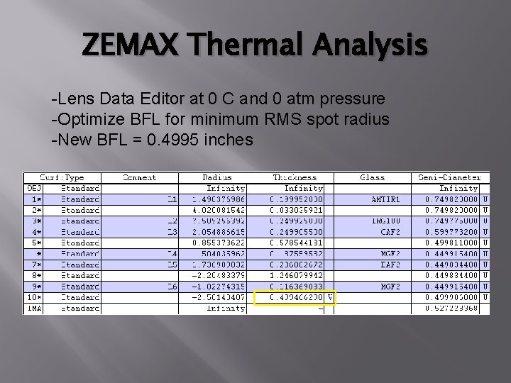
ZEMAX Thermal Analysis -Lens Data Editor at 0 C and 0 atm pressure -Optimize BFL for minimum RMS spot radius -New BFL = 0. 4995 inches
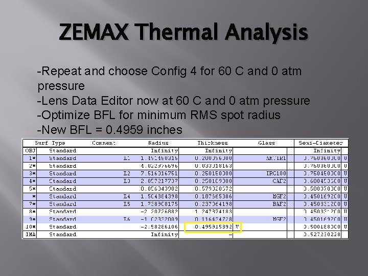
ZEMAX Thermal Analysis -Repeat and choose Config 4 for 60 C and 0 atm pressure -Lens Data Editor now at 60 C and 0 atm pressure -Optimize BFL for minimum RMS spot radius -New BFL = 0. 4959 inches
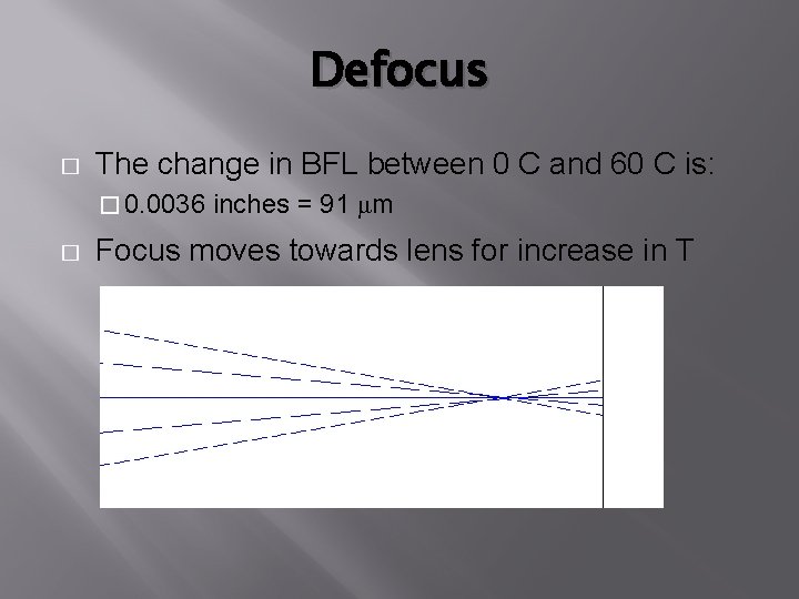
Defocus � The change in BFL between 0 C and 60 C is: � 0. 0036 inches = 91 μm � Focus moves towards lens for increase in T
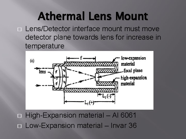
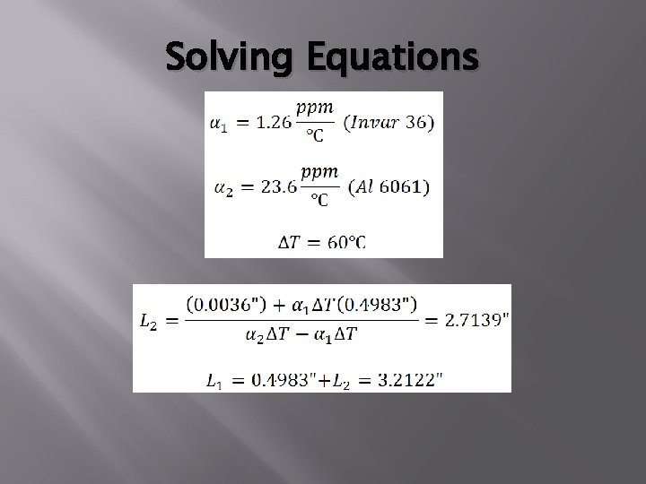
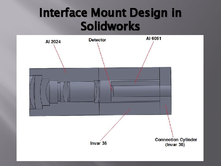
Athermal Lens Mount � Lens/Detector interface mount must move detector plane towards lens for increase in temperature � High-Expansion material – Al 6061 Low-Expansion material – Invar 36 �
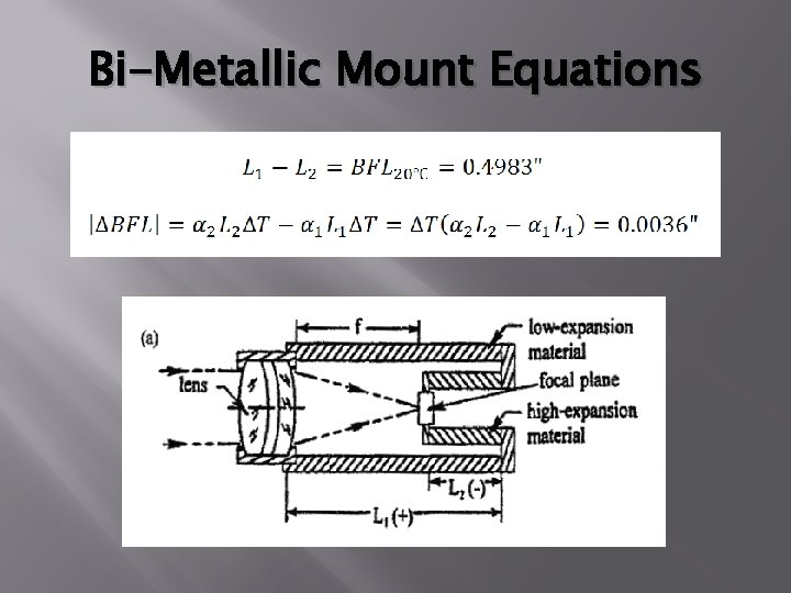
Bi-Metallic Mount Equations
Solving Equations
Interface Mount Design in Solidworks
Conclusion � Bi-metallic lens mount to compensate defocus Infrared optical system in space environment � Warnings � � dn/d. T and α not constant over large T � Check data input of ZEMAX
References � Friedman, I. , “Thermo-optical analysis of two long-focallength aerial reconnaissance lenses, ” Opt. Eng. 20, 1981: 161. � Vukobratovich, D, Introduction To Opto-Mechanical Design, Raytheon Systems Co. , Tucson, AZ. � Yoder, P. R. , Jr. , Mounting Optics in Optical Instruments, SPIE Press, Bellingham, WA, 2008. � Zemax Corporations. Zemax Optical Design User’s Manual. Chapter 19: Thermal Analysis (April 2010). � Zemax Knowledge Base. 2010. http: //www. zemax. com/kb/categories/Thermal-Analysis/