
ASYNCHRONOUS TRANSFER MODE Presenters Shahid Iqbal Haris Tariq
ASYNCHRONOUS TRANSFER MODE Presenters: Shahid Iqbal & Haris Tariq
WHAT IS ATM? � ATM is a cell-switching and multiplexing technology that combines the benefits of circuit switching (guaranteed capacity and constant transmission delay) with those of packet switching (flexibility and efficiency for intermittent traffic)
Major Advantages �Bandwidth Efficiency �Scalability �Transparency �Network Flexibility
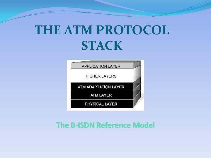
THE ATM PROTOCOL STACK The B-ISDN Reference Model
THE ATM PROTOCOL STACK �A 3 stage process o Segmentation of user data into cells o Transfer of cells through the network o Reconstruction of the original information at the receiving end
The ATM Adaptation layer (AAL) �Divides higher level data streams into segments �These segments are more compatible with the requirements of the ATM Layer �The AAL process depends on the type of traffic being transmitted
Types of traffic 5 Classes of Traffic Class A: Constant Bit Rate (CBR) �Connection-oriented �Required timing relationship between source and destination [constant bit-rate video] Class B: Variable Bit Rate (VBR) �Connection-oriented �Required timing relationship between source and destination [packet-video, voice]
Types of traffic Class C: Variable Bit Rate (VBR) � Connection-oriented � No timing relationship required between source and destination [Bursty data traffic] Class D: Variable Bit Rate (VBR) �Connectionless �No timing relationship required between source and destination [Bursty datagram traffic]
Types of traffic � Class X: User defined
The AAL Process �Divided into two sub layers: o The convergence sub layer (CS) o The segmentation and reassembly sub layer (SAR)
The convergence Sub Layer (CS) �Divides the application data stream into rational, fixed length protocol data units (PDUs) �Length of PDU depends on the nature of the traffic being passed (such as 64 Kbytes for Class D traffic) �Appends header and trailer to the CS payload
The SAR Sub Layer �Divides CS-PDUs into small segments ranging from 44 to 48 bytes in length depending on the type of traffic being transmitted � To form SAR-PDU header and trailer information is added to the basic payload segment
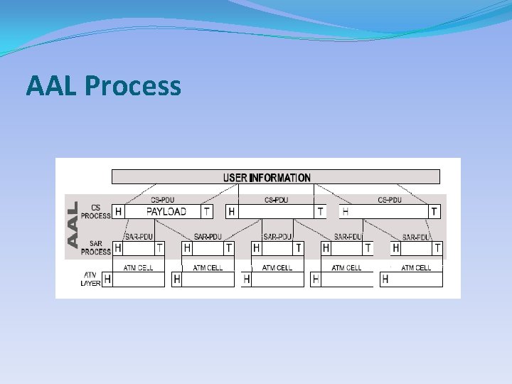
AAL Process
The ATM Layer �The heart of the ATM communication process �Packages data, received from the AAL into cells �The ATM layer operates between adjacent network nodes
Physical Layer �Defines the various transmission medium used for the transmission of the ATM cell �Divided into two parts: o The Physical Medium Dependent (PMD) Sub layer o The Transmission Convergence(TC) Sub layer
The PMD Sub Layer �Associated with a given media type and transmission speed �Deals with the actual transfer of information bits between adjacent nodes of the network �Concerned with specific characteristics of a particular transmission technology
The TC Sub Layer �Independent of the underlying physical media �Provides necessary framing and convergence operations required to fit the ATM cells into the physical transport media �Calculates and inserts the header error control information into the HEC field of the ATM cell header; and, before passing a recovered cell to the ATM layer at the receiving end, checks the received HEC field and discards the cell if an error is indicated
The ATM Protocol Data Unit : The Cell �The basic unit of ATM information transfer � 53 -byte in length �A 5 -byte header and a 48 -byte payload field
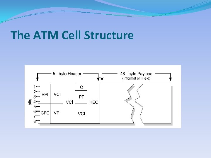
The ATM Cell Structure
The ATM Cell Fields GFC(Generic Flow control) � The last four bits of byte -1 form the generic flow control �Used to control the flow of traffic across the User. Network Interface (UNI) VPI/VCI �This three-byte field makes the ATM address �First byte contains virtual path identifier (VPI) �Next two bytes contain the virtual channel identifier (VCI)
The ATM Cell Fields PT(Payload Type) �Differentiates between user data and control messages �Indicates if a cell has experienced congestion CLP(Cell Loss Priority) �The first bit of byte-4 �Cells with a CLP set to “ 1” are subject to discard prior to cells for which the CLP is “ 0” during periods of network congestion
The ATM Cell Fields HEC(Header Error Control) PAYLOAD Field �The final byte of the ATM �The remaining 48 bytes cell header of the ATM Cell are reserved for the data �Detects errors in the cell inserted by the AAL header but not the Payload �provides protection against miss-routing of ATM cells due to addressing errors
ATM TOPOLOGY �Defines how the various network components and user terminal devices are interconnected �Interfaces are divided into two groups o User-to-network interface (UNI) o Network-to-network or node interface (NNI)
The UNI �Three variations in UNI o Public UNI o Private UNI o Residential UNI
The NNI �Three versions of the NNI o Public NNI o Private NNI(PNNI) o Broadband Inter-Carrier Interface (B-ICI)
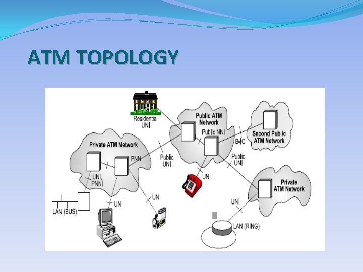
ATM TOPOLOGY
THE ATM COMMUNICATIONS PROCESS �Based on a simple and fast transport relay mechanism �Call connection, termination, addressing, sequencing, and payload error control are handled at the transmitting and receiving ends

Association between User and Network Functions
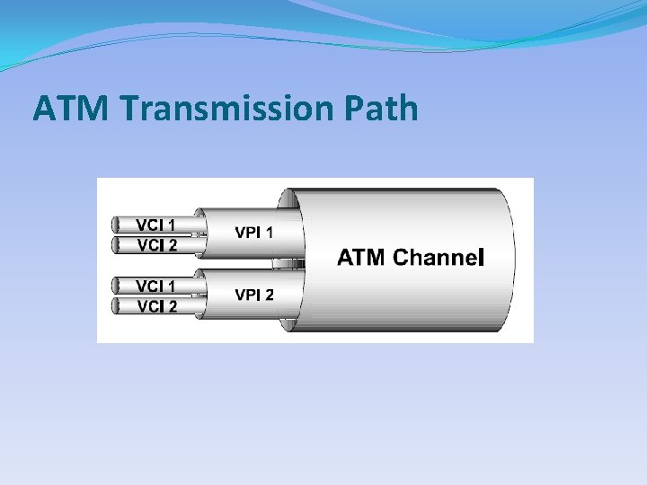
ATM Networking �Connection-oriented service �Establishes connections between adjacent Layer 2 ATM entities �Uses virtual channels and virtual paths to establish end-to-end virtual circuit connections
ATM Transmission Path �Virtual Channel (VC) �Virtual Path (VP) �Virtual Circuit Connection (VCC)
ATM Transmission Path
ATM Switching �ATM switches operate very differently from analog or digital switches �ATM switches use self-routing procedures �A self-routing switch relies on information contained in the VPI/VCI fields of the cell �The switch adds a temporary routing header or “tag” to the cell
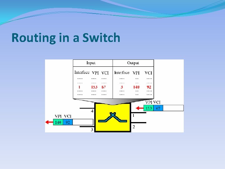
Routing in a Switch
ATM Signaling �ATM end-users require the capability to establish connections across the network �Two Types of End-to-End Connections o Permanent Virtual Circuit (PVC) o Switched Virtual Circuit(SVC) �The signaling mechanism used for ATM is based on ISDN Signaling System Number 7 (SS 7)
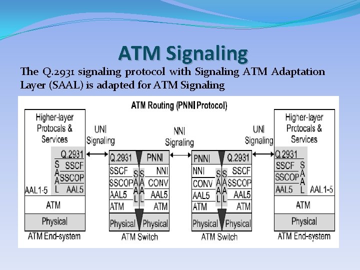
ATM Signaling The Q. 2931 signaling protocol with Signaling ATM Adaptation Layer (SAAL) is adapted for ATM Signaling
Signaling ATM Adaptation Layer (SAAL) �The SAAL provides reliable transport of signaling messages between two ATM systems �Composed of two sub layers o Common part o Service-specific part
Service-Specific Part Subdivided into � Service-Specific Coordination Function (SSCF) � Service-Specific Connection Oriented Protocol (SSCOP)
Virtual Circuit Connection (VCC) Types 4 Classes �Point-to-point (pt-pt) �Point-to-multipoint (pt-mpt) �Multipoint-to-point (mpt-pt) �Multipoint-to-multipoint (mpt-mpt)
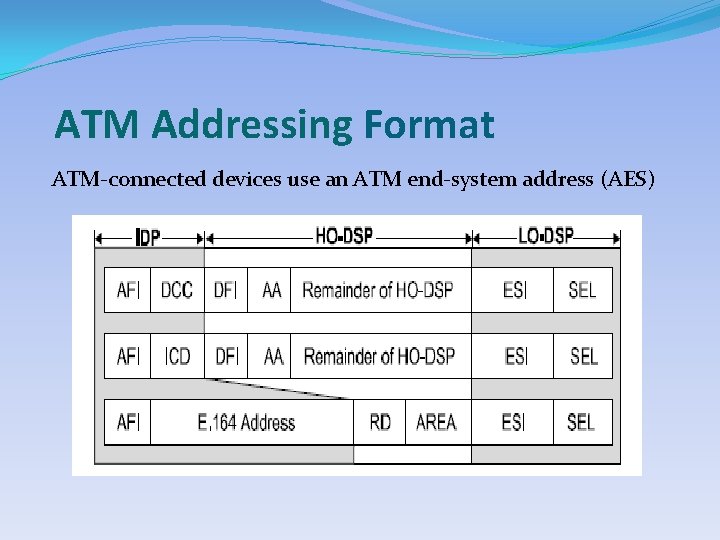
ATM Addressing Format ATM-connected devices use an ATM end-system address (AES)
Initial Domain Part (IDP) This part contains �Address Format Identifier (AFI) �Initial Domain Identifier (IDI) �The IDI o Data Country Code (DCC) o International Code Designator (ICD)
Domain Specific Part (DSP) Contains �High-Order Part (HO-DSP) �Lower-Order Part (LO-DSP)

THANK YOU
High-Order Part (HO-DSP) Contains �Domain Format Identifier (DFI) �Address Authority (AA) �Routing Domain (RD) � Area
Lower-Order Part (LO-DSP) Contains �End-System Identifier (ESI) � Selector (SEL)

THANK YOU
- Slides: 45