ASSEMBLY LINE SIMULATION WITH MULTIROBOT CONTROL Peter Mc

ASSEMBLY LINE SIMULATION WITH MULTI-ROBOT CONTROL Peter Mc. Hugh, Thomas Zack, Kyle Fecteau Advisor: Dr. Carlos Luck

Overview � Introduction to the Robots � Staubli, � � Scara, and Microbot Tennis Ball Assembly Line Mechanical Designs and Modifications � Stäubli Gripper � Pallet � SCARA Gripper � Rotary � Lid � � Nest Programming Work That Can Be Done Next Year

Stäubli Scara

Microbot � � � Establish connection through serial port Accepts string commands through serial port, if command is executed outputs a 1 to user. Turntable Accessory

2009/2010 Robotics Research Group Goals o Create a practical use of the Staubli and Scara using the 2008/2009 Research Group multirobot control programs Tennis Ball Assembly Line o Design and Produce: o Gripper for Stäubli and Scara o Pallet o Turntable Attachment o Lid Nest o Write Program

Tennis Ball Assembly Line

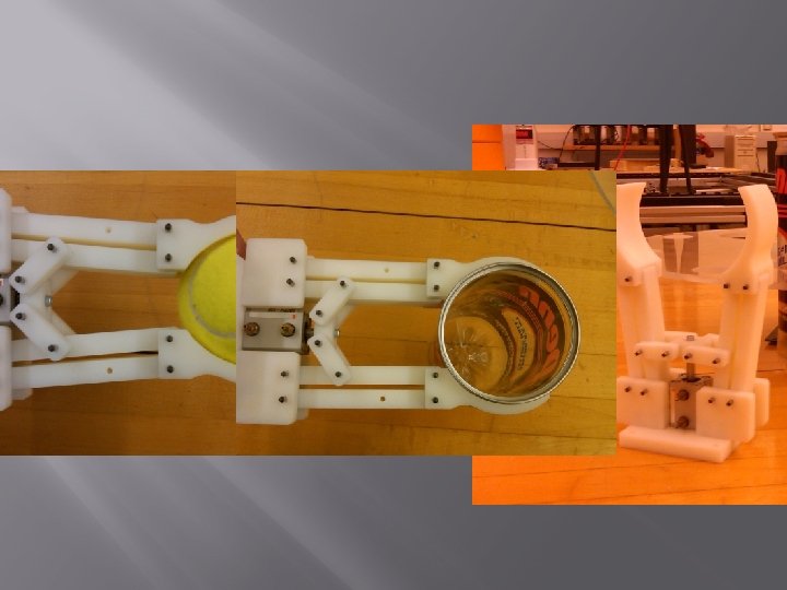
Mechanical Design of Stäubli Gripper � � Mechanically operate using a pneumatic cylinder Pick up tennis ball tube Pick up tennis ball Withstand a 10. 5 lbf generated from the 60 psi

Mechanical Design of Stäubli Gripper

Mechanical Design of Stäubli Gripper

Scara Gripper

Scara Gripper • Vaccum Pump that is connected from the solenoid control valve to the gripper tool suction cup. • (2) Rollers on each side of the suction cup. • The suction cup has enough compression when the lid is being placed on the tube that the rollers can put pressure against the top of the lid. The gripper rotates 180° clockwise and counterclockwise to seal the lid.

Mechanical Design of Pallet

Design for Turntable

Design of Lid Nest � � � Capable of securing 3 lids Allow access to SCARA vacuum gripper Be removable

Robot Control Programming � Robots control consists of Staubli Adept controller, Scara Adept controller, and the host computer.

Adept Programming • Both the Stäubli and Scara use V+ programming to control the movements of the robots. . PROGRAM placelid 1() TOOL TRANS(0, 0, 100, 0, 0, 0) CALL tennisballhome() BREAK SET a = TRANS(370, -151, 56, 0, 180, 0) BREAK APPRO a, 50 BREAK CALL close()

RCML Programming � Robot Control Markup Language � Created language that uses XML programs to control the robots in the workspace from a host computer. A <step> command is used to send instruction to the respective serial port. �

Sample RCML Code <configuration> <conn variable= "staubli" connection= "COM 2" interpreter="api. Adept. Interpreter"/> <conn variable= "scara" connection= "COM 4" interpreter="api. Adept. Interpreter"/> <conn variable= "microbot" connection= "COM 5" interpreter="api. Microbot. Interpreter"/> </configuration> <execution timeout= "30000"> <for count= "infinity"> <set> <step>scara. wait 1</step> <step>scara. wait 2</step> <sequence> <step>staubli. tubetotrack</step> <step>staubli. pickrotary</step> <step>Microbot. reset()</step> <step>Microbot. read()</step> <step>microbot. xx 1(100, 0, -272, 0, 0)</step>

Java Programming • • Java is used as the host PC programming language. Existing code interprets the command set by the RCML program and distributes a string to the serial port by use of the Adept. Interpreter and Microbot. Interpreter.

Java Programming � The XX 1 microbot was initialized in the Microbot. Interpreter to control the rotary table: XX 1(speed, m 1, m 2, m 3, m 4, m 5, m 6, t 1, t 2, out)

Work That Can Be Done � � � Java Program For I/O Control Sensor for Microbot rotary table Increase Efficiency � Simultaneous movements of the robots � Add more pallets � Design of way to load rotary table or system to supply continuous operation

QUESTIONS?
- Slides: 23