
ASME TURBO EXPO 2010 Glasgow Scotland UK Thermal
ASME TURBO EXPO 2010, Glasgow, Scotland, UK Thermal Management and Rotordynamic Performance of a Hot Rotor-Gas Foil Bearings System Part 1: Measurements is San Andrés st-Childs Professor llow ASME xas A&M University Keun Ryu Research Assistant Texas A&M University Tae Ho Kim Senior Research Scientist Korea Institute of Science and Technology ASME paper GT 2010 -22981 J. Eng. Gas Turbines Power (in press) This material is based upon work supported by NASA Research Announcement NNH 06 ZEA 001 N-SSRW 2, Fundamental Aeronautics: Subsonic Rotary Wing Project 2 # 32525/39600/ME and the Turbomachinery Research Consortium
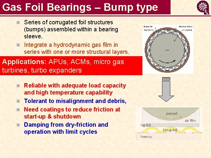
Gas Foil Bearings – Bump type n Series of corrugated foil structures (bumps) assembled within a bearing sleeve. n Integrate a hydrodynamic gas film in series with one or more structural layers. Applications: APUs, ACMs, micro gas turbines, turbo expanders n Reliable with adequate load capacity and high temperature capability n Tolerant to misalignment and debris, n Need coatings to reduce friction at start-up & shutdown n Damping from dry-friction and operation with limit cycles
Gas Foil Bearings Issues n Endurance: performance at start up & shut down (lift off speed) n Little test data for rotordynamic force coefficients & operation with limit cycles (sub harmonic motions) n Thermal management for high temperature applications (gas turbines, turbochargers) n Predictive models lack validation for GFB operation at HIGH TEMPERATURE
Overview – Thermal management n Heshmat et al (2005): demonstrates hot (650 C) GFB operation in a turbojet engine to 60 krpm. Cooling flow rates to 570 L/min still give large axial thermal gradients (13ºC/cm) n Dykas (2006): investigates thermal management in foil thrust bearings. Cooling flow rates, to 450 L/min, increase bearing load capacity at high rotor speeds. Inadequate thermal management can give thermo-elastic distortions affecting load capacity of test FB n Radil et al (2007): evaluate effectiveness of three cooling methods (axial cooling, direct and indirect shaft cooling) for thermal management in a hot GFB environment n San Andrés et al (2009): forced cooling flow has limited effectiveness at low rotor temperatures. At high test temperatures, large cooling flows (turbulent) remove heat more efficiently Gases have limited thermal capacity, hence (some) bearings demand large cooling flows to remove heat from hot rotor sections.
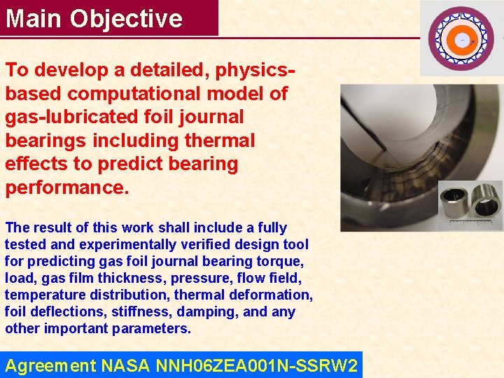
Main Objective To develop a detailed, physicsbased computational model of gas-lubricated foil journal bearings including thermal effects to predict bearing performance. The result of this work shall include a fully tested and experimentally verified design tool for predicting gas foil journal bearing torque, load, gas film thickness, pressure, flow field, temperature distribution, thermal deformation, foil deflections, stiffness, damping, and any other important parameters. Agreement NASA NNH 06 ZEA 001 N-SSRW 2
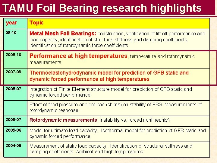
TAMU Foil Bearing research highlights year Topic 08 -10 Metal Mesh Foil Bearings: construction, verification of lift off performance and load capacity, identification of structural stiffness and damping coefficients, identification of rotordynamic force coefficients 2008 -10 Performance at high temperatures, temperature and rotordynamic measurements 2007 -09 Thermoelastohydrodynamic model for prediction of GFB static and dynamic forced performance at high temperatures 2005 -07 Integration of Finite Element structure model for prediction of GFB static and dynamic forced performance Effect of feed pressure and preload (shims) on stability of FBS. Measurements of rotordynamic response. 2005 -07 Rotordynamic measurements: instability vs. forced nonlinearity? 2005 -06 Model for ultimate load capacity, Isothermal model for prediction of GFB static and dynamic forced performance 2004 -09 Measurement of static load capacity, Identification of structural stiffness and damping coefficients. Ambient and high temperatures
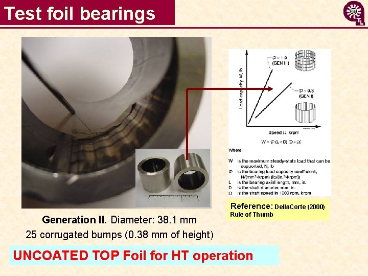
Test foil bearings Reference: Della. Corte (2000) Generation II. Diameter: 38. 1 mm 25 corrugated bumps (0. 38 mm of height) Rule of Thumb UNCOATED TOP Foil for HT operation
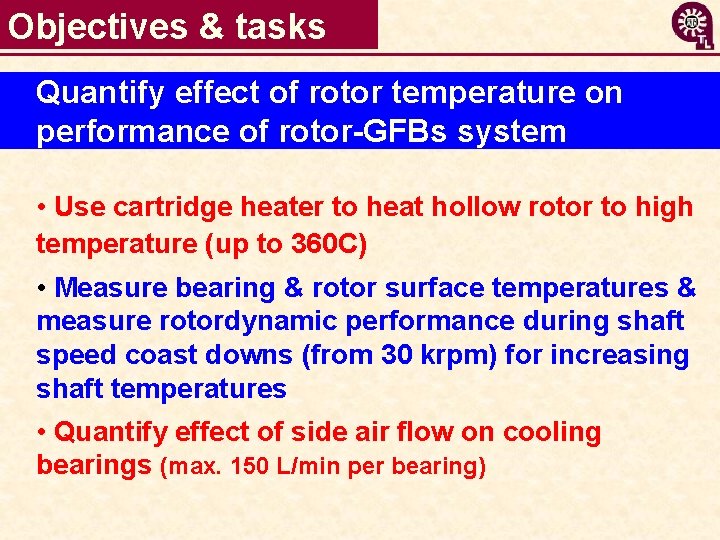
Objectives & tasks Quantify effect of rotor temperature on performance of rotor-GFBs system • Use cartridge heater to heat hollow rotor to high temperature (up to 360 C) • Measure bearing & rotor surface temperatures & measure rotordynamic performance during shaft speed coast downs (from 30 krpm) for increasing shaft temperatures • Quantify effect of side air flow on cooling bearings (max. 150 L/min per bearing)
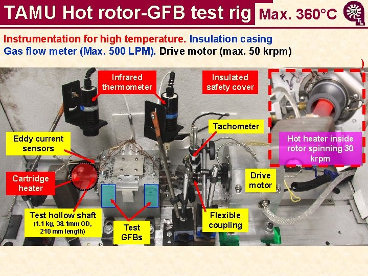
TAMU Hot rotor-GFB test rig Max. 360°C Instrumentation for high temperature. Insulation casing Gas flow meter (Max. 500 LPM). Drive motor (max. 50 krpm) ) Infrared thermometer Insulated safety cover Tachometer Eddy current sensors Hot heater inside rotor spinning 30 krpm Drive motor Cartridge heater Test hollow shaft (1. 1 kg, 38. 1 mm OD, 210 mm length) Test GFBs Flexible coupling
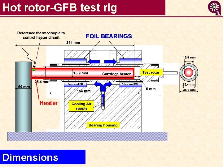
Hot rotor-GFB test rig FOIL BEARINGS Heater Dimensions
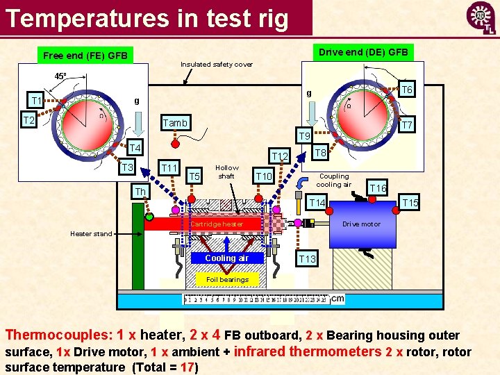
Temperatures in test rig Drive end (DE) GFB Free end (FE) GFB Insulated safety cover 45º T 1 g T 2 T 6 g Tamb T 7 T 9 T 4 T 3 T 12 T 11 T 5 Hollow shaft Th T 8 T 10 Coupling cooling air T 16 T 14 T 15 Drive motor Cartridge heater Heater stand Cooling air T 13 Foil bearings Thermocouples: 1 x heater, 2 x 4 FB outboard, 2 x Bearing housing outer surface, 1 x Drive motor, 1 x ambient + infrared thermometers 2 x rotor, rotor surface temperature (Total = 17)
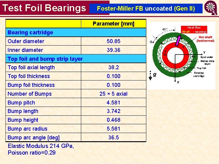
Test Foil Bearings Foster-Miller FB uncoated (Gen II) Parameter [mm] Bearing cartridge Outer diameter 50. 85 Inner diameter 39. 36 Top foil and bump strip layer Top foil axial length 38. 2 Top foil thickness 0. 100 Bump foil thickness 0. 100 Number of Bumps 25 × 5 axial Bump pitch 4. 581 Bump length 3. 742 Bump height 0. 468 Bump arc radius 5. 581 Bump arc angle [deg] 36. 5 Elastic Modulus 214 GPa, Poisson ratio=0. 29
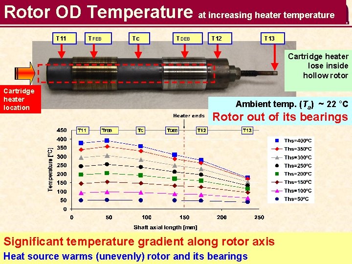
Rotor OD Temperature at increasing heater temperature T 11 TFEB Tc TDEB T 12 T 13 Cartridge heater lose inside hollow rotor Cartridge heater location Ambient temp. (Ta) ~ 22 °C Rotor out of its bearings Significant temperature gradient along rotor axis Heat source warms (unevenly) rotor and its bearings
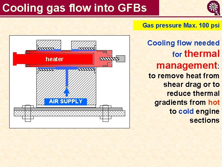
Cooling gas flow into GFBs Gas pressure Max. 100 psi Cooling flow needed heater AIR SUPPLY for thermal management: to remove heat from shear drag or to reduce thermal gradients from hot to cold engine sections
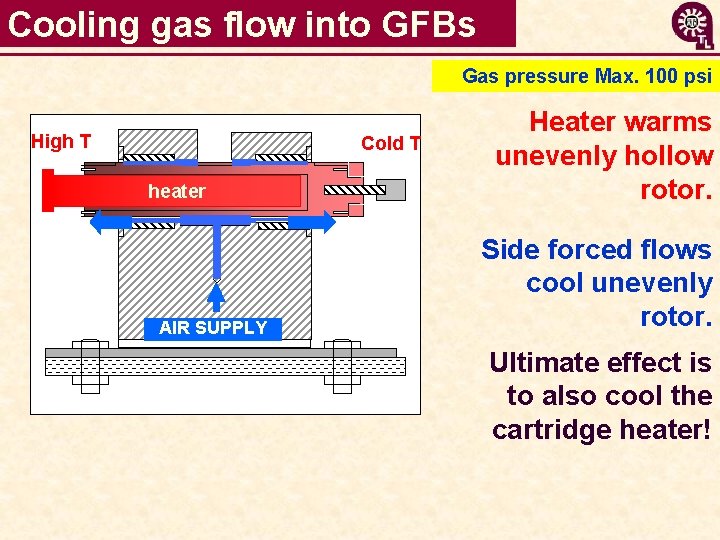
Cooling gas flow into GFBs Gas pressure Max. 100 psi High T Cold T heater AIR SUPPLY Heater warms unevenly hollow rotor. Side forced flows cool unevenly rotor. Ultimate effect is to also cool the cartridge heater!
Video: Operation of hot rotor-GFB test rig
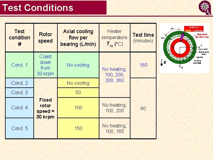
Test Conditions Test condition # Rotor speed Axial cooling flow per bearing (L/min) Cond. 1 Coast down from 30 krpm No cooling Cond. 2 No cooling Cond. 3 50 Cond. 4 Cond. 5 Fixed rotor speed = 30 krpm Heater temperature Ths (ºC) No heating, 100, 200, 360 100 No heating, 100, 200 150 No heating, 100, 165 Test time (minutes) 160 60
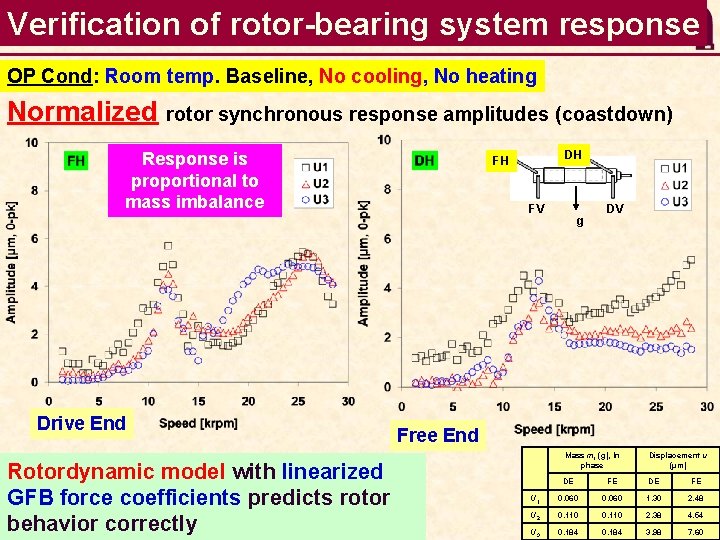
Verification of rotor-bearing system response OP Cond: Room temp. Baseline, No cooling, No heating Normalized rotor synchronous response amplitudes (coastdown) Response is proportional to mass imbalance Drive End Rotordynamic model with linearized GFB force coefficients predicts rotor behavior correctly DH FH FV g DV Free End Mass mi (g), In phase Displacement u (µm) DE FE U 1 0. 060 1. 30 2. 48 U 2 0. 110 2. 38 4. 54 U 3 0. 184 3. 98 7. 60
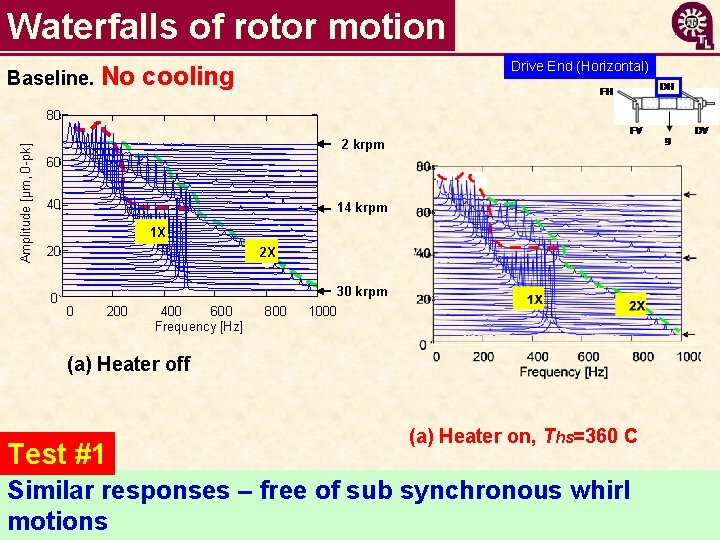
Waterfalls of rotor motion Baseline. No Drive End (Horizontal) cooling Amplitude [µm, 0 -pk] 0. 08 80 X_left. WF 0. 707 2 krpm 0. 06 60 40 0. 04 14 krpm 1 X 0. 02 20 2 X 00 0 0 30 krpm 200 trace 1 400 600 400 X_left. Xaxis 600 Frequency [Hz] 800 1000 (a) Heater off Test #1 (a) Heater on, Ths=360 C Similar responses – free of sub synchronous whirl motions
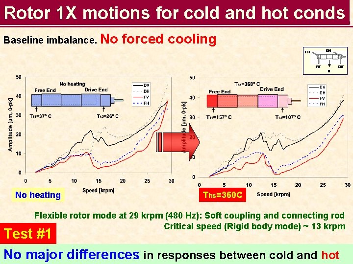
Rotor 1 X motions for cold and hot conds Baseline imbalance. No No heating forced cooling Ths=360 C Flexible rotor mode at 29 krpm (480 Hz): Soft coupling and connecting rod Critical speed (Rigid body mode) ~ 13 krpm Test #1 No major differences in responses between cold and hot
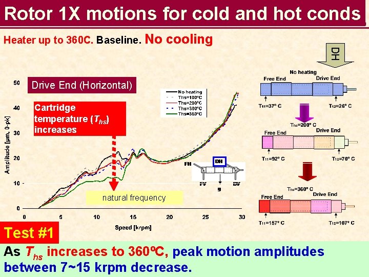
Rotor 1 X motions for cold and hot conds Heater up to 360 C. Baseline. No cooling DH Drive DH End (Horizontal) Cartridge temperature (Ths) increases natural frequency Test #1 As Ths increases to 360ºC, peak motion amplitudes between 7~15 krpm decrease.
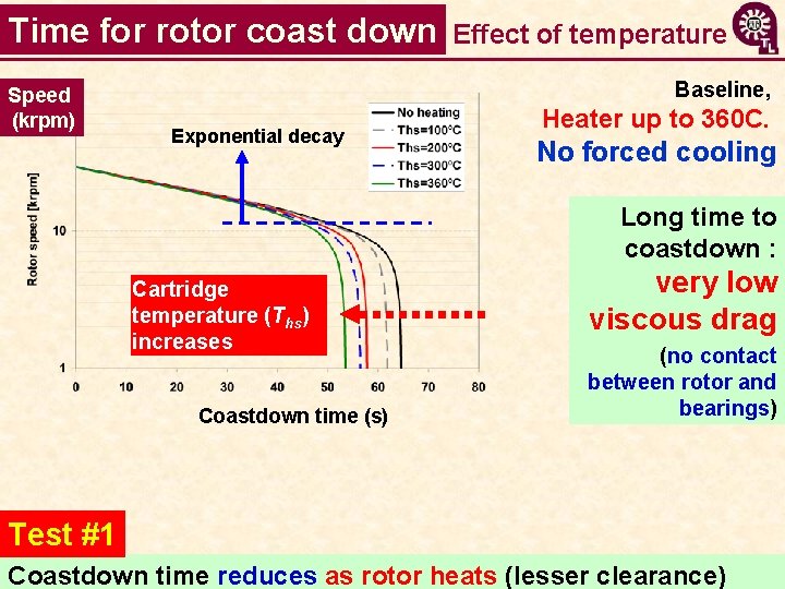
Time for rotor coast down Speed (krpm) Effect of temperature Baseline, Exponential decay Heater up to 360 C. No forced cooling Long time to coastdown : Cartridge temperature (Ths) increases Coastdown time (s) very low viscous drag (no contact between rotor and bearings) Test #1 Coastdown time reduces as rotor heats (lesser clearance)
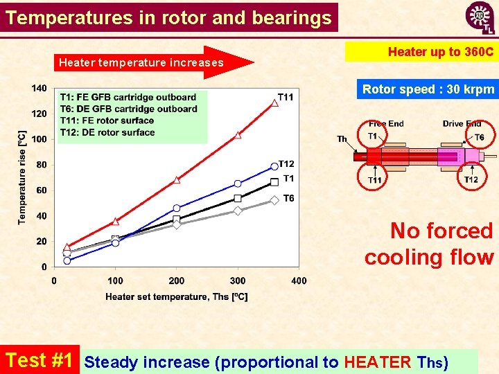
Temperatures in rotor and bearings Heater temperature increases Heater up to 360 C Rotor speed : 30 krpm No forced cooling flow Test #1 Steady increase (proportional to HEATER Ths)
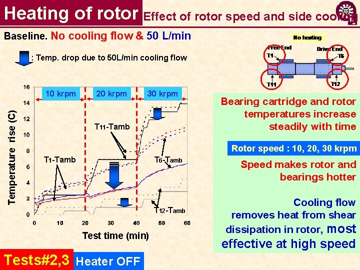
Heating of rotor Effect of rotor speed and side cooling Baseline. No cooling flow & 50 L/min : Temp. drop due to 50 L/min cooling flow Temperature rise (C) 10 krpm 20 krpm 30 krpm T 11 -Tamb Bearing cartridge and rotor temperatures increase steadily with time Rotor speed : 10, 20, 30 krpm T 1 -Tamb T 6 -Tamb T 12 -Tamb Test time (min) Tests#2, 3 Heater OFF Speed makes rotor and bearings hotter Cooling flow removes heat from shear dissipation in rotor, most effective at high speed
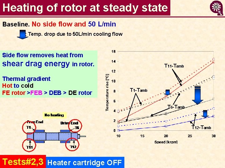
Heating of rotor at steady state Baseline. No side flow and 50 L/min : Temp. drop due to 50 L/min cooling flow Side flow removes heat from shear drag energy in rotor. Thermal gradient Hot to cold FE rotor >FEB > DE rotor T 11 -Tamb T 6 -Tamb T 12 -Tamb Tests#2, 3 Heater cartridge OFF
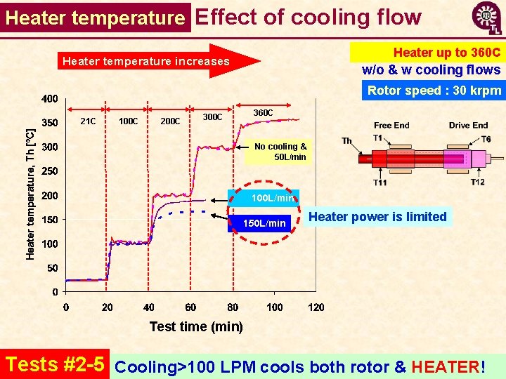
Heater temperature Effect of cooling flow Heater up to 360 C Heater temperature increases w/o & w cooling flows Rotor speed : 30 krpm 21 C 100 C 200 C 360 C 300 C No cooling & 50 L/min 100 L/min 150 L/min Heater power is limited Test time (min) Tests #2 -5 Cooling>100 LPM cools both rotor & HEATER!
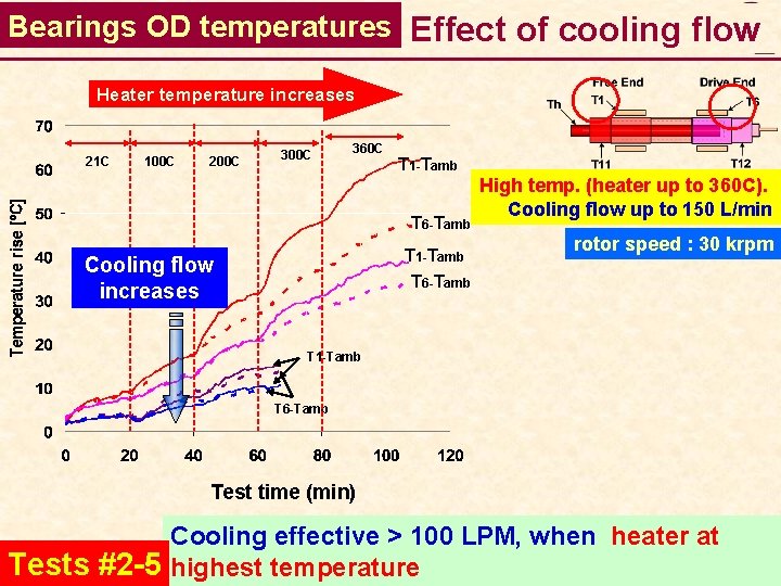
Bearings OD temperatures Effect of cooling flow Heater temperature increases 21 C 100 C 200 C 360 C T 1 -Tamb T 6 -Tamb Cooling flow increases High temp. (heater up to 360 C). Cooling flow up to 150 L/min rotor speed : 30 krpm T 1 -Tamb T 6 -Tamb Test time (min) Tests #2 -5 Cooling effective > 100 LPM, when heater at highest temperature
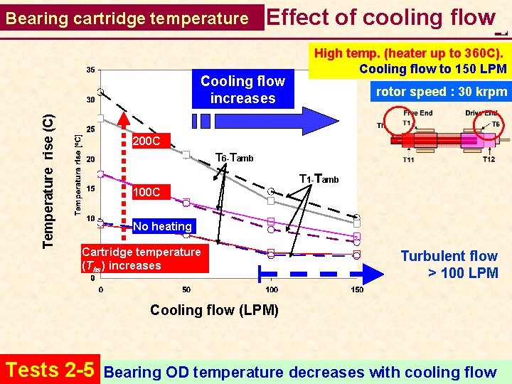
Bearing cartridge temperature Effect of cooling flow Temperature rise (C) Cooling flow increases High temp. (heater up to 360 C). Cooling flow to 150 LPM rotor speed : 30 krpm 200 C T 6 -Tamb T 1 -Tamb 100 C No heating Cartridge temperature (Ths) increases Turbulent flow > 100 LPM Cooling flow (LPM) Tests 2 -5 Bearing OD temperature decreases with cooling flow
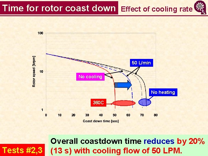
Time for rotor coast down Effect of cooling rate 50 L/min No cooling No heating 360 C Overall coastdown time reduces by 20% Tests #2, 3 (13 s) with cooling flow of 50 LPM.
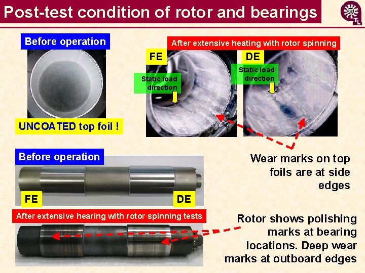
Post-test condition of rotor and bearings Before operation After extensive heating with rotor spinning FE DE Static load direction UNCOATED top foil ! Before operation FE Wear marks on top foils are at side edges DE After extensive hearing with rotor spinning tests Rotor shows polishing marks at bearing locations. Deep wear marks at outboard edges
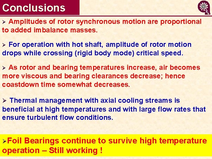
Conclusions Amplitudes of rotor synchronous motion are proportional to added imbalance masses. Ø For operation with hot shaft, amplitude of rotor motion drops while crossing (rigid body mode) critical speed. Ø As rotor and bearing temperatures increase, air becomes more viscous and bearing clearances decrease; hence coastdown time somewhat decreases. Ø Ø Thermal management with axial cooling streams is beneficial at high temperatures and with large flow rates that ensure turbulent flow conditions. ØFoil Bearings continue to survive high temperature operation – Still working !

Acknowledgments Thanks support of • NASA GRC (2007 -09) & Dr. Samuel Howard • NSF (2003 -06), TRC (2004 -08) • Foster-Miller (FBs) Learn more http: //rotorlab. tamu. edu Questions ? Next presentation shows predictions benchmarked to test data
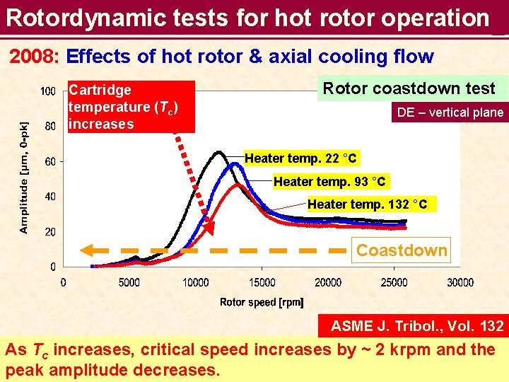
Rotordynamic tests for hot rotor operation 2008: Effects of hot rotor & axial cooling flow Cartridge temperature (Tc) increases Rotor coastdown test DE – vertical plane Heater temp. 22 °C Heater temp. 93 °C Heater temp. 132 °C Coastdown ASME J. Tribol. , Vol. 132 As Tc increases, critical speed increases by ~ 2 krpm and the peak amplitude decreases.
- Slides: 33