ASME Code Section VIII Pressure vessel design Leonard


")
 Assume t. – 2)")

=Do")

 Determine the required thickness of a shell. n 2)")
 Determine the required thickness of a hemispherical")
 Determine the required thickness of a seamless ellipsoidal head.")

Calculate unstiffened design length, L and Do of")

Calculate unstiffened design length, L and")
 (1/16 inches step) n n n n 0. 1875 0. 25")
- Slides: 21
ASME Code Section VIII Pressure vessel design Leonard D. Tijing Ph. D Candidate
Factor A
Factor A
Factor B : Fig. CS-2 For most common materials
Fig. NFA-1 Aluminum alloy 3003
Internal pressure formulas
Heads
Allowable stress for carbon and low alloy steel (S)
External pressure: Sphere and hemispherical head n Procedure: – 1) Assume t. – 2) Calculate A, A=0. 125/(Ro/t) – 3) Get value of B. § If A falls to the left, use Pa=0. 0625 E/(Ro/t)2 – 4) Calculate Pa=B/(Ro/t)
External pressure: Ellipsoidal head n Procedure: – Same with sphere procedure. – Use Ro=0. 9 Do
External pressure: Torispherical head n Procedure: – Same procedure. – Use Ro(maximum)=Do
Example: Internal pressure n Design data: – P = 100 psi – S = SA 515 -70 plate at 650 o. F – E = 0. 85 (spot-examined for shell and semispherical head) – E = 1. 0 (seamless head) – R = 48 in – D = 96 in – t = required wall thickness – CA = 0. 125
Internal pressure: Cylindrical shell 1) Determine the required thickness of a shell. n 2) Determine the MAWP, P for the design thickness used when the vessel is in new condition. n
Internal pressure: Sphere and hemispherical head 1) Determine the required thickness of a hemispherical head. n 2) Determine the MAWP, P for the head design thickness used when it is in new condition. n
Internal pressure: Ellipsoidal head 1) Determine the required thickness of a seamless ellipsoidal head. n 2) Determine the MAWP, P for the seamless head design thickness used when it is in corroded condition. n
Example 1: External pressure n Design information: – P = full vacuum – T = 500 o. F – Shell and head material = SA-285 Gr. B, S=27 ksi – CA = 0. 0625 in. n Question: Is 7/16 in thickness acceptable?
External pressure: Solution procedure n n 1)Calculate unstiffened design length, L and Do of the shell 2) Determine ratios L/Do and Do/t 3) Determine value of A using figure 4) Get value of B from graph. – If A is to the left of the graph, calculate Pa=2 AE/[3(Do/t)] 5) If there is B, use Pa=4 B/[3(Do/t)] n 6) Compare Pa with design external pressure. If Pa is greater, thickness is acceptable n
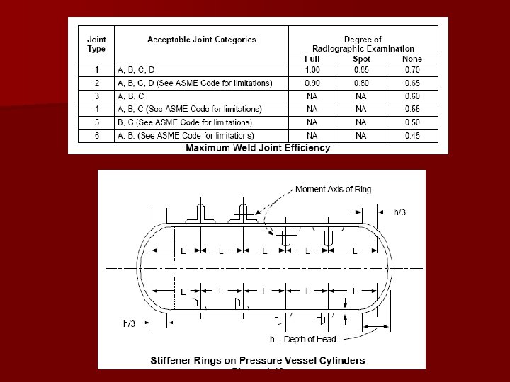
Example 2: External pressure with stiffeners n n n n P = 15 psig Do = 96 in L = 48 ft Heads 2: 1 ellipsoidal Material of shell SA 285 C plate T = 500 o. F E = see chart t=?
Example: External pressure Vessel with stiffeners n n 1)Calculate unstiffened design length, L and Do of the shell 2) Determine ratios L/Do and Do/t 3) Determine value of A using figure 4) Get value of B from graph. – If A is to the left of the graph, calculate Pa=2 AE/[3(Do/t)] 5) If there is B, use Pa=4 B/[3(Do/t)] n 6) Compare Pa with design external pressure. If Pa is greater, thickness is acceptable n
Thickness range (inches) (1/16 inches step) n n n n 0. 1875 0. 25 0. 3125 0. 375 0. 4375 0. 5625 0. 6875 n 0. 8125 n 0. 875 n 0. 9375 n 1. 0 … 6. 0 n