ARUBA francisnetease com tw Aruba controller 620 4

ARUBA 無線網路教育訓練 蔡億慶 francis@netease. com. tw

機器外觀介紹 Aruba controller 620 4

機器外觀介紹 AP 125 天線 Po. E Ethernet AP 125 5

基礎操作介面介紹 l Monitoring l Configuration l Diagnostics l Maintenance l Plan l Events l Reports 7

基礎操作介面介紹 l Monitoring -Network -Controller -WLAN -Voice -Debug 8

基礎操作介面介紹 l Configuration -Wizards -Network -Security -Wireless -Management -Advanced Services 9

基礎操作介面介紹 l Diagnostics -Network -General -Access Point 10

基礎操作介面介紹 l Maintenance -Controller -File -WLAN 11

L 2 Deployment l In a L 2 deployment, WLAN controller acts as an Ethernet bridge Ø After authentication, frames from client are bridged onto L 2 network l 802. 1 q VLANs can be used Ø Clients can all be on same VLAN Ø Client can be assigned to VLAN based on ESSID, location, or authentication result (802. 1 x) l Uplink ports can be 802. 1 q tagged Ø Or a different physical uplink port can be used per VLAN l Address assignment through external DHCP server normally (internal DHCP server available) Ø Client broadcasts for DHCP, controller bridges the broadcast on user’s VLAN 13

Theory of Operations Second Floor 10. 1. 11. 36 AP 4/2 nd Floor 11 10. 1. 11. 42 AP 3/2 nd Floor First Floor VLAN 14 10. 1. 10. 68 AP 2/1 st Floor 10 10. 1. 10. 96 AP 1/1 st Floor Data Center 14 VLAN 14: 10. 1. 14. 6/24 loopback: 10. 1. 14. 7/32 DHCP E-mail 14

Theory of Operations Second Floor 150 -200 Users per VLAN 10. 1. 11. 36 AP 4/2 nd Floor VLAN 10. 1. 11. 42 AP 3/2 nd Floor 11 101 First Floor 10. 1. 10. 68 VLAN AP 2/1 st Floor 10 10. 1. 10. 96 AP 1/1 st Floor Data Center 14 802. 1 q 14, 100, 101 DHCPE-mail 100 Layer 3 Switch vlan 100: 10. 1. 100. 1/24 vlan 101: 10. 1. 101. 1/24 Mobility Controller vlan 14: 10. 1. 14. 6/24 loopback: 10. 1. 14. 7/32 vlan 100 vlan 101 ap group “ 1 st Floor” vlan 100 ap group “ 2 nd Floor” vlan 101 15

Theory of Operations GRE Second Floor 1 10. 1. 11. 36 802. 3 AP 4/2 nd Floor 4 11 SIP: 10. 96 DIP: 14. 7 802. 11 802. 3 10. 1. 11. 42 AP 3/2 nd Floor 1 0 DHCP Request 0 First Floor 10. 1. 10. 68 AP 2/1 st Floor 10 10. 1. 10. 96 AP 1/1 st Floor 14 Data Center 802. 1 q 14, 100, 101 DHCP E-mail Layer 3 switch VLAN 100: 10. 1. 100. 1/24 VLAN 101: 10. 1. 101. 1/24 Mobility Controller VLAN 14: 10. 1. 14. 6/24 loopback: 10. 1. 14. 7/32 VLAN 100 VLAN 101 ap group “ 1 st Floor” vlan 100 ap group “ 2 nd Floor” vlan 101 16

Theory of Operations GRE Second Floor 1 10. 1. 11. 36 802. 3 AP 4/2 nd Floor 4 11 SIP: 14. 7 DIP: 10. 96 802. 11 802. 3 10. 1. 11. 42 AP 3/2 nd Floor 1 0 0 DHCP Reply 10. 1. 100. 32 First Floor 10. 1. 10. 68 AP 2/1 st Floor 10 10. 1. 10. 96 AP 1/1 st Floor 14 Data Center 802. 1 q 14, 100, 101 DHCP E-mail 10. 1. 100. 32 Layer 3 switch VLAN 100: 10. 1. 100. 1/24 VLAN 101: 10. 1. 101. 1/24 Mobility Controller VLAN 14: 10. 1. 14. 6/24 loopback: 10. 1. 14. 7/32 VLAN 100 VLAN 101 ap group “ 1 st Floor” vlan 100 ap group “ 2 nd Floor” vlan 101 17

Theory of Operations Second Floor 10. 1. 11. 36 AP 4/2 nd Floor 11 10. 1. 11. 42 AP 3/2 nd Floor First Floor GRE 1 4 SIP: 11. 42 802. 3 DIP: 14. 7 10. 1. 10. 68 AP 2/1 st Floor 10. 1. 100. 32 10 10. 1. 10. 96 AP 1/1 st Floor 14 Data Center 802. 1 q 14, 100, 101 DHCP E-mail 802. 3 802. 11 1 DHCP Renew 0 10. 1. 100. 32 0 Layer 3 switch VLAN 100: 10. 1. 100. 1/24 VLAN 101: 10. 1. 101. 1/24 Mobility Controller VLAN 14: 10. 1. 14. 6/24 loopback: 10. 1. 14. 7/32 VLAN 100 VLAN 101 ap group “ 1 st Floor” vlan 100 ap group “ 2 nd Floor” vlan 101 18

Theory of Operations Second Floor 10. 1. 11. 36 AP 4/2 nd Floor 11 10. 1. 100. 32 10. 1. 11. 42 AP 3/2 nd Floor First Floor 802. 3 10. 1. 10. 68 AP 2/1 st Floor 10 10. 1. 10. 96 AP 1/1 st Floor 14 Data Center 802. 1 q 14, 100, 101 DHCP E-mail GRE 1 4 SIP: 14. 7 DIP: 11. 42 802. 11 802. 3 1 0 0 DHCP Reply 10. 1. 100. 32 Layer 3 switch VLAN 100: 10. 1. 100. 1/24 VLAN 101: 10. 1. 101. 1/24 Mobility Controller VLAN 14: 10. 1. 14. 6/24 loopback: 10. 1. 14. 7/32 VLAN 100 VLAN 101 ap group “ 1 st Floor” vlan 100 ap group “ 2 nd Floor” vlan 101 19

登入Controller l 使用GUI https: //x. x: 4343 default IP address : 172. 16. 0. 254 l 使用CLI 將console 控制線接至controller serial port serial setting 9600 8 n 1 21

Groups and Properties AP Group Wireless LAN RF Management Virtual AP Properties SSID AP Qo. S IDS a/g Radio Settings System Profile Vo. IP RF Optimizations Ethernet a/g Management AAA Regulatory Virtual AP Properties SSID SNMP AAA 22
 23")
Profiles (cont. ) 23

設定範例 l 在實驗室中,為了安全考量,SSID分類為 student:WPA 2 -PSK Guest:web authentication,不能存取student vlan l Vlan 分配: student :Vlan 1 IP 192. 168. 1. 0/24 Guest :Vlan 11 IP 192. 168. 11. 0/24 24

範例架構說明 l 無線存取架構 Internet 192. 168. 1. 254/24 192. 168. 1. 250/24 Firewall or IP sharing Switch 2. 4 or 5 Ghz 192. 168. 1. 249/24 25

設定步驟 l 新增student and Guest Vlan 、IP、DHCP l 新增student及Guest SSID l 設定student 屬性、role l 設定Guest firewall policy、role l 新增student及Guest aaa profile l 新增student及Guest Virtual AP profile l 新增Group l 新增AP 26

新增student and Guest Vlan l Network->Vlan->add l 新增Guest vlan 11,選擇2 -3為access port l Apply 27

設定student Vlan IP l 設定vlan 1 IP address l 下圖紅框 l Apply 1 192. 168. 1. 254 255. 0 28

設定Guest Vlan IP l l 設定vlan 11 IP address 下圖紅框1 下圖紅框2,啟用NAT Apply 11 2 192. 168. 11. 254 255. 0 1 3 29

新增Guest DHCP 4 1 5 2 Guest 192. 168. 11. 254 8. 8 192. 168. 11. 0 255. 0 3 30

新增 student及Guest SSID l 先在藍框處輸入 SSID-student->Add l 新增完SSID-student,在藍框處輸入SSID-Guest->Add 31

編輯 student SSID l 點選SSID-student->編輯內容 1 2 3 4 32

編輯Guest SSID l 點選SSID-Guest->編輯內容 1 2 3 33

設定Guest firewall policy 1 2 3 l 新增阻斷存取 192. 168. 1. 0/24 ACL l 新增上網連線ACL 34

設定Guest firewall policy、role 35

編輯Guest role l 編輯Guest role 36

編輯Guest role l 新增deny_student policy 1 2 編輯Guest role 3 37

編輯Guest role 4 5 l 設定Captive portal profile : default 38

新增student及Guest aaa profile l 先在藍框處輸入 AAA-student->Add l 新增完AAA-student,在藍框處輸入AAA-Guest->Add 39

編輯student aaa profile l 點選AAA-Student->編輯內容 l 將authenticated role 套用至AAA-Student profile,802. 1 x authentication default role 1 2 3 40

編輯student aaa profile l 設定 802. 1 x authentication profile l 選擇default-psk 2 1 3 41

編輯Guest aaa profile l 點選AAA-Guest->編輯內容 l 將guest role 套用至AAA-Guest profile Intial role 1 2 3 42

新增student及Guest Virtual AP profile l 先在藍框處輸入 VAP-student->Add l 新增完VAP-student,在藍框處輸入VAP-Guest->Add 43

編輯VAP-Student profile l 新增VAP-Student VLAN 1 1 2 3 44

編輯VAP-Student profile l 設定VAP-Student AAA profile l 選擇AAA profile AAA-student 2 1 3 45

編輯VAP-Student profile l 設定VAP-Student SSID profile l 選擇SSID profile SSID-student 2 1 3 46

編輯VAP-Guest profile l 新增VAP-Guest VLAN 11 1 2 3 47

編輯VAP-Guest profile l l 設定VAP-Guest SSID profile 選擇SSID profile SSID-Guest 設定VAP-Guest AAA profile 選擇AAA profile AAA-Guest 1 2 3 48

新增Group l 新增AP Group: 5 F-study l 編輯 5 F-study 2 3 1 49

編輯 5 F-study l 新增VAP-Student and VAP-Guest 1 2 3 50

設定AP l 將AP加入Group 1 4 5 2 3 51

設定AP 1 2 52

3 4修改AP name 5 53

MESH 設定 54

範例架構說明 l Mesh架構 Internet 192. 168. 1. 254/24 2. 4 Ghz Firewall or IP sharing 192. 168. 1. 249/24 192. 168. 1. 247/24 192. 168. 1. 250/24 5 Ghz 192. 168. 1. 248/24 55

設定步驟 l 設定mesh profile l 新增Group l 設定AP l 查看mesh 訊息 56

設定Mesh profile l 新增Mesh Profile l 設定加密: wpa 2 -psk-aes 1 2 5 3 4 6 7 57

編輯Mesh Radio Profile l Reselection mode: 1、reselect-anytime 2、reselect-never 3、startup-subthreshold 4、subthreshold-only l Metric algorithm: 1 、 best-link-rssi 2 、distributed-tree-rssi 58

新增Mesh Group 59

編輯Mesh Group 1 3 2 4 l 新增Mesh Profile 60

設定AP l 新增Mesh AP l 將AP加入Mesh Group 1 4 5 2 3 61

設定Mesh AP l 選擇AP Group : mesh 1 62

設定Mesh portal 2設定mesh portal及mesh point IP setting 3 5 4 設定Mesh point 3 4 5 63

觀察Mesh AP狀態 64

觀察Mesh AP狀態 l 觀察Mesh Point topology 65

觀察Mesh AP狀態 l 使用CLI觀察Mesh AP狀態 #show ap mesh topology #show ap mesh active 66


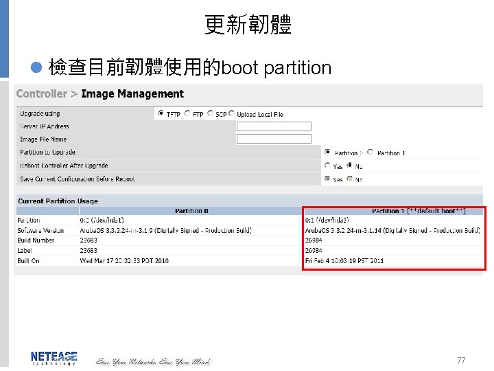
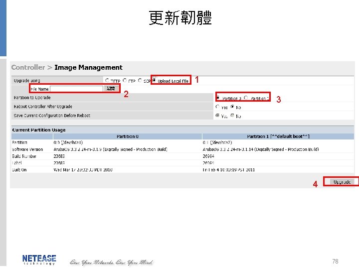
Concept Review: AP Boot Process 1. 2. 3. 4. 5. 6. Acquire IP Address “Discover” a controller Update code if necessary Obtain configuration information Build GRE Enable radio 68
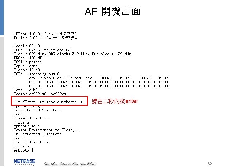

AP setting command l 清空指令 purge l 修改ap 的ip setenv ipaddr x. x setenv netmask x. x setenv gatewayip x. x setenv name xxx l 存檔save l 顯示設定print l 重開 boot 70
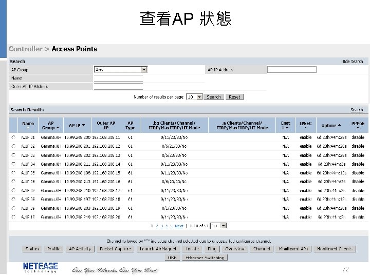

查看Cilent 73


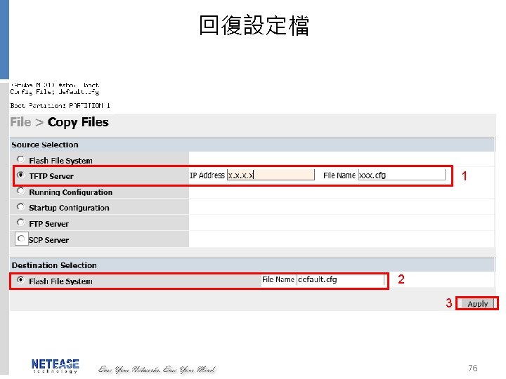
備份設定檔 l 備份startup config至tftp server 1 2 Ip address: x. x File name: xxxx. cfg 3 75

Q&A 79

THANK YOU !! 80
- Slides: 80