ARTIFICIAL LIFT Chapter 2 PTRT 2432 01 Vern


- Slides: 27
ARTIFICIAL LIFT Chapter 2 PTRT 2432 – 01 Vern Wilson
GAS LIFT SURFACE FACILITIES
GAS LIFT DOWNHOLE EQUIPM.
Objectives �Principles of gas lift �Discuss Continuous Flow, Intermittent Flow, Chamber Lift �Discuss Advantages �Discuss Disadvantages �Describe Plunger Lift – Advantages and Disadvantages
Redwater Gas Lift
Gas Lift Valve
Gas Lift Mandrels
Gas Lift Valves
Principles of Gas Lift �Came from water well pumping early 1800’s �Reservoir Characteristics – Porosity, Permeability, Sw �Reservoir Drive - Water 35, 80/Solution Gas 5, 30/ Gas Cap 20, 40 �Oil Properties – Density/Viscosity/Paraffin – Oil gas water �Well Test �Completion Data – Depth, h, type, pipe, deviation �Field Data – location/number of wells/electricitygas �Economic Thoughts -
CONTINUOUS FLOW �Open ended tubing �Low BHP �Inject down tubing �Inj Pressure + Hydrostatic Head > Annulus Hydrostatic �Similar characteristics to natural flow �Preferably used to increase flow in wells still producing �GENERALLY USES CASING INJECTION �Shallow wells – Hi BHP
INTERMITTENT FLOW �Started with gas lift valves - 1930 �Good for lower Pwf situations �Acts as a “gas plunger” lifting a slug of fluid �Sudden injection of gas through a large port in the lower gas lift valve results in rapid expulsion slug �Efficiently lift well for long period
Intermittent GL
CHAMBER GAS LIFT �Specialized form of gas lift �During periods when injection gas is off �Inflow accumulates in a chamber �When gas lift starts – large slug �Operates to very low Pwf
ADVANTAGES � Simple � Inexpensive � Flexible � Hi and Lo Volumes � Adverse conditions – Sand solids � Corrosion treatment � Crooked holes � Wireline Systems � Low Op Cost � Low Failure Rate � Urban Sites � Small Footprint
DISADVANTAGES �High Pressure Gas �Make up gas �Best on multiple wells �Limited to 10, 000 foot wells �Surging flow �Holds hi pressure on formation �Potential corrosion
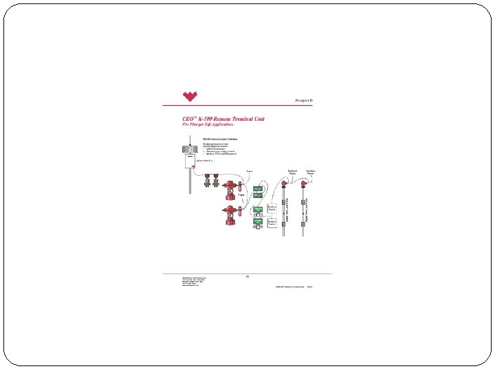
Plunger Lift
PLUNGER LIFT VIDEO �http: //www. pcsplungerlift. com/plungerlift/plungerlif t_work. html
PLUNGER LIFT �Least common – 1% or less �Well needs to be able to flow independently �Good on Hi GOR and lo productivity �Prolongs life of wells �Can be supplemented with external gas �Computer controlled �Paraffin, salt or scale can cause problems �Advantage – cost, space, deviated holes, unobtrusive, prevents scale and paraffin
PLUNGER SCHEMATIC
Typical Plunger Lift
BROWN #1 BEFORE Plunger Lift
PLUNGER LIFT – BROWN #1
Test 1 Review �What is Artificial Lift �Name some of the things you consider in design �Reservoir characteristics – K Φ �Reservoir Drives – think about the effects �PI �Economics – oil versus gas price �Bubble point �Drilling to TD and change of responsibility �Gas lift started when water wells were lifted
Review 2 �Calculate PI �Calculate P 1 V 1 �Hydrostatic pressure at TD �Equipment downhole and surface
Lab – Gas Lift Valve �Understand purpose of valve �Take valve apart and reassemble �Evaluate the action of the bellows.
HORIZONTAL DRILLING �http: //www. northernoil. com/drilling. php