Architectural and System Synthesis SOURCESDe Micheli Mark Manwaring


;")


 1. Tree-height reduction. 2. Constant and variable propagation. 3. Common")


")


. • Example:")


![High Level Synthesis for low power for(I=0; I<=2; I=I+1 begin @(posedge clk); Control if(fgb[I]%8;](https://slidetodoc.com/presentation_image_h/adc608258df1f6d1cd4b5ed5dc3e30bd/image-59.jpg "High Level Synthesis for low power for(I=0; I<=2; I=I+1 begin @(posedge clk); Control if(fgb[I]%8;")
 = switching(x)(Cout, Mux+Cin, Register)+switching(y) x (Cout, Register+Cin, De. Mux) switching(x)=switching(y)")


 specification •")


 • Free-floating (order")


 Library/ IP Vendors (Chipless) EDA Vendors Wafer Foundry Integrators")


![Literature [1] D. Gajski and N. Dutt, High-level Synthesis : Introduction to Chip and](https://slidetodoc.com/presentation_image_h/adc608258df1f6d1cd4b5ed5dc3e30bd/image-98.jpg "Literature [1] D. Gajski and N. Dutt, High-level Synthesis : Introduction to Chip and")
![[14] M. B. Srivastava, A. P. Chandrakasan, and R. W. Brodersen, "Predictive system shutdown](https://slidetodoc.com/presentation_image_h/adc608258df1f6d1cd4b5ed5dc3e30bd/image-99.jpg "[14] M. B. Srivastava, A. P. Chandrakasan, and R. W. Brodersen, \"Predictive system shutdown")


- Slides: 106
Architectural and System Synthesis SOURCESDe. Micheli Mark Manwaring Kia Bazargan Giovanni De Micheli Gupta Youn-Long Lin 99/09/13 Camposano, J. Hofstede, Knapp, Mac. Millen Lin High-level Synthesis
Outline • Motivation. • Compiling language models into abstract models. • Behavioral-level optimization and programlevel transformations. • Architectural synthesis: an overview.
Architectural Synthesis
Architectural Synthesis Problem • Specification • A sequencing graph • A set of functional resources • characterized by area and execution delay • • Constraints Tasks • This is what we need to do in behavioral synthesis! : ) • Constraints include: area, cycle time, latency, and throughput. • Area: number of modules/resources available or size of your silicon die. • Cycle time: how fast your clock runs • Latency: number of cycles for input data to result in a solution or result. • Throughput: Amount of data that can be processed in a given amount of time (usually involves pipelining) • Place operations in time and space • Determine detailed interconnection and control
Behavioral Optimization
Resource Binding • May have a pool of resources larger than required for problem • Map a constrained set of resources to given operations • Dedicated resources: each operation is bound to a single resource. 1. Resource pool: may include various kinds of multipliers (booth, array, etc) adders (tree, carry-lookahead, etc. ) multipurpose units (ALUs, multiplier/divider, etc. ) 2. Mapping a given set of resources to a set of known operations is one type of problem to solve. 3. Dedicated resource allocation is a one-to-one mapping.
Overview of Hardware Synthesis assign operations to physical resources under given constraints assign times to operations under given constraints reduce the amount of hardware, optimize the design in general. May be done with the consideration of additional constraints.
Architectural versus Logic Synthesis • Transform behavioral into structural view. • Architectural-level synthesis: • Architectural abstraction level. • Determine macroscopic structure. • Example of synthesis: major building blocks. • Logic-level synthesis: • Logic abstraction level. • Determine microscopic structure. • Example of synthesis: logic gate interconnection.
Synthesis and optimization
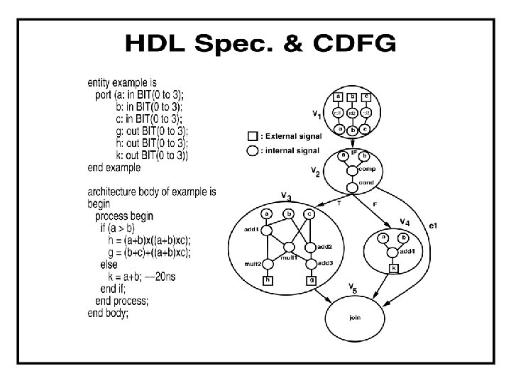
Example of HDL description of architecture diffeq { read (x, y, u, dx, a); repeat { xl = x + dx; ul = u - (3 * x * u * dx) - (3 * y * dx); yl = y + u * dx; c = x < a; x = xl; u = ul; y = yl; } until ( c ) ; write (y); }
Example of structures to implement this architecture Processes control and data
Principle of scheduling and allocation
Scheduling and Allocation a b c d e f g h 1 2 3 4
Internal representations • Internal representation is design back-bone of synthesis • Representations • Parse tree • Control-flow graph (CFG) • Data-flow graph (DFG, SFG) • Control/data-flow graph (CDFG) a e=a+b; g=c+d; f=e+b; h=f*g; b c +1 d +2 e +3 g f *1 h CDFG( control data flow graph )
Example of trade-off in architectural design
Architectural-level synthesis motivation • Raise input abstraction level. 1. 2. 3. 4. Reduce specification of details. Extend designer base. Self-documenting design specifications. Ease modifications and extensions. • Reduce design time. • Explore and optimize macroscopic structure: • Series/parallel execution of operations.
Design Space Exploration Delay We consider here totally different architectures Arch III Area
Stages of architectural-level synthesis 1. Translate HDL models into sequencing graphs. 2. Behavioral-level optimization: 1. Optimize abstract models independently from the implementation parameters. 3. Architectural synthesis and optimization: 1. Create macroscopic structure: • data-path and control-unit. 2. Consider area and delay information of the implementation. (on the global level)
Hardware and software compilation. hardware compilation.
High Level Synthesis Compilation Flow
Compilation and behavioral optimization • Software compilation: • Compile program into intermediate form. • Optimize intermediate form. • Generate target code for an architecture. • Hardware compilation: compilation • Compile HDL model into sequencing graph. • Optimize sequencing graph. • Generate gate-level interconnection for a cell library.
Compilation • Front-end: 1. 2. 3. 4. • Lexical and syntax analysis. Parse-tree generation. Macro-expansion. Expansion of meta-variables. Semantic analysis: 1. Data-flow and control-flow analysis. 2. Type checking. 3. Resolve arithmetic and relational operators.
Parse tree example a = p +q r
Behavioral-level optimization • Semantic-preserving transformations aiming at simplifying the model. • Applied to parse-trees or during their generation. • Taxonomy: 1. Data-flow based transformations. 2. Control-flow based transformations.
Data-Flow Based Transformations (review) 1. Tree-height reduction. 2. Constant and variable propagation. 3. Common sub-expression elimination. 4. Dead-code elimination. 5. Operator-strength reduction. 6. Code motion. We will illustrate each ns o i t a. m r n o o f i s t s n a n l o i i a ed t p r s t a s m re g co rm iscu a o f e s d s n in The e dur lar tra to be don e simi zation ar ptimi e r The ring o du e don
Tree-height reduction • Applied to arithmetic expressions. • Goal: Goal • Split into two-operand expressions to exploit hardware parallelism at best. • Techniques: • Balance the expression tree. • Exploit commutativity, associativity and distributivity.
Example of tree-height reduction using commutativity and associativity x = ( a + (b * c ) ) + d x = (a +d) + (b * c)
Example of tree-height reduction using distributivity x = a * (b c d +e) x = (a b) (c d) + (a e);
Examples of propagation • First Transformation type: Constant propagation: • a = 0, b = a +1, c = 2 * b, • a = 0, b = 1, c = 2, • Second Transformation type: Variable propagation: • a = x, b = a +1, c = 2 * a, • a = x, b = x +1, c = 2 * x,
Sub-expression elimination • Logic expressions: • Performed by logic optimization. • Kernel-based methods. • We discussed with factorization • Arithmetic expressions: • Search isomorphic patterns in the parse trees. • Example: • a = x +y, b = a +1, c = x +y, c = a.
Examples of other transformations • Dead-code elimination: • a = x; b = x +1; c = 2 * x; • a = x; can be removed if not referenced. • Operator-strength reduction: • a = x 2 ; b = 3 * x; • a = x * x; t = x << 1; b = x + t; • Code motion: • for (i = 1; i a * b) { } • t = a * b; for (i = 1; i t) { } • Multiplication only once.
Control- flow based transformations 1. Model expansion. Next slides 2. Conditional expansion. 3. Loop expansion. 4. Block-level transformations. • (will be discussed in more detail separately, presented on Friday)
Model expansion • Expand subroutine and flatten hierarchy as the result. • Useful to expand scope of other optimization techniques. • Problematic when routine is called more than once. • Example of model expansion: • • x = a +b; y = a * b; z = foo(x; y); foo(p; q) {t = q - p; return(t); } By expanding foo: foo does subtraction x = a +b; y = a * b; z = y - x
Conditional expansion • Transform conditional into parallel execution with test at the end. • Useful when test depends on late signals. • May preclude hardware sharing. • Always useful for logic expressions. • Example: • y = ab; if (a) {x = b + d; } else {x = bd; } • can be expanded to: x = a(b +d) +a’ bd • and simplified as: y = ab; x = y +d(a +b) Moves conditionals from control unit to data path
Loop expansion • Applicable to loops with data-independent exit conditions. • Useful to expand scope of other optimization techniques. • Problematic when loop has many iterations. • Example of loop expansion: • x = 0; for (i = 1; i 3; i ++) {x = x +1; } • Expanded to: x = 0; x = x +1; x = x +2; x = x +3 Can use various variable semantics
What is architectural synthesis and optimization • • Synthesize macroscopic structure in terms of buildingblocks. Explore area/performance trade-offs: 1. maximum performance implementations subject to area constraints. 2. minimum area implementations subject to performance constraints. • Determine an optimal implementation. • Create logic model for data-path and control.
Design space and objectives in architectural synthesis • Design space: • Set of all feasible implementations. • Implementation parameters: • Area. • Performance: • Cycle-time. • Latency. • Throughput (for pipelined implementations). • Power consumption
Three dimensional Design evaluation space
Hardware modeling 1. Circuit behavior: • Sequencing graphs. 2. Building blocks: • Resources. 3. Constraints: • Timing and resource usage. Our methods and data structures have to model them for architectural design
What are Resources? 1. Functional resources: • • Perform operations on data. Example: arithmetic and logic blocks. 2. Memory resources: • • Store data. Example: memory and registers. 3. Interface resources: • Example: busses and ports.
Functional resources 1. Standard resources: • Existing macro-cells. • Well characterized (area/delay). • Example: adders, multipliers, . . . 2. Application-specific resources: • • • Circuits for specific tasks. Yet to be synthesized. Example: instruction decoder.
Resources and circuit families • Resource-dominated circuits. • Area and performance depend on few, well-characterized blocks. • Example: DSP circuits. • Non resource-dominated circuits. • Area and performance are strongly influenced by sparse logic, control and wiring. • Example: some ASIC circuits.
Implementation constraints • Timing constraints: • Cycle-time. • Latency of a set of operations. • Time spacing between operation pairs. • Resource constraints: • Resource usage (or allocation). • Partial binding.
Synthesis in the temporal domain • Scheduling: • Associate a start-time with each operation. • Determine latency and parallelism of the implementation. • Scheduled sequencing graph: • Sequencing graph with start-time annotation. Result of scheduling
Example of Synthesis in the temporal domain ASAP Here we use sequencing graph
Synthesis in the spatial domain 1. Binding: • • Associate a resource with each operation with the same type. Determine area of the implementation. 2. Sharing: • • Bind a resource to more than one operation. Operations must not execute concurrently. 3. Bound sequencing graph: • Sequencing graph with resource annotation
Example of Synthesis in the spatial domain • First multiplier • Second multiplier • Third multiplier • Fourth multiplier • First ALU • • • Second ALU Solution Four Multipliers Two ALUs Four Cycles
Binding specification • Mapping from the vertex set to the set of resource instances, for each given type. 1. Partial binding: • Partial mapping, • given as design constraint 2. Compatible binding: • Binding which is satisfying the constraints of the partial binding. cont
Example of Binding specification • Binding to the same multiplier
Estimation: area, latency, cycle time • Resource-dominated circuits. • Area = sum of the area of the resources bound to the operations. • Determined by binding. • Latency = start time of the sink operation (minus start time of the source operation). • Determined by scheduling • Non resource-dominated circuits. • Area also affected by: • registers, steering logic, wiring and control. • Cycle-time also affected by: • steering logic, wiring and (possibly) control.
What are the approaches to architectural optimization? • Architectural Optimization is the Multiple-criteria optimization problem: • area, latency, cycle-time. • Determine Pareto optimal points: • Implementations such that no other has all parameters with inferior values. • Draw trade-off curves: • discontinuous and highly nonlinear.
Approaches to architectural optimization 1. Area/latency trade-off, • for some values of the cycle-time. 2. Cycle-time/latency trade-off, • for some binding (area). 3. Area/cycle-time trade-off, • for some schedules (latency).
Area/latency trade-off for various cycle times • Area/Latency for cycle time=30 • Area/Latency for cycle time=40 Pareto points in three dimensions
Area-latency trade-off • Rationale: • • Resource-dominated circuits: • • Cycle-time dictated by system constraints. Area is determined by resource usage. Approaches: 1. Schedule for minimum latency under resource constraints 2. Schedule for minimum resource usage under latency constraints • for varying constraints.
Summary on behavioral and architectural synthesis and optimization • Behavioral optimization: • Create abstract models from HDL models. • Optimize models without considering implementation parameters. • Architectural synthesis and optimization. • Consider resource parameters. • Multiple-criteria optimization problem: • area, latency, cycle-time.
Some authors treat architectural synthesis as part of high level synthesis High-Level Synthesis In some systems there is no architectural synthesis but there are elements of specialized high-level synthesis: 1. For low power 2. For high testability 3. For high manufacturability
High Level Synthesis for Low Power
High Level Synthesis for low power for(I=0; I<=2; I=I+1 begin @(posedge clk); Control if(fgb[I]%8; begin p=rgb[I]%8; g=filter(x, y)*8; end Datapath . . . Instructions Scheduling Operations Hardware allocation Variables Memory inferencing Arrays Register sharing signals constraints Control interencing specification high level synthesis Memory Operators, Registers, Memory, Multiplexor Control RTL(register transfer level) architecture
Low Power design Power(Register) = switching(x)(Cout, Mux+Cin, Register)+switching(y) x (Cout, Register+Cin, De. Mux) switching(x)=switching(y) …. Power(Register)=switching(y) x Ctotal
comparison of benchmarks for low power synthesis methods
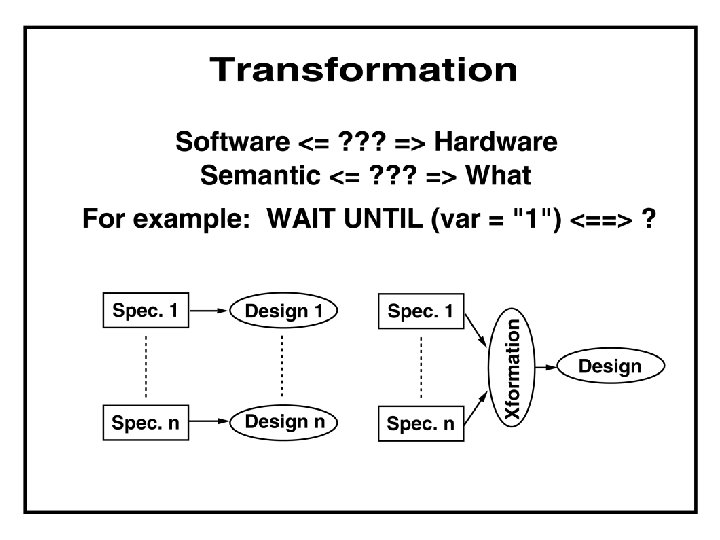
Role of CDFG in High Level Synthesis Behavioral Description This exists in any kind of high level synthesis Parsing CDFG Synthesis Structural RTL Transformation
Design Flow of specialized high level synthesis systems • Synthesizable (and executable) specification • High level verification and design space exploration • Synthesis / estimation / resynthesis • Low level validation • formal • simulation Time-to-market often more important than chip area
Objective function 1 Main goals in classical approach 1. Minimum area • Functional units, registers, memory, interconnect 2. Maximum speed • Number of clock cycles Generally one parameter is set as a constrained and the other one is optimized
More sophisticated Objective functions for high-level and system design Additional goals in modern approaches • More accurate estimation, such as • Size of operands • Sharing of hardware for similar operations (e. g. + and -) • Testability • Low power • Power down, clock disabling • Reliability • Fault tolerance, self-test • Controller
Other steps in HLS • Chaining / multi-cycle operations • Loop pipelining • Retiming • Memory design • Reset, clock • Interface design • Estimation, integration with Logic Synthesis • Real libraries (Higher level components)
Specification issues • Timing I/O operations • Cycle-fixed • Superstate-fixed (pipelined) • Free-floating (order only) • Clocks • Resets • Registered outputs • Loop pipelining
Behavioral Specification Languages • Add hardware-specific constructs to existing languages • Hardware. C • Popular HDL • Verilog, VHDL • Synthesis-oriented HDL • UDL/I
VHDL synthesis tools RTL-synthesis • FU allocation • Limited register allocation • Interconnect allocation • Binding • Logic and physical synthesis Behavioral synthesis • HL Optimizations • Scheduling • RTL-synthesis
Many issues do not exist in FPGA or architectural synthesis that use ready blocks but they exist in VLSI chip design. Chip Synthesis System on a chip Now every stage of synthesis must take space into consideration
Chip synthesis Layout, pins, power, temperature, Reliability, manufacturability, test generation
Layout and partitioning must be considered, must be iterated
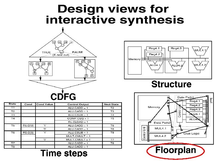
Various models are used in the same synthesis process
Structure to layout
Software engineering
System Synthesis SYSTEM specification for a robot
SYSTEM specification for a robot Several ASIC chips are part of the entire system automatically designed
SYSTEM specification for a robot
Modern Experimental High-Level Synthesis System
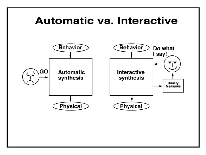
System selects interactively or automatically the realization technology or mixture of them
To allow communication and integration, user’s feedback
System Synthesis System in chip versus system using a chip-set Variants of the robot system
Decomposition is not the same as partitioning System “knows” typical blocks and libraries of commercial components
Example of a System-on-a-Chip Processor Memory Bus Master IP USB Bridge External Memory Interface Wireless UART Everything in one chip – floorplanning and communication
SOC with PLDs Processor Memory Bus Master FPGA USB Bridge External Memory Interface Wireless FPGA Everything in one chip – two FPGAs are inside, reconfigurable dynamically
System Houses/ IC Vendors (Fabless) Library/ IP Vendors (Chipless) EDA Vendors Wafer Foundry Integrators Paradigm Shift Move of EDA vendors to production
Essential Current and Open Issues in Design Automation • Behavioral Specification Languages • • Target Architectures • • On the level of complex operations such as transforms or filters. Allocation/Binding • • For users to exchange, to understand the design better Operation Scheduling • • Network on a chip, sensors and motion control integrated. Intermediate Representation • • From Matlab to chip, from Prolog to chip, etc. On many levels of operations and processors Control Generation • • State machine optimization for large controllers New technologies , integrate FSM-logic-layout Still areas of active research
Future research areas in High Level Syntesis • System level design • Software-hardware system co-design • Reuse • Intellectual Property (IP) or Virtual Components (VC) • More emphasis on verification • currently often > 60% of design effort • correctness by construction
Future Research: IP and Synthesis • Authoring IP for Synthesis • Synthesis utilizing IP • Synthesizing IPs Executable Data Sheets
Executable Data Sheets IP Wrapper IP More than just the Port Interface
Future Directions for system design • Realistic Methodology • Evolutional Transition from Current Practice • Domain Specific • IP-Centric • As both Authoring Aid and Integrator • Software • Co-design and Code Generation Needs better collaboration of research universities and companies
Literature [1] D. Gajski and N. Dutt, High-level Synthesis : Introduction to Chip and System Design. Kluwer Academic Publishers, 1992. [2] G. D. Micheli, Synthesis and Optimization of Digital Circuits. New York : Mc. Graw Hill. Inc, 1994. [3] A. P. Chandrakasan, S. Sheng, and R. W. Brodersen, "Low-Power CMOS digital design", IEEE J. of Solid-State Circuits, pp. 473 -484, 1992. [4] A. P. Chandrakasan, M. Potkonjak, R. Mehra, J. Rabaey, and R. W. Brodersen, "Optimizing power using transformation, " IEEE Tr. on CAD/ICAS, pp. 12 -31, Jan. 1995. [5] E. Musool and J. Cortadella, "Scheduling and resource binding for low power", Int'l Symp on Synstem Syntheiss, pp. 104 -109, Apr. 1995. [6] Y. Fang and A. Albicki, "Joint scheduling and allocation for low power, " in Proc. of Int'l Symp. on Circuits & Systems, pp. 556 -559, May. 1996. [7] J. Monteiro and Pranav Ashar, "Scheduling techniques to enable power management", 33 rd Design Automation Conference, 1996. [8] R. S. Martin, J. P. Knight, "Optimizing Power in ASIC Behavioral Synthesis", IEEE Design & Test of Computers, pp. 58 -70, 1995. [9] R. Mehra, J. Rabaey, "Exploting Regularity for Low Power Design", IEEE Custom Integrated Circuits Conference, pp. 177 -182. 1996. [10] A. Chandrakasan, T. Sheng, and R. W. Brodersen, "Low Power CMOS Digital Design", Journal of Solid State Circuits, pp. 473 -484, 1992. [11] R. Mehra and J. Rabaey, "Behavioral level power estimation and exploration, " in Proc. of Int'l Symp. on Low Power Design, pp. 197 -202, Apr. 1994. [12] A. Raghunathan and N. K. Jha, "An iterative improvement algorithm for low power data path synthesis, " in Proc. of Int'l Conf. on Computer-Aided Design, pp. 597 -602, Nov. 1995. [13] R. Mehra, J. Rabaey, "Low power architectural synthesis and the impact of exploiting locality, " Journal of VLSI Signal Processing, 1996.
[14] M. B. Srivastava, A. P. Chandrakasan, and R. W. Brodersen, "Predictive system shutdown and other architectural techniques for energy efficient programmable computation, " IEEE Tr. on VLSI Systems, pp. 42 -55, Mar. 1996. [15] A. Abnous and J. M. Rabaey, "Ultra low power domain specific multimedia processors, " in Proc. of IEEE VLSI Signal Processing Workshop, Oct. 1996. [16] M. C. Mcfarland, A. C. Parker, R. Camposano, "The high level synthesis of digital systems, " Proceedings of the IEEE. Vol 78. No 2 , February, 1990. [17] A. Chandrakasan, S. Sheng, R. Brodersen, "Low power CMOS digital design, ", IEEE Solid State Circuit, April, 1992. [18] A. Chandrakasan, R. Brodersen, "Low power digital CMOS design, Kluwer Academic Publishers, 1995. [19] M. Alidina, J. Moteiro, S. Devadas, A. Ghosh, M. Papaefthymiou, "Precomputation based sequential logic optimization for low power, " IEEE International Conference on Computer Aided Design, 1994. [20] J. Monterio, S. Devadas and A. Ghosh, "Retiming sequential circuits for low power, " In Proceeding of the IEEE International Conference on Computer Aided Design, November, 1993. [21] F. J. Kurdahi, A. C. Parker, REAL: A Program for Register Allocation, : in Proc. of the 24 th Design Automation Conference, ACM/IEEE, June. pp. 210 -215, 1987. [22] A. Wolfe. A case study in low-power system level design. In Proc. of the IEEE International Conference on Computer Design, Oct. , 1995. [23] T. D. Burd and R. W. Brothersen. Energy ecient CMOS micropro-cessor design. In Proc. 28 th Annual Hawaii International Conf. On System Sciences, January 1995. [24] A. Dasgupta and R. Karri. Simultaneous scheduling and binding for power minimization during microarchitectural synthesis. In Int. Symposium on Low Power Design, pages 69 -74, April 1995. [25] R. S. Martin. Optimizing power consumption, area and delay in behavioral synthesis. Ph. D thesis, Department of Electronics, Faculty of Enginering, Carleton University, March 1995. [26] A. Matsuzawa. Low-power portable design. In Proc. International Symposium on Advanced Research in Asynchronous Circuits and Systems, March 1996. Invited lecture. [27] J. D. Meindl. Low-power microelectronics: retrospect and prospect. Proceedings of the IEEE 83(4): 619 -635, April 1995.
Exam Problem 1 • • Write set of equations for solving some type of equations by an iterative method Find Data Flow Graph for this set of equations Schedule Allocate Bind and share Design final data path Find control unit Optimize partitioning and communication • • Too long for one exam. Can be a take-home exam •
Exam Problem 2 1. Allocate to time 2. Allocate to logic blocks 3. Design a complete controller 4. Design a controller for pipelined design
Exam Problem 3: Scheduling • Set area constraint • 2 multipliers • 2 general-purpose ALUs • Set the cycle time = latency of a multiplier • Goal: minimize latency of circuit
Exam Problem 4 1. Give the set of functional resources: two multipliers, two ALUs. 2. Scheduling example with the constraints (two set constraints, then optimize third) 3. We need to maintain the data dependencies. (e. g. vertex 6 must be scheduled at least one cycle after vertex 1. ) 4. This is the same differential equation dataflow graph from a previous slide. 5. Edges that are not necessary to !show dependencies between vertices have been removed. 6. Complete this problem
Exam Problem 5: Binding
Exam Problem 5
Second Exam Problem 5: Competition for Students 1. The student with the smallest area gets a prize, the student with the smallest latency gets a prize. 2. Bring exam submission to the next lecture to be eligible for competition. year his rt o f t o N 3. You are not required to give an optimal solution, since that may prove to be more difficult than can be done in a reasonable amount of time.