Arc Welding Equipment By Layne Taylor Advances in

Arc Welding Equipment By Layne Taylor

Advances in Welding Technology

Welder Power Source Classifications b There are two main ways welding power can be supplied. b Constant Voltage b Constant Current

Constant Voltage b The arc voltage remains constant at the selected setting even if the amperage increases or decreases. b This type of power source is used primarily in Gas Metal Arc Welding (Mig Welding). b The constant arc voltage helps the welder maintain a constant arc length. To change the arc length the voltage settings must be changed.

Constant Voltage b Constant voltage power sources have the ability to self adjust to maintain a constant arc length. b By moving the gun closer to the work the machine will deliver more current and melt the rod off faster. b By moving the gun farther from the work the machine will deliver less current so the electrode will burn slower. b In this way the arc length remains fairly constant.

Constant Current Power Sources b The amount of watts consumed remains constant while voltage output will decrease as amperage increases. b This is the type of power source used in arc welding & TIG welding processes. b Why?

Constant Current Power Sources b This power source provides a high open circuit voltage before the arc is struck. Which makes it easier to strike the arc. The high open circuit voltage quickly stabilizes the arc. The arc voltage rapidly drops to the closed circuit level after the arc is struck. Following this short starting surge the power (Watts) remains almost constant despite the changes in arc length.

Constant Current Power Sources b This type of current allows the welder to control the molten pool and electrode melting rate by making small changes in arc length. This control is very important when welding in the vertical and overhead welding positions.

Welder Transformers b What is a transformer? b An device that alters or changes the properties (volts & Amps) of the electrical current. b Where are transformers used? b Electrical Power lines b Electrical sub stations b engine coils b Welders

Welder Transformers b There are two types of electrical transformers. b Step Down transformers b Step Up transformers

The Step Down Transformer b The step down transformer is the type of transformer used in welding machines today. b The step down transformer converts high voltage low amperage into lower voltage higher amperage required for welding. b How does it work?

The Step Down Transformer Components b There are two separate sets of windings separated by an Iron core. b The primary windings are made using thinner wire with more windings. b The secondary windings use a larger wire with fewer windings

The Step Down Transformer b The primary windings are smaller because less amperage is flowing through the wire. b By winding the wire the magnetic field created by electron flow is more concentrated producing a much stronger central magnetic force.

The Step Down Transformer b Because the current being used is alternating the magnetic field is constantly being built and then collapsed. b By placing a secondary winding in the magnetic field created by the primary winding each time the current collapses current will be induced in the secondary winding.

The Step Down Transformer b By placing an Iron core between the primary and secondary windings the concentration of the magnetic field increases even further. b Because the wire is larger in the secondary winding with fewer wraps more current (amperage) is produced at a lower voltage.

Step Up Transformer b A step up transformer steps up the voltage while stepping down the amperage. b A engine coil is a good example of a step up transformer. b An engine coil converts the amperage produced in the primary circuit of the engine coil into higher voltage in the secondary circuit needed to jump the spark plug gap. b The windings on a step up transformer are opposite of a step down transformer.

Adjusting the Amperage b There are primarily three ways of adjusting the output of amperage created by the transformer b Tapping into the secondary windings at different locations b Moving the iron core closer to or further away from the windings. b Moving the windings closer together or further apart.

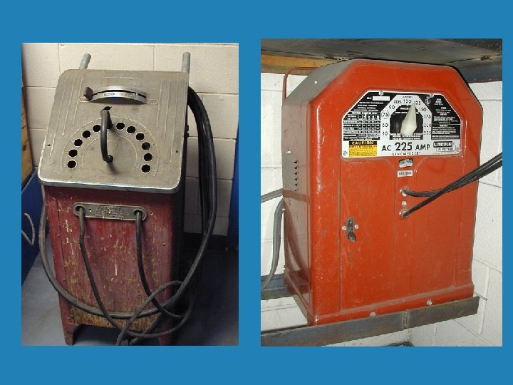
Types of Welding Transformers

Tapping Into The Secondary Windings b The adjustment may be made by physically unplugging and plugging in the welding leads at different intervals. b Or by moving a dial which touches different contact points within the secondary windings.

Movable Coil Welder

Movable Coil / Core Welder

The Inverter Welder b How can you produce more current in a welder Transformer? • • • More windings Larger wire diameter A larger iron core A stronger magnet field Have the magnetic field pass the windings faster b All but one of these methods adds size and weight to the welder. Which one does not?

The Inverter Welder b Inverter welders use less input power with a higher efficiency level. b They are often designed to provide multiple process capabilities. b The inverter welder uses solid state electronic parts to change the frequency of the current from 60 cycle current to a range from 1000 to 50, 000 Hz. b This frequency increase allows the transformer to be reduced by up to 70% in size.

Welder Duty Cycle b The percentage of time in minutes that a welder can weld without overheating. b Most Arc welders have a 20 - 40% duty cycle. b Most Mig Welders have a 40 – 60% duty cycle. b 20% duty cycle = 12 minutes in an hour b 40% duty cycle = 24 minutes in an hour b 60 % duty cycle = 36 minutes in an hour
- Slides: 25