Arc Objects is the development platform for the

Arc Objects is the development platform for the Arc. GIS family of applications such as Arc Map, Arc Catalog, and Arc Scene. Arc Objects is a framework that lets you create domain-specific components from other components. Arc Objects provides an infrastructure for application customization that lets you concentrate on serving the specific needs of your clients.

ARCOBJECTS AND THE ARCGIS DESKTOP n n Arc. Objects is the development platform for Arc GIS Desktop. The Arc GIS Desktop systems each contain a configuration of applications, such as Arc Catalog, Arc Map, Arc Toolbox, and Arc Scene, and can host a variety of extension products such as Arc. GIS Spatial Analyst, Arc. GIS Geostatistical Analyst, Arc. GIS 3 D Analyst and others.

Arc Map , Arc Catalog n Arc Map is used for mapping and editing tasks as well as map-based analysis. n Arc Catalog is used for managing your spatial data holdings, defining your geographic data custom schemas, and recording and viewing metadata.
 technology.")
ARCOBJECTS FRAMEWORK n Arc Objects is built using Microsoft’s Component Object Model (COM) technology. n It is possible to extend Arc Objects by writing COM components using any COM-compliant development language. n You can extend every part of the Arc Objects architecture in exactly the same way as ESRI developers do.

Interpreting object model diagrams n n n Arc Objects object model diagrams are based on the UML notation, an industry-diagramming standard for object-oriented analysis and design. The development environment, Visual Basic or other, lists all of the many classes and members but does not show the structure of those classes. These diagrams complete your understanding of the Arc Objects components.

Classes and objects There are 3 types of classes shown in the UML diagrams —abstract classes, co classes, and classes. § A coclass represents objects that you can directly create using the object declaration syntax in your development environment. In Visual Basic, this is written with the Dim p. Foo As New Foo. Object syntax. n A class cannot directly create new objects, but objects of a class can be created as a property of another class or by functions from another class. Eg. Feature. Cursor n An abstract class cannot be used to create new objects, but it is a specification for subclasses. Eg: “line” could be an abstract class for “primary line” and “secondary line” n

Type inheritance n Type inheritance defines specialized classes that share properties and methods with the super class and have additional properties and methods. Line Primary Line Secondary Line This diagram shows that a primary line (creatable class) and secondary line (creatable class) are types of a line (abstract class).

Instantiation n Instantiation specifies that one object from one class has a method with which it creates an object from another class. Pole Transformer A pole object might have a method to create a transformer obje

Customization n Showing and hiding toolbars using the Customize dialog box 1. Click the Tools menu and click Customize. The Customize dialog box appears. You can also double-click any unoccupied area of any toolbar to display the Customize dialog box. 2. If it is not visible, click the Toolbars tab. The presence or absence of a check mark next to the toolbar name indicates its visible state. 3. Check and uncheck the check boxes.

Creating a new toolbar n n n In the Toolbars tab of the Customize dialog box, click New. In the dialog box that appears, specify Chapter One Examples as the name of the new toolbar or use the default setting. Store the toolbar in the document by changing the name of the Save in dropdown list from Normal. mxt to Untitled or the name of the current project. Click OK. The newly created toolbar appears near the top of the application window.

Adding buttons to a toolbar n n n n Make sure the toolbar you just created is visible. If it is not visible, display the Customize dialog box. Click the Commands tab of the Customize dialog box. Select the Pan/Zoom category from the Categories list. Scroll to the bottom of the Commands list. Select the Zoom in command drag it to the toolbar. Release the command when the arrow cursor with a small box below it appears. Continue adding commands from the Pan/Zoom category You may switch to other categories to select commands.

Renaming a toolbar n n n In the Toolbars tab, click the name of the toolbar whose name you want to change. Click the Rename button. In the dialog box that appears, specify My Own Tools as the new name. Note that you can only rename toolbars you’ve created. Click OK. If you decide not to rename the toolbar, click Cancel.

Removing buttons from a toolbar n n Make sure the toolbar you just renamed, My Own Tools, is visible. If it is not visible, display the Customize dialog box. Drag some of the commands off the toolbar. Even though you’ve removed the buttons from the toolbar, they are still available in the Customize dialog box.

Adding a menu to a toolbar n n n n Make sure the My Own Tools toolbar is visible. If it is not visible, display the Customize dialog box. Click the Commands tab and choose the Menus category from the Categories list on the lefthand side of the dialog box. In the Commands list at the right-hand side of the dialog box, click Selection. Drag and drop it to the left of the Zoom In button on the My Own Tools toolbar. Click Close in the Customize dialog box. Click Selection on the My Own Tools toolbar and note the menu that appears.

Saving changes to a template n n n You can save your work to a document or template. Changes saved to a document are specific to the document, whereas changes saved to a template will be reflected in all documents based on the template. Click the File menu and click Save As. Navigate to the Templates folder of the <installation directory>bin folder. Click the Create New Folder button. Type a new name for the folder and double-click it. Type the template name, click Arc. Map Templates (*. mxt) from the Save as type dropdown menu, then click Save.

WRITING MACROS IN VBA n n You can use the VBA integrated development environment to create macros to help you automate tasks you perform repeatedly or to extend the application’s built-in functionality. With the Visual Basic Editor, you can edit macros, copy macros from one module to another, rename the modules that store the macros, or rename the macros.

Creating a macro n n n n Click the Tools menu, point to Macros, then click Macros. In the Macros dialog, type name in the Macro name text box and click Create. The application creates a new module named Module 1 and stubs in the Sub procedure. Enter some code. Switch back to Arc. Map by clicking the File menu, clicking Close, and clicking Return to Arc. Map. Click the Tools menu, point to Macros, then click Macros. Select the Module 1. Name macro and click Run.

Adding a macro to a toolbar n n n Click the Tools menu and click Customize. In the Toolbars tab, ensure that the toolbar is visible. Click the Commands tab and select the Macros category. Click the name of project in the Save in dropdown menu. The commands list to the right of the dialog box lists Project. Module 1. Name. Drag the macro name to the toolbar you created. The macro appears with a default icon. To change its properties, right-click the icon. In the context menu that appears, click Change Button Image and choose a button from the palette of icons. Close the Customize dialog box. Click the button to run the macro.

Calling built-in Commands n n n Calling existing commands involves working with the Arc. ID module. Using the Find method, the code locates the unique identifier (UID) of the command in the Arc. ID module. Steps 1. Click the Tools menu, point to Macros, then click Visual Basic Editor. 2. In the Module 1 module, create a Sub procedure with the following code: 3. Add the macro to a toolbar or menu. 4. Run the macro.
 Dim int. Ans As Integer Dim")
Code for Full. Extent Sub Full. Extent. Plus() Dim int. Ans As Integer Dim p. Item As ICommand. Item With This. Document. Command. Bars Set p. Item =. Find(Arc. ID. Pan. Zoom_Full. Extent) p. Item. Execute int. Ans = Msg. Box(“Zoom to previous extent? ”, vb. Yes. No) If int. Ans = vb. Yes Then Set p. Item =. Find(Arc. ID. Pan. Zoom_Zoom. To. Last. Extent. Back) p. Item. Execute End If End With End Sub

Creating a Command in VBA n n n n Once invoked, a command usually performs some direct action without user intervention. A command is a type of UIControl. Click the Tools menu and click Customize. In the Customize dialog box, click the Commands tab and change the Save in dropdown menu to the name of your project or to Untitled. In the Categories list, select UIControls. Click New UIControl. In the dialog box that appears, choose UIButton. Control as the UIControl Type, then click Create and Edit.

Adding code for the UIControl n n The application adds an entry in the Object Box for the UIButton. Control and stubs in an event procedure for the UIButton. Control’s Click event. You’ll add code to this event to zoom the display to the extents of the dataset. Private Sub UIButton. Control 1_Click() Dim p. Doc As IMx. Document Set p. Doc = This. Document p. Doc. Active. View. Extent =p. Doc. Active. View. Full. Exte p. Doc. Active. View. Refresh End Sub

Adding code for the UIControl n n Click the Tools menu, click Customize, then click the Commands tab. In the Customize dialog box, click the Commands tab and change the Save in dropdown menu to the name of your project or to Untitled. In the Categories list, choose UIControls and drag the UIButton. Control you created to a toolbar. Close the Customize dialog box. Try the new command by zooming in on the map and clicking the button.

Creating a tool in VBA n n n 1. Click the Tools menu and click Customize. 2. Click the Commands tab and change the Save in combo box to the name of your project or Untitled. 3. Choose UIControls from the Categories list. 4. Click New UIControl. 5. In the dialog box that appears, choose UITool. Control as the UIControl Type, then click Create and Edit.

Changing button properties n n Right-click any toolbar and click Customize in the context menu that appears. Click the right mouse button to determine whether a context menu is available. Right-click the button whose properties you want to change. In the context menu that appears, click Change Button Image and choose an image. The image you chose appears on the face of the button. Close the Customize dialog box.

Thank you. .

Arc Objects Problem Solving Guide n DEFINE THE ARCOBJECTS PROGRAMMING TASK 1. Describe the problem in Arc Objects terms. 2. Identify subtasks. 3. Decide where to write the code. 4. Search for a related sample or recommended methodology. n LOCATE THE CORRECT OBJECT MODEL 1. Identify a subtask. 2. Extract keywords. 3. Search for the correct object model diagrams. 4. Review all related documentation. n NAVIGATE THE OBJECT MODEL DIAGRAM 1. Review the structure of the object model diagram.

Writing Code Using Arc Objects n In general, there are three ways to write Arc Objects code: • As a VBA macro in an Arc. GIS application • As an Active. X COM component such as a DLL or OCX • As a standalone EXE

Writing VBA macros in Arc. GIS n Advantages • It’s fast and easy to create, test, and debug macros inside Arc Map and Arc Catalog. • The standard ESRI type libraries are already referenced. • Important global variables, such as the Application and Document, are available. • It’s simple to assemble UI forms using VBA and Active. X components. • It’s straightforward to integrate VBA code with new Arc Objects UIControls. • It’s relatively easy to migrate VBA code to VB Active. X DLL projects.

Writing Active. X COM components n n Advantages • They can be easily delivered to end users via custom setup programs. • You can hide Arc Objects code in a binary file and then deliver the functionality to end users with a setup program. • You can extend and customize virtually every aspect of the Arc. GIS technology. Disadvantages • Have to acquire and use another COM-compliant development tool • Do not have direct access to the Application and This. Document global variables. • It is often more difficult to debug the code.

Standalone Applications n n Advantages • You can use the ESRI Arc Objects Map control to simplify the embedding of Arc Objects functionality in your application. • You can design a highly customized user interface specific to your application. • You can quickly create small, lightweight applications. Disadvantages • You cannot take advantage of the extensive functionality that ESRI has built into the existing Arc. GIS applications such as Arc Map or Arc Catalog. • You cannot use Arc Map documents or templates to their fullest capacity.

Arc Map Core Objects

Arc Map Document

APPLICATION COCLASS n n The Application object directly manages a collection of objects, Mx. Document, App. Display, Selection. Environment. When you first start Arc Map, the Application object is first created, and then it in turn instantiates all of the objects it manages. The IApplication interface provides access to the Mx. Document object, the Status. Bar object, the Templates object, the currently selected tool, the Visual Basic Editor. The IMx. Application interface provides access to the remainder of the objects the Application automatically creates, including App. Display, Paper Co Class, Printer, and Selection. Environment. Additionally, IMx. Application exposes methods for exporting the current map document or copying it to the system clipboard.
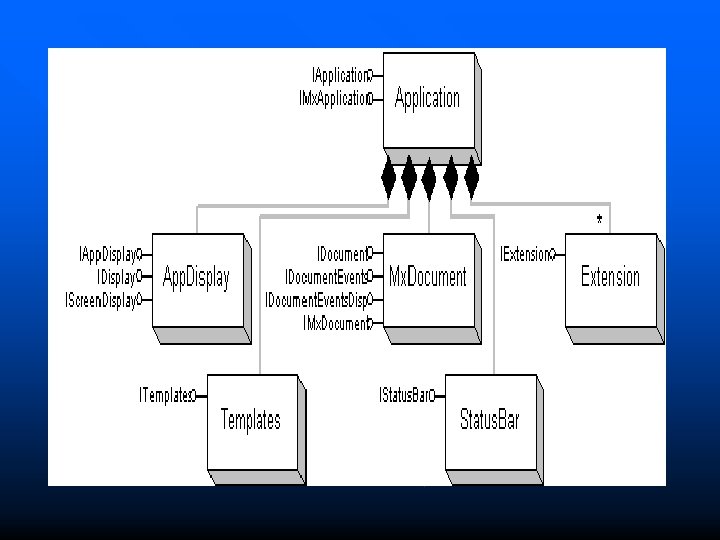

MXDOCUMENT COCLASS n n The Arc Map document is called Mx. Document; its role is to control the representation of data. The Arc Map application automatically creates this object when the application first starts. Mx. Document specifically creates and manages the following objects: an empty Map, a Page. Layout, the TOCCatalog. View, the TOCDisplay. View. You can obtain a reference to the Mx. Document through IApplication: : Document.

Views n n n View is the main application window, or the place where all data is drawn. Arc Map currently has two different views, data view and layout view Objects implement the IActive. View interface to establish themselves as views. The data view corresponds to a Map object, and the layout view corresponds to the Page. Layout object. Either of these objects can be set as the document’s active view, and only one view is visible at a time.

Checking Type of View n The following VBA code checks the type of active view: Dim p. Mx. Doc As IMx. Document Set p. Mx. Doc = Application. Document If Type. Of p. Mx. Doc. Active. View Is IMap Then Msg. Box "Active View is a Map" Else. If Type. Of p. Mx. Doc. Active. View Is IPage. Layout Then Msg. Box "Active view is the Page. Layout" End If

Application Extensions n n The Application object directly manages the life of all application extensions. Application extensions are those extensions registered in the ESRI Mx. Extension objects; All extensions are automatically created and destroyed in synchronization with an Application object. Use the IExtension interface to query the properties of an extension or implement this interface to create your own custom extension.
 Dim p. Editor As")
Getting Reference to an Extension Public Sub Check. Edit. State() Dim p. Editor As IEditor Dim p. UID As New UID p. UID = "esri. Core. Editor" Set p. Editor = Application. Find. Extension. By. CLSID(p. UID) If p. Editor. Edit. State = esri. State. Editing Then Msg. Box "Active Edit Session Present" End If End Sub

TOCDISPLAYVIEW AND TOCCONTENTSVIEW COCLASSES n n Contents views are tabs in the Arc Map table of contents. Arc. Map ships with two contents views: display view and source view. The Display tab is the TOCDisplay. View object, and the Source tab is the TOCCatalog. View object. Developers can add new contents views by creating their own custom object that implements the IContents. View interface.

MAP COCLASS n n n Every map document contains at least one Map object. Only one Map can have focus at a time, and this Map is called the focus map. IMx. Document provides access to all of the Map objects loaded in the document; IMx. Document: : Focus. Map returns a reference to the Map currently with focus, and IMx. Document. Maps returns the entire collection of Map objects. Map. Surround objects are elements that are related to a Map. Types of map surrounds include

SELECTIONENVIRONMENT COCLASS n n n Controls properties related to creating and drawing selections. A Selection. Environment object is automatically created by the Application object when the application starts. Access to the Application object’s Selection. Environment is through IMx. Application: : Selection. Environment.
 Dim p. Mx. Doc")
Change Default Selection Color Public Sub Change. Default. Selection. Color() Dim p. Mx. Doc As IMx. Document Dim p. Mx. App As IMx. Application Dim p. Selection. Env As ISelection. Environment Dim p. Rgb. Color As IRgb. Color Set p. Mx. App = Application 'QI Set p. Mx. Doc = Application. Document Set p. Selection. Env = p. Mx. App. Selection. Environment Set p. Rgb. Color = New Rgb. Color p. Rgb. Color. Red = 255 Set p. Selection. Env. Default. Color = p. Rgb. Color

Display Objects FEATURE RENDERER A feature renderer is a method for drawing feature layers. Use symbols and colors to visually display features, possibly based on one or more attributes. Types of feature renderers: • Simple. Renderer uses the same symbol for each feature. • Class. Breaks. Renderer allows classes of numeric attribute values to be defined. A different symbol is specified for each class. • Unique. Value. Renderer uses a different symbol for each unique attribute value. • Proportional. Symbol. Renderer modifies the size of the symbol in proportio to an attribute from a field. • Dot. Density. Renderer displays a scattering of marker symbols in polygon features, the density of which reflects the value of an attribute. • Chart. Renderer displays pie, bar, or stacked bar charts that are comprised from one or more attribute fields.

Get a Feature Renderer n To get to a feature renderer object in Arc Map from a layer, QI to IGeo. Feature. Layer and get the Renderer property. n A simple renderer is the default renderer object when a new feature class is loaded. n ' Check if the layer is a feature layer If Not Type. Of p. Layer Is IGeo. Feature. Layer Then Exit Sub Set p. Geo. Feature. Layer = p. Layer n ' Check if there is a simple renderer and get a reference to it If Not Type. Of p. Geo. Feature. Layer. Renderer Is ISimple. Renderer Then Exit Sub Set p. Simple. Renderer = p. Geo. Feature. Layer. Renderer

Color Objects n n Objects that support the IColor interface allow precise control over any color used within the Arc. Objects model. You can get and set colors using a variety of standard color models—RGB, CMYK, HSV, HLS, and Grayscale. RGBCOLOR COCLASS To get and set the red, green, and blue components of a color Interface- IRGBColor CMYKCOLOR COCLASS Colors can be specified for output in terms of Cyan, Magenta, Yellow, and Black. Interface- ICMYKColor

Symbol Objects

Types of Symbols n Arc. Objects uses three categories of symbols to draw geographic features: n Marker symbols, Line symbols, Fill symbols. n n

Display Objects

Display Objects n n Allow application developers to easily draw graphics on a variety of output devices. Allow you to render shapes stored in real-world coordinates to the screen, the printer, and export files. Use the IDisplay interface to draw points, lines, polygons, rectangles, and text on a device. Access to the display object’s Display. Transformation object is provided by this interface.

To Pan Map Display Private Sub UITool. Control 1_Mouse. Down(By. Val button As Long, _By. Val shift As Long, By. Val x As Long, By. Val y As Long) Dim p. Screen. Display As IScreen. Display Dim p. Active. View As IActive. View Dim p. Mx. Doc As IMx. Document Set p. Mx. Doc = Application. Document Set p. Active. View = p. Mx. Doc. Focus. Map Set p. Screen. Display = p. Active. View. Screen. Display p. Screen. Display. Track. Pan End Sub

DISPLAYTRANSFORMATION COCLASS n n Manages the map-to-device transformation Defines how real-world coordinates are mapped to an output space. Map’s Display. Transformation has a Spatial. Reference object that manages the Map’s current coordinate system. A reference to the Spatial. Reference object is set through IDisplay. Transformation: : Spatial. Reference.

IDisplay. Transformation To prepare a transform for use, follow these steps: 1. Set the full map extent with the Bounds property. 2. Set the visible map extent (zoom rectangle) with the Visible. Bounds property. 3. Set the output area of the device using the Device. Frame property. 4. Set the resolution of the output device using the Resolution property. n

Rubber Band Objects

IRubber. Band Interface n n n IRubber. Band interface, allow the user to digitize geometries on the display using the mouse—either to create whole new geometry objects or to update existing ones. Examples-Dragging an envelope, forming a new polyline, or moving a point. IRubberband interface has two methods Track. Existing Move existing geometries Track. New Create new geometries

Track. New method Private Sub UITool. Control 1_Mouse. Down(By. Val button As Long, _ By. Val shift As Long, By. Val x As Long, By. Val y As Long) Dim p. Rubber. Line As IRubber. Band Dim p. Geom As IGeometry Dim p. MXDoc As IMx. Document Set p. MXDoc = This. Document Set p. Rubber. Line = New Rubber. Line Set p. Geom=p. Rubber. Line. Track. New p. MXDoc. Active. View. Screen. Display, Nothing) End Sub
- Slides: 57