Applications of the 3 D electromagnetic model to


 dielectrics and/or conductors: –")


 reordering – Precondition • ILUTP(incomplete LU threshold")


- Slides: 26
Applications of the 3 D electromagnetic model to some challenging optical problems September 24, 2004 Xiuhong wei, Paul Urbach, Arther Wachters Supported by the Dutch Ministry of Economic Affairs under project TS 01044
• Configurations – 2 D or 3 D – Non-periodic structure (Isolated pit in multilayer) – Periodic in one direction (row of pits) – Periodic in two directions (bi-gratings) – Periodic in three directions (3 D crystals) • Source – Unrestricted incident field (plane wave, focused spot) – Imposed current density
• Materials – Linear. – In general anisotropic, (absorbing) dielectrics and/or conductors: – Magnetic anisotropic materials (for completeness): – Materials could be inhomogeneous:
• Mathematical Model – Given field: incident field imposed current – Total field: – Maxwell equations’ are equivalent to Vector Helmholtz Equation: – Scattered field: – The scattered field satisfies the Sommerfeld radiation condition.
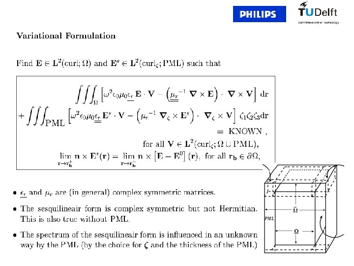
• Variational formulation – E=E 0+Es
iz k j • Calculate E 0 in Multilayer – S-polarization, i – P-polarization, j – is the source term – Tangential field h(z), e(z) in basis (i, l) i l
– Up and down recursion – Amplitude for planewave – Where are the tangential source term.
• Numerical calculation – Construction of Matrix – Matrix property • Complex symmetric • indefinite
• Iterative solver – RCM(reversing Cuthill-Mckee) reordering – Precondition • ILUTP(incomplete LU threshold pivoting) – to solve a problem with 300, 000 unknows, a fill-in is needed of more than 600, which takes about 25 hours on a Hewlett Packard machine (CPU = 107 FLOPS/sec). . • Compare with MRILU(Matries reordering ILU) – More suitable for Finite Difference Method – Complex problems give an extra complication – Krylov subspace method: BICGSTAB (biconjugate gradient stabilized algorithm )
• Propagation outside of computational domain – The field of Electric Dipole in free space – However we need the field of electric dipole in Multilayer • Calculated by Fourier transformation plane wave expansion • Using recursion as for calculating E 0
• Stratton-Chu formula Observation point
• Results: Near Field Optical Recording • Background • Geometry In the SIL: kx n. SIL kx Hence, Saptially frequences of the spot are increased , which means the spot became smaller /2 n. SIL Cross section
• = 405 nm • NAeffective= 1. 9 • Spotsize /2 NAeff=106 nm • Grooves(track) Track pitch=226 nm Top view
Top view Energy density, wall angle 55, E // groove Energy density , wall angle 55, E groove
Top view Energy density, wall angle 85, E //groove Energy density , wall angle 85, E groove
Cross section xz-plane Energy density, wall angle 55, E//groove Energy density , wall angle 55, E groove
Cross section yz-plane Energy density, wall angle 55, E // groove Energy density , wall angle 55, E groove
– Lithography • Background • Geometry Incoherent Light source Condenser Mask Aperture stop Projection lens Photoresist wafer
• • • Material: Crome = 193 nm High NA lithography n. Cr=0. 86 + 1. 65 I 100 nm Perpendicular incident planewave 260 nm 720 nm 340 nm
Top view Square mask, E Serif mask, E
Top view Square mask, E
Top view Square mask, finite conduct, E Perfect conduct, E
Cross section yz-plane Square mask, finite conduct, E Perfect conduct, E
Far field Square mask, E
acknowledge • Our cluster in Philips, Paul Urbach, Arthur wachters, Jan Veerman • Delft mathematical department, Kees Vuik, Kees Oosterlee, Yogi Erlangga, Mari Berglund • Shell staffs, Ren´e-Edouard Plessix, Wim Mulder