Appendix D The ARM Processor Appendix Outline Memory


![Addressing modes • Pre-indexed mode: LDR Rd, [Rn, #offset] performs Rd ← [[Rn] +](https://slidetodoc.com/presentation_image_h/204cc93370ef85f9b28983a993d49ce1/image-13.jpg "Addressing modes • Pre-indexed mode: LDR Rd, [Rn, #offset] performs Rd ← [[Rn] +")
![Addressing modes • Relative mode: LDR Rd, ITEM performs Rd ← [[PC] + offset]](https://slidetodoc.com/presentation_image_h/204cc93370ef85f9b28983a993d49ce1/image-14.jpg "Addressing modes • Relative mode: LDR Rd, ITEM performs Rd ← [[PC] + offset]")
: LDR Rd,")
![Addressing modes • Post-indexed mode (a generalization of the autoincrement mode): LDR Rd, [Rn],](https://slidetodoc.com/presentation_image_h/204cc93370ef85f9b28983a993d49ce1/image-16.jpg "Addressing modes • Post-indexed mode (a generalization of the autoincrement mode): LDR Rd, [Rn],")


![Instructions • Arithmetic: MUL R 0, R 1, R 2 performs R 0←[R 1]](https://slidetodoc.com/presentation_image_h/204cc93370ef85f9b28983a993d49ce1/image-28.jpg "Instructions • Arithmetic: MUL R 0, R 1, R 2 performs R 0←[R 1]")

![Instructions • Move: MOV Rd, Rm performs Rd ← [Rm] MOV Rd, #value performs](https://slidetodoc.com/presentation_image_h/204cc93370ef85f9b28983a993d49ce1/image-30.jpg "Instructions • Move: MOV Rd, Rm performs Rd ← [Rm] MOV Rd, #value performs")
![Instructions • Move: MVN Rd, Rm or #value loads the bit-complement of [Rm] or](https://slidetodoc.com/presentation_image_h/204cc93370ef85f9b28983a993d49ce1/image-31.jpg "Instructions • Move: MVN Rd, Rm or #value loads the bit-complement of [Rm] or")


![Instructions • Compare: CMP Rn, Rm performs [Rn] - [Rm] and updates condition code](https://slidetodoc.com/presentation_image_h/204cc93370ef85f9b28983a993d49ce1/image-37.jpg "Instructions • Compare: CMP Rn, Rm performs [Rn] - [Rm] and updates condition code")


 3. The combination of the instruction LDR R 2,")


- Slides: 53
Appendix D The ARM Processor
Appendix Outline • • • Memory organization Characteristics of the ARM ISA Register structure and addressing modes Instructions and assembly language Operating modes and exceptions Input/output
Memory organization Byte-addressable, 32 -bit address space Little- or big-endian addressable 32 -bit word length Word, half-word, and byte data transfers to and from processor registers • Word and half-word transfers must be aligned • •
Instruction set characteristics • RISC-style aspects: All instructions 32 bits long Only Load and Store instructions access memory Arithmetic and logic instructions operate on processor register contents
Instruction set characteristics • CISC-style aspects: Autoincrement, autodecrement, and PC-relative addressing modes provided Condition codes used for conditional execution of instructions Multiple word Loads and Stores implemented with single instructions
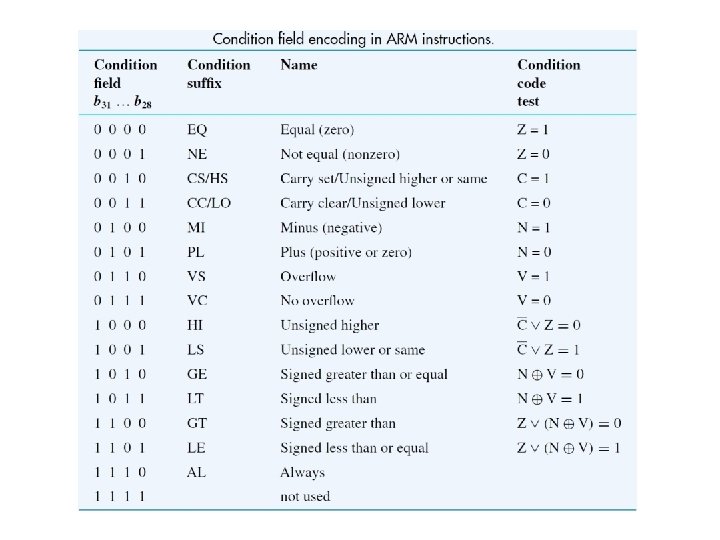
Unusual aspects of the ISA • Conditional execution of instructions: All instructions, including branches, are executed conditionally, based on a 4 -bit condition field value in each instruction • No explicit shift instructions; but one operand of an operation can be preshifted • Many multiply instructions, but no divide instructions
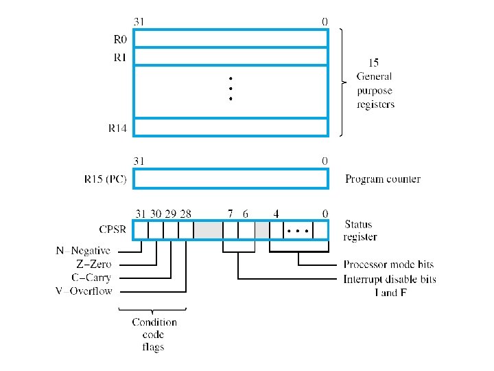
Register structure • Sixteen 32 -bit processor registers, labeled R 0 through R 15 • Register R 15 is the program counter (PC) • Registers R 13 and R 14 have dedicated uses related to subroutine and processor stack management • A status register (CPSR) holds the condition code flags (N, Z, C, V), two interruptdisable bits, and five processor mode bits
Banked registers • Duplicates of some of the registers in the range R 8 through R 14 are provided for each of the processor modes other than the User and System modes • Banked registers make context switches between the modes more efficient by avoiding register save/restore operations on such switches
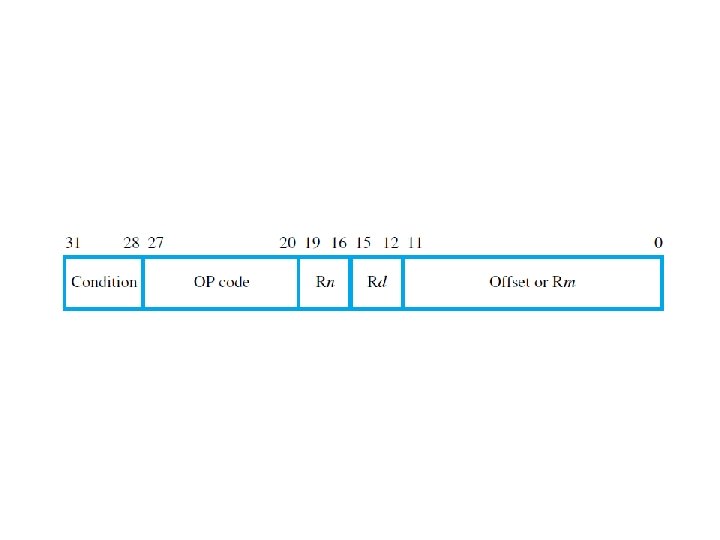
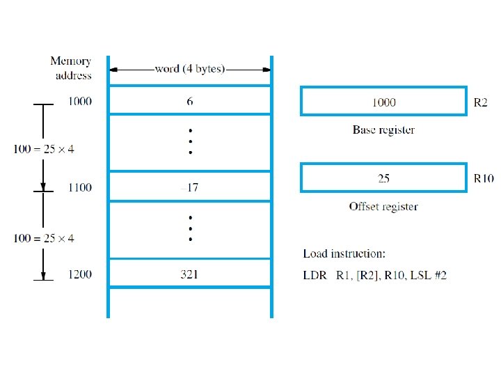
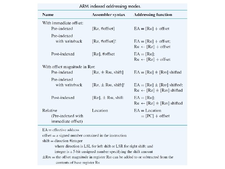
Addressing modes • All modes are derived from a basic form of indexed addressing • The effective address of a memory operand is the sum of the contents of a base register Rn and a signed offset • The offset is either a 12 -bit immediate value in the instruction or the contents of a second register Rm
Addressing modes • Examples of addressing modes can be shown by using the Load instruction LDR, whose format is given in following slide • The store instruction STR has same format • Both LDR and STR access a word location
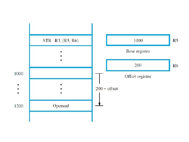
Addressing modes • Pre-indexed mode: LDR Rd, [Rn, #offset] performs Rd ← [[Rn] + offset] LDR Rd, [Rn, Rm] performs Rd ← [[Rn] + [Rm]]
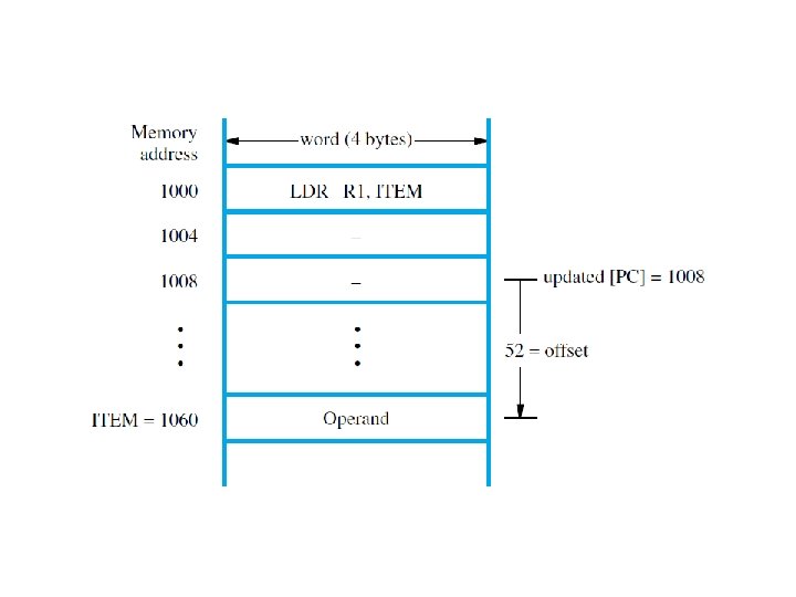
Addressing modes • Relative mode: LDR Rd, ITEM performs Rd ← [[PC] + offset] where offset is calculated by the assembler
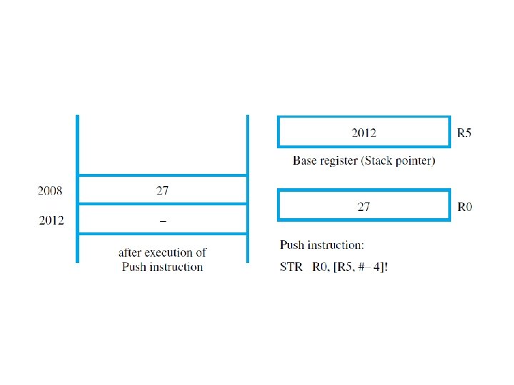
Addressing modes • Pre-indexed with writeback (a generalization of the autodecrement mode): LDR Rd, [Rn, #offset]! performs Rd ← [[Rn] + offset] followed by Rn ← [Rn] + offset (Rm can be used instead of #offset)
Addressing modes • Post-indexed mode (a generalization of the autoincrement mode): LDR Rd, [Rn], #offset performs Rd ← [[Rn]] followed by Rn ← [Rn] + offset (Rm can be used instead of #offset)
Addressing modes • If the offset is given as the contents of Rm, it can be shifted before being used Example: LDR R 0, [R 1, -R 2, LSL #4]! performs R 0 ← [[R 1] - 16 [R 2]] followed by R 1 ← [R 1] - 16 [R 2]
Instructions • Load and Store: LDR and STR for words LDRH and STRH for half words (zero-extended on a Load) LDRB and STRB for bytes (zero-extended on a Load) LDRSH and LDRSB are used for sign-extended Loads (Half words and bytes are positioned at the low-order end of a register)
Instructions • Multiple-word Load and Store: Any subset of the processor registers can be loaded or stored with the Block Transfer instructions LDM and STM Example: LDMIA R 10!, [R 0, R 1, R 6, R 7] If [R 10] = 1000, words at 1000, 1004, 1008, and 1012 are loaded into the registers, and R 10 contains 1016 after all transfers
Instructions • Arithmetic: Assembly language format is OP Rd, Rn, Rm or #offset ADD R 0, R 2, R 4 performs R 0 ← [R 2] [R 4] SUB R 0, R 3, #17 performs R 0 ← [R 3] 17 (immediates are unsigned values in the range 0 to 255)
Instructions • Arithmetic: The second source operand can be shifted or rotated before being used ADD R 0, R 1, R 5, LSL #4 performs R 0 ← [R 1] + 16 × [R 5] Shifts and rotations available: LSL Logical shift left LSR Logical shift right ASR Arithmetic shift right ROR Rotate right
Instructions • Shifting/rotation of the second source operand in arithmetic instructions: The last bit shifted (or rotated) out is written into the C flag A second rotation operation, labeled RRX (Rotate right extended), includes the C flag in the bits being rotated; only rotates by 1 bit (If the second source operand is an immediate value, a limited form of rotation is provided)
Instructions • Arithmetic: MUL R 0, R 1, R 2 performs R 0←[R 1] × [R 2] The low-order 32 bits of the 64 -bit product are written into R 0 For 2’s-complement numbers, the value in R 0 is correct if the product fits into 32 bits
Instructions • Arithmetic: MLA R 0, R 4, R 5, R 6 performs R 0 ← ([R 4] × [R 5]) + [R 6] This Multiply-Accumulate instruction is useful in signal-processing applications Other versions of MUL and MLA generate 64 -bit products
Instructions • Move: MOV Rd, Rm performs Rd ← [Rm] MOV Rd, #value performs Rd ← value (The second operand can be shifted/rotated)
Instructions • Move: MVN Rd, Rm or #value loads the bit-complement of [Rm] or value into Rd
Instructions • Implementing Shift and Rotate instructions: MOV Ri, Rj, LSL #4 achieves the same result as the generic instruction: LShift. L Ri, Rj, #4
Instructions • Logic: AND Rd, Rn, Rm performs the bit-wise logical AND of the operands in registers Rn and Rm and writes the result into register Rd ORR (bit-wise logical OR) EOR (bit-wise logical XOR) are also provided
Instructions • Logic: The Bit Clear instruction, BIC, is closely related to the AND instruction The bits of Rm are complemented before they are ANDed with the bits of Rn If R 0 contains the hexadecimal pattern 02 FA 62 CA, and R 1 contains 0000 FFFF, BIC R 0, R 1 results in 02 FA 0000 being written into R 0
Instructions • Test: TST Rn, Rm or #value performs bit-wise logical AND of the two operands, then sets condition code flags TST R 3, #1 sets Z ← 1 if low-order bit of R 3 is 0 sets Z ← 0 if low-order bit of R 3 is 1 (useful for checking status bits in I/O devices)
Instructions • Test: TEQ Rn, Rm or #value performs bit-wise logical XOR of the two operands, then sets condition code flags TEQ R 2, #5 sets Z ← 1 if R 2 contains 5 sets Z ← 0 otherwise
Instructions • Compare: CMP Rn, Rm performs [Rn] - [Rm] and updates condition code flags based on the result
Instructions • Setting condition code flags CMP, TST, and TEQ, always update the condition code flags Arithmetic, Logic, and Move instructions do so only if S is appended to the OP code ADDS updates flags, but ADD does not
Instructions • Adding 64 -bit operands ADC performs R 0, R 1, R 2 (Add with carry) R 0 ← [R 1] + [R 2] + [C] If pairs R 3, R 2 and R 5, R 4 hold 64 -bit operands, ADDS R 6, R 2, R 4 ADC R 7, R 3, R 5 writes their sum into register pair R 7, R 6
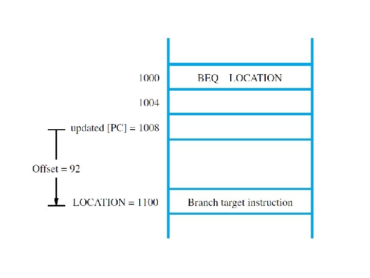
Instructions • Branch: B{condition} LOCATION branches to LOCATION if the settings of the condition code flags satisfy {condition} BEQ LOCATION branches if Z = 1
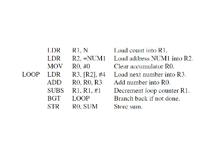
Program • An assembly-language program for adding numbers stored in the memory is shown in the next slide The instruction LDR R 2, =NUM 1 is a pseudoinstruction that loads the 32 -bit address value NUM 1 into R 2 It is implemented using actual instructions
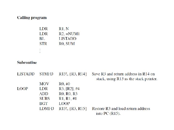
Instructions • Subroutine linkage: BL SUBADDRESS Actions taken: 1. The value of the updated PC is stored in R 14 (LR), the Link register 2. A branch is taken to SUBADDRESS
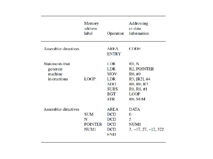
Assembly language • An assembly language program for adding numbers is given in the next slide • Comments: 1. The AREA directive specifies the start of instruction (CODE) and data (DATA) areas 2. The ENTRY directive specifies the start point for program execution
Assembly language • Comments (continued) 3. The combination of the instruction LDR R 2, POINTER and the data declaration POINTER DCD NUM 1 implements the pseudoinstruction LDR R 2, =NUM 1
Pseudoinstructions • Operations specified by pseudoinstructions are implemented with actual machine instructions by the assembler • Example: An immediate is an 8 -bit unsigned value The pseudoinstruction MOV R 0, #-5 is implemented with the actual instruction MVN R 0, #4 (the bit-complement of 4 = 00000100 -5 = 11111011)
Pseudoinstructions • Loading 32 -bit values: The pseudoinstruction LDR Rd, =value loads a 32 -bit value into Rd LDR R 3, =127 is implemented with MOV R 3, #127 (used for “short” values)
Pseudoinstructions • Loading 32 -bit values: LDR R 3, =&A 123 B 456 is implemented with LDR R 3, MEMLOC (instruction) MEMLOC DCD &A 123 B 456 (data) (used for “long” values, including addresses)
Pseudoinstructions • Loading 32 -bit address label values: If the address is “close” to the current value of the program counter (R 15), the ADR pseudoinstruction can be used ADR Rd, LOCATION is implemented with ADD Rd, R 15, #offset, or SUB Rd, R 15, #offset (offset is calculated by the assembler)