AP Physics Magnetic Fields 2 nd SEMESTER WEEK


 Opposes.")


- Slides: 66
AP Physics Magnetic Fields 2 nd SEMESTER, WEEK 10 -11 -12 Mr. Crofoot RIM High School
Induction and Inductance 4/17/17 Interactive Notebook, Write on page 52 Induced Electric Fields • A ring conductor develops a current in a changing magnetic field. • Therefore, an electric field must be present to do the work of moving the electrons. • Even if the conducting ring were not present, the changing magnetic field produces an electric field.
Induction and Inductance 4/17/17 Interactive Notebook, Write on page 52
Induction and Inductance 4/17/17 Interactive Notebook, Write on page 52
Induction and Inductance 4/17/17 Interactive Notebook, Practice on page 53 Do: Page 804 Checkpoint 4 Page 820 Problem 27 Page 820 Problem 29
Induction and Inductance 4/18/17 Starter Plicker Electric Field lines from static charges start on positive charges and end on negative charges. Electric Field lines induced from a changing magnetic field – a) Spiral forward in the direction of the increasing magnetic field b) Spiral forward in the direction of the decreasing magnetic field c) Make a closed loop in the direction opposite the right hand rule (opposite thumb pointing in direction of increasing magnetic field – fingers pointing in the direction of the electric field) d) Make a closed loop in the direction of the right hand rule (thumb pointing in direction of increasing magnetic field – fingers pointing in the direction of the electric field)
Induction and Inductance 4/18/17 Interactive Notebook, Write on page 54
Induction and Inductance 4/18/17 Interactive Notebook, Write on page 54
Induction and Inductance 4/18/17 Interactive Notebook, Write on page 55
Induction and Inductance 4/18/17 Interactive Notebook, Write on page 55 CORRECTION
Induction and Inductance 4/18/17 Interactive Notebook, Practice on page 56 Do: Page 810 Checkpoint 6 Page 820 Question 51 LR Demonstration
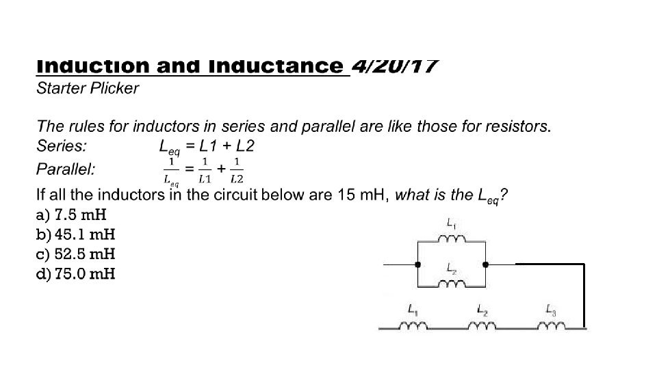
Induction and Inductance 4/20/17 Interactive Notebook, Write on page 57
Induction and Inductance 4/20/17 Interactive Notebook, Write on page 57
Induction and Inductance 4/20/17 Interactive Notebook, Write on page 57
Induction and Inductance 4/20/17 Interactive Notebook, Write on page 58
Induction and Inductance 4/20/17 Interactive Notebook, Write on page 58
Induction and Inductance 4/20/17 Interactive Notebook, Write on page 59 Mutual Induction • Mutual induction is the Emf induced in coil 2 by the changing magnetic flux established by the changing current in coil 1. • Recall the Self Induction is the opposing Emf in coil 1 by changing current in coil 1.
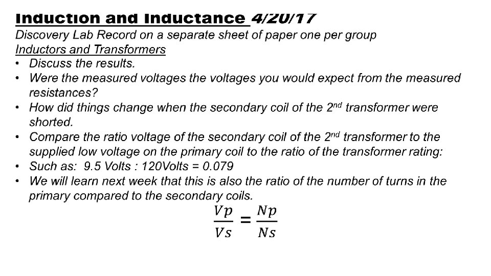
Induction and Inductance 4/20/17 Discovery Lab Record on a separate sheet of paper one per group Inductors and Transformers • Obtain two AC transforms. • Plug the lowest voltage transformer in and use it as a source of AC power. • Use the second transformer in the circuit shown in series with a 150 ohm resistor. • Make the following measurements. 1. Resistance of 150 ohm Resistor: 2. Resistance of primary coil of 2 nd transformer: 3. Resistance of these in series: With the 1 st transformer supplying voltage across the resistor and primary coil of 2 nd transformer. Be sure secondary of 2 nd transformer are not shorted. 1. Voltage across the Resistor 2. Voltage across the primary coil of 2 nd transformer: 3. Voltage of these in series 4. Voltage of the secondary coil of 2 nd transformer. 5. Repeat 1 -6 with the wires of the secondary coil of 2 nd transformer shorted.
Induction and Inductance 4/20/17 Interactive Notebook, Practice on page 60 Do: Page 822 Question 63, 65, 68, 69
= 5. 00Ω = 12. 0 V = 500 m. H
Electromagnetic Oscillations 4/24/17 Interactive Notebook, Write on page 61
Electromagnetic Oscillations 4/24/17 Interactive Notebook, Write on page 61 LC Circuit • The energy oscillation in an LC circuit would go on infinitely if there were no resistance. • The magnitude of the current or voltage with respect to time behaves sinusoidal. • An analogy to an oscillating block and spring can be made. x→ q v→ i K → 1/C m→ L Block-Spring LC Oscillator Capacitor Block Inductor
Electromagnetic Oscillations 4/24/17 Interactive Notebook, Write on page 61 LC Circuit x→ q v→ i K → 1/C m→ L Block-Spring LC Oscillator Capacitor Block Inductor
Electromagnetic Oscillations 4/24/17 Interactive Notebook, Practice on page 62 Do: Page 829 Check Point 1 Page 853 -854 Question 3 Page 855 Problem 5
500 m. H = = 500 m. F
Electromagnetic Oscillations 4/25/17 Interactive Notebook, Write on page 63 LC Circuit • Continuing our analogy to Newtonian Block and Spring, the time oscillations of charge and current are described by: q = Q cos(ωt + Ф) i = dq/dt = - ωQ sin(ωt + Ф) • ωQ is the maximum amplitude of the current, I. i=- I sin(ωt + Ф) • By convention, q and i are instantaneous charge and current; Q and I are maximum charge and current.
Electromagnetic Oscillations 4/25/17 Interactive Notebook, Write on page 63
Electromagnetic Oscillations 4/25/17 Interactive Notebook, Write on page 63
Electromagnetic Oscillations 4/25/17 Interactive Notebook, Write on page 63
Electromagnetic Oscillations 4/25/17 Interactive Notebook, Write on page 63
Electromagnetic Oscillations 4/25/17 Demonstration of damped oscillation of RLC circuit
Electromagnetic Oscillations 4/25/17 Interactive Notebook, Write on page 64
Electromagnetic Oscillations 4/25/17 Interactive Notebook, Write on page 64 • When the two angular frequencies match, the circuit is said to be in resonance.
Electromagnetic Oscillations 4/25/17 Interactive Notebook, Practice on page 65 Do: Page 833 Check Point 2 Page 853 -854 Question 5 Page 855 Problem 25
Electromagnetic Oscillations 4/27/17 Starter Plicker The damped charge with respect to time on a capacitor in an RLC circuit is described by the equation: q = Q e-Rt/2 L cos(ω’t + Ф) What part of the equation determines the damping and prevents the oscillations from going on forever? a) cos(ω’t + Ф) b) Ф c) Q d) e-Rt/2 L
Electromagnetic Oscillations 4/27/17 Interactive Notebook, Write on page 66
Electromagnetic Oscillations 4/27/17 Interactive Notebook, Write on page 66
Electromagnetic Oscillations 4/27/17 Interactive Notebook, Write on page 66
Electromagnetic Oscillations 4/28/17 Interactive Notebook, Write on page 68 • The phasors for the three simple AC driven circuits are as shown below.
Electromagnetic Oscillations 4/27/17 Interactive Notebook, Practice on page 67 Do: Page 838 -842 Check Point 3, 5, 6 Page 855 Problem 29
Electromagnetic Oscillations 4/28/17 Starter Plicker If the red phasor represents the current in each component, which set of phasors describe V(resistor), V(capacitor), V(inductor) in AC driven circuits? A. Green, Purple, Blue B. Green, Blue, Purple C. Purple, Green, Blue D. Purple, Blue, Green 15 10 Axis Title 5 -10 -5 0 V(A) 0 -5 -10 -15 Current Axis Title 5 10 15 V(B) V(C)
Electromagnetic Oscillations 4/28/17 Interactive Notebook, Write on page 68 • The phasors for the three simple AC driven circuits are as shown below. • Today, we will extend that analysis to more complicated circuits.
Electromagnetic Oscillations 4/28/17 Interactive Notebook, Write on page 68 • Now we will apply the alternating Emf to a full RLC circuit. Emf = Emf(max) sin ωdt • The current is the same throughout the circuit: i = I sin (ωdt-Ф) • The phasor representation of current and the Emf at each component is displayed. • The x-axis represents the cyclic time. • The length of each arrow represents the maximum for that variable. • The projection of the arrow on the y-axis represents the instantaneous value of the variable.
Electromagnetic Oscillations 4/28/17 Interactive Notebook, Write on page 68 • Since the RLC circuit is driven by the AC Emf, it is not damped and takes on the frequency, ωd. • Emf(max) is the phasor labelled Vm, and it’s length is the amplitude of the driving Emf. It’s projection on the y-axis is the value of the driving Emf at any time t. • Since Emf=VR + VC + VL, the Vm phasor is the vector sum of the other three. • Since VL and VC are opposite direction we call their difference VL-VC a single phasor that we will add to the VR phasor vector to get Vm. • Applying Pythagorean Theorem: Emf(max)2 = VR 2 +(VL-VC)2 Vm=IZ
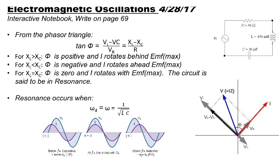
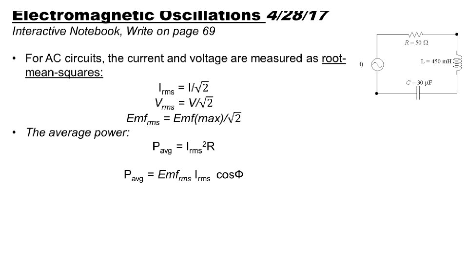
Electromagnetic Oscillations 4/28/17 Interactive Notebook, Write on page 69
Electromagnetic Oscillations 4/28/17 Interactive Notebook, Practice on page 70 Do: Page 854 Question 10 Page 857 Problem 41, 51, 61
Electromagnetic Oscillations 5/1/17 Starter Plicker Your house transformer converts 110 kv to 110 v. If the power line can deliver 0. 05 amps to the transformer, what is the maximum current available in your house? A. 5 x 10 -5 amps B. 50 amps C. 500 amps D. 5000 amps
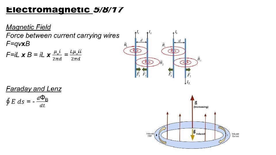
Because magnetic field lines must start and end at a point, the net magnetic flux must always be zero.
B B • Because of the negative sign, Faraday’s Law (Lenz’s Law) Opposes.
Electromagnetic Oscillations 5/1/17 Interactive Notebook, Practice on page 72 Do: Page 863 and 866 CP 1 and 2 Page 882 Question 1 Page 883 Problem 1
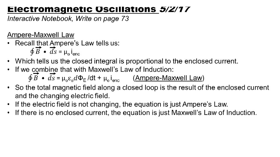
Electromagnetic Oscillations 5/2/17 Interactive Notebook, Write on page 74 Maxwell’s Laws Name Equation Meaning Gauss’ Law for Electricity Relates the net electric field to the net enclosed electric charge Gauss’ Law for Magnetism Relates the net magnetic flux to the net enclosed magnetic charge Faraday’s Law Relates the induced electric field to the changing magnetic flux Ampere’-Maxwell Law Relates the induced magnetic field to the changing electric flux and the current
Electromagnetic Oscillations 5/2/17 Interactive Notebook, Practice on page 75 Do: Page 884 Problem 5, 12
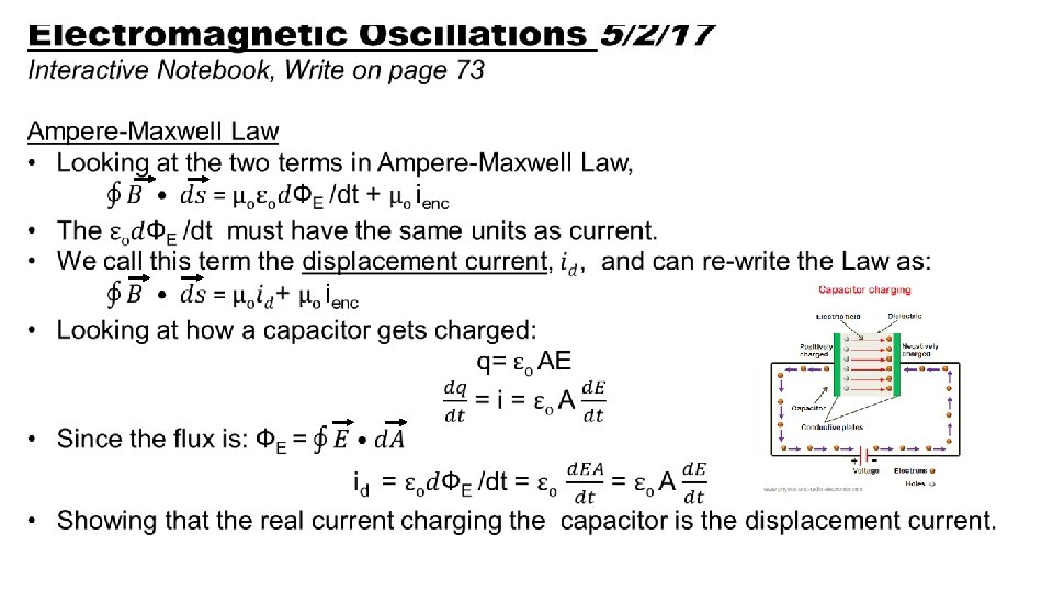
Electromagnetic Oscillations 5/3/17 Starter Plicker Which of Maxwell’s equations can be used to determine the electric field in a capacitor? A. Guass’ Law for Electricity B. Guass’ Law for Magnetism C. Faraday’s Law D. Ampere-Maxwell Law
Electromagnetic Oscillations 5/4/17 Starter Plicker Yesterday, Troy reminded us Gauss’ Law uses an area vector. What direction does that area vector point? A. Parallel to the area surface using a right hand rule B. Perpendicular to the area surface out of the closed surface C. Parallel to the area surface using a left hand rule D. Perpendicular to the area surface into of the closed surface
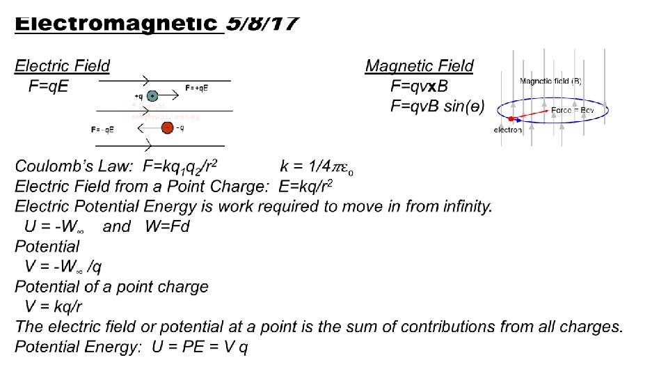
Electromagnetic 5/8/17 Maxwell’s Laws Name Equation Meaning Gauss’ Law for Electricity Relates the net electric field to the net enclosed electric charge Gauss’ Law for Magnetism Relates the net magnetic flux to the net enclosed magnetic charge Faraday’s Law Relates the induced electric field to the changing magnetic flux Ampere’-Maxwell Law Relates the induced magnetic field to the changing electric flux and the current