ANTRC170V3 Training Unit 2 Introduction to the ANTRC170


- Slides: 32

AN/TRC-170(V)3 Training Unit 2 Introduction to the AN/TRC-170

Introduction to the AN/TRC-170(V)3 Objectives: • • • Purpose Capabilities and Limitations Major components of the AN/TRC-170(V)3 Digital Troposcatter Communications System (TRC-170) Intro to TRC-170 AN/TRC-170(V)3 Training 2

Purpose of the AN/TRC-170(V)3 • • Air or Ground Transportable Tropospheric Scatter Microwave Radio Terminal Secure Digital Trunking All Major Units are Rack Mounted Intro to TRC-170 AN/TRC-170(V)3 Training 3

AN/TRC-170(V)3 Training 4

Shelter Exterior Road-side Intro to TRC-170 Curb-side AN/TRC-170(V)3 Training 5

Shelter Interior Road-side Rear Intro to TRC-170 Curb-side Front AN/TRC-170(V)3 Training Rear 6

Capabilities and Limitations • Frequency Range: 4. 4 – 5. 0 GHz • Transmission Range: 100 miles Intro to TRC-170 AN/TRC-170(V)3 Training 7

Capabilities and Limitations Output Power • • • Tropo Maximum 2 Kilowatts (k. W) Tropo Nominal 1 k. W Line of Sight minimum. 4 w Intro to TRC-170 AN/TRC-170(V)3 Training 8

Capabilities and Limitations • • • Data Bandwidth Antenna Gain Diversity Intro to TRC-170 AN/TRC-170(V)3 Training 9

Diversity Modes Non-Diversity • All AN/TRC-170 versions are capable of Nondiversity Dual Diversity • All AN/TRC-170 versions are capable of Dualdiversity Quad-Diversity • Only the AN/TRC-170(V)2 is capable of Quaddiversity Intro to TRC-170 AN/TRC-170(V)3 Training 10

Non-Diversity Receiving Transmitting Transmit & Receive Intro to TRC-170 Transmit Signal AN/TRC-170(V)3 Training Transmit & Receive 11

Dual Diversity Receive Transmit & Receive Intro to TRC-170 Signal AN/TRC-170(V)3 Training Transmit & Receive 12

TRC-170(V)3 System Block Diagram Intro to TRC-170 AN/TRC-170(V)3 Training 13

Major Components • • • Transmitter Receiver CS 6716 Modem Upgrade Digital Voice Orderwire (DVOW) with KY-58 Quick Reaction Antenna Intro to TRC-170 AN/TRC-170(V)3 Training 14

TRC-170(V)3 Transmitter Block Diagram Intro to TRC-170 AN/TRC-170(V)3 Training 15

Transmitter Roadside High Power Amplifier (HPA) Up-converter Dual RF Synthesizer Rear Intro to TRC-170 AN/TRC-170(V)3 Training Front 16

TRC-170(V)3 Receiver Block Diagram Antenna No 1 Up Conv Inhibit H Frequency Synthesizer 3 A 2 AZ/EL Sensor LO LO RCV-3 RF Noise Source 3 A 4 RCV-3 IF Down Converter No 1 RCV-1 IF TX IF-Test From Modulator FO-35 RF Noise RCV-1 RF Antenna No 2 Down Converter No 3 IF Test Panel 7 A 5 RCVR-1 IF To Demod H RCVR-3 IF Synth Fault To Alarm Monitor FO-41 AZ/EL RAAM Intro to TRC-170 Conv Fault Config (Noise) to Alarm Monitor FO-41 RSL AZ/EL Alarm Monitor Panel 7 A 2 AN/TRC-170(V)3 Training CONFIG (LPBK) To Alarm Monitor FO-41 17

Receiver Down-converter (2 per shelter) output 70 MHz Intro to TRC-170 Dual RF Synthesizer (1 per shelter) output 4. 4 to 5. 0 GHz AN/TRC-170(V)3 Training 18

CS 6716 Modem Upgrade Curbside • • IF DATA Patch Panel CS 6716 Modem Versa. Mux 4000 Oscillator Amplifier Converter (OAC) -170 D • 48 Volts Direct Current (VDC) Power Supply ™ Front Intro to TRC-170 AN/TRC-170(V)3 Training Rear 19

IF Data Patch Panel IF Section Intro to TRC-170 Data Section AN/TRC-170(V)3 Training Orderwire Section 20

CS 6716 Modem Alarm and Status Indicators Intro to TRC-170 Keypad Alphanumeric Display AN/TRC-170(V)3 Training 21

CS 6716 Modem With the access panel opened (display board) Intro to TRC-170 AN/TRC-170(V)3 Training 22

Versa. Mux™ 4000 front panel Display LEDs Keypads Intro to TRC-170 Power AN/TRC-170(V)3 Training 23

Versa. Mux™ 4000 back panel Intro to TRC-170 AN/TRC-170(V)3 Training 24

OAC-170 D Oscillator Amplifier Converter (OAC) • 1 per shelter • Contains 4 IF amplifiers • Selectable IF filter bandwidths • Contains redundant oscillators Gain Adjusts Intro to TRC-170 Filter bandwidth Oscillator Select AN/TRC-170(V)3 Training 25

48 volt power supply • • With 2 separate power supply modules Hot swappable Intro to TRC-170 AN/TRC-170(V)3 Training 26

DAR Equipment Intro to TRC-170 AN/TRC-170(V)3 Training 27

Digital Group Multiplex Baseband PP LGM GM TGM LGM Intro to TRC-170 AN/TRC-170(V)3 Training 28

Digital Voice Orderwire (DVOW) with KY-58 Intro to TRC-170 AN/TRC-170(V)3 Training 29

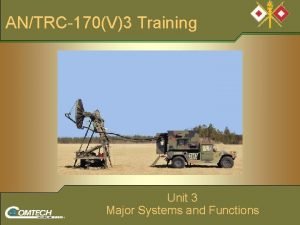
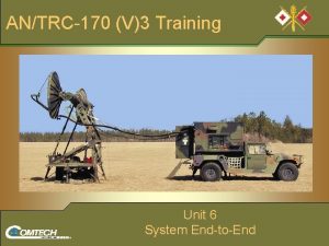
Quick Reaction Antenna (QRA) The antenna is built onto the trailer chassis Intro to TRC-170 AN/TRC-170(V)3 Training 30

Quick Reaction Antenna • M 116 A 2 Trailer Chassis • 6 ft (180 cm) Parabolic Dish Reflectors Intro to TRC-170 AN/TRC-170(V)3 Training 31

Questions? Intro to TRC-170 AN/TRC-170(V)3 Training 32
 Unit 6 review questions
 Hát kết hợp bộ gõ cơ thể
 Slidetodoc
 Bổ thể
 Tỉ lệ cơ thể trẻ em
 Voi kéo gỗ như thế nào
 Glasgow thang điểm
 Bài hát chúa yêu trần thế alleluia
 Kể tên các môn thể thao
 Thế nào là hệ số cao nhất
 Các châu lục và đại dương trên thế giới
 Công thức tính thế năng
 Trời xanh đây là của chúng ta thể thơ
 Cách giải mật thư tọa độ
 Phép trừ bù
 Phản ứng thế ankan
 Các châu lục và đại dương trên thế giới
 Thể thơ truyền thống
 Quá trình desamine hóa có thể tạo ra
 Một số thể thơ truyền thống
 Cái miệng nó xinh thế chỉ nói điều hay thôi
 Vẽ hình chiếu vuông góc của vật thể sau
 Nguyên nhân của sự mỏi cơ sinh 8
 đặc điểm cơ thể của người tối cổ
 Ví dụ giọng cùng tên
 Vẽ hình chiếu đứng bằng cạnh của vật thể
 Fecboak
 Thẻ vin
 đại từ thay thế
 điện thế nghỉ
 Tư thế ngồi viết
 Diễn thế sinh thái là
 Dạng đột biến một nhiễm là


