Announcements Assignment 0 solutions posted Assignment 1 due


=ZIS(jω) • Voltage and current not in")
 from KVL • Voltage and")


= Transfer function Since we are interested in frequency response, use phasors.")


 and (c) are")

 filters Measuring voltage output signal over L and C Low frequencies, C")

- Slides: 18
Announcements • Assignment 0 solutions posted • Assignment 1 due on Thursday • DC circuit Lab reports due to Sajan today and tomorrow • This week’s lab – AC circuits
Lecture 6 Overview • AC Circuit Analysis • Filters
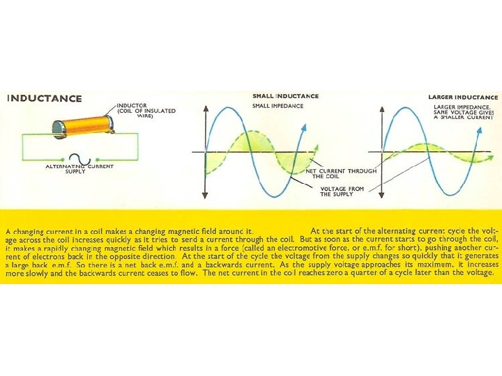
The Story so far… Generalized Ohm's Law: VS(jω)=ZIS(jω) • Voltage and current not in phase: • Current leads voltage by 90 degrees • Impedance of Capacitor decreases with increasing frequency • Voltage and current not in phase: • Current lags voltage by 90 degrees • Impedance of Inductor increases with increasing frequency • Voltage and current in phase • no frequency dependece
Inductors in AC circuits Inductive Load (back emf ) from KVL • Voltage and current not in phase: • Current lags voltage by 90 degrees • Impedance of Inductor increases with increasing frequency http: //arapaho. nsuok. edu/%7 Ebradfiel/p 1215/fendt/phe/accircuit. htm
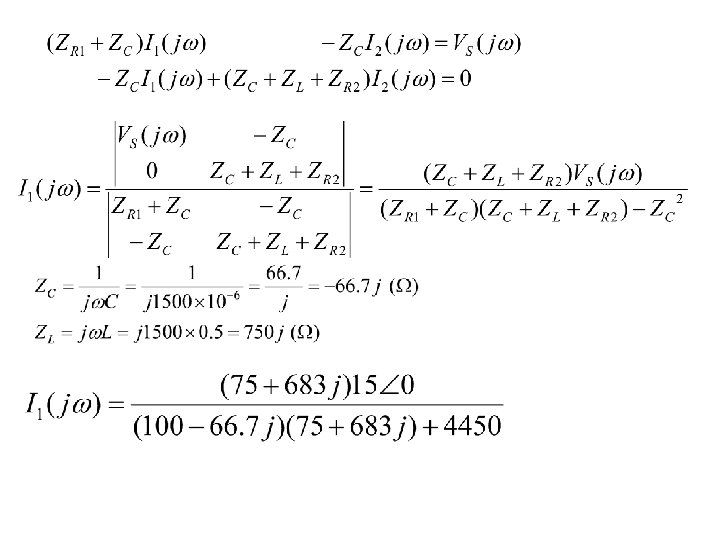
AC circuit analysis • Effective impedance: example • Procedure to solve a problem – – Identify the sinusoid and note the excitation frequency Convert the source(s) to complex/phasor form Represent each circuit element by it's AC impedance Solve the resulting phasor circuit using standard circuit solving tools (KVL, KCL, Mesh etc. ) – Convert the complex/phasor form answer to its time domain equivalent
Example
Top: Bottom:
Transfer Function Hv(jω)= Transfer function Since we are interested in frequency response, use phasors. VL(jω) is a phase-shifted and amplitude -scaled version of VS(jω) Hv(jω) describes what the phase shift and amplitude scaling are.
Low pass filters • RC low-pass filter: preserves lower frequencies, attenuates frequencies above the cutoff frequency ω0=1/RC.
Low pass filters Break frequency ω=ω0=1/RC, HV=1/√ 2 N. B. decibels: For voltage For power
Build other filters by combining impedance response
Which of the following is a low-pass filter? What happens to the output voltage when ω→ 0 (DC condition)? Answer: (c)
Which of the following are high-pass or low-pass filters? Answers: (b) and (c) are highpass; (a) and (d) are low-pass
RLC Band-pass filters Measuring voltage output signal over R, Vr Low frequencies, C open, L shorted, Vr minimum High frequency, C shorted, L open, Vr minimum so, at high and low frequencies, see an open circuit - Vr minimum C L
Band-stop (Notch) filters Measuring voltage output signal over L and C Low frequencies, C open, L shorted, Vlc maximum High frequency, C shorted, L open, Vlcmaximum so, at high and low frequencies, see an open circuit - Vlc maximum
Another Example: Measuring voltage output signal over L and C, but this time in parallel (i. e. at high and low frequencies, see a short - V 0=0)