ANNEX MAC PETRAIII Review Meeting DESY 29 th
- Slides: 10
ANNEX MAC PETRA-III Review Meeting, DESY, 29 th November 2006 WP 1. 04, Michael Ebert
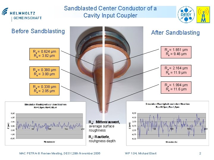
Sandblasted Center Conductor of a Cavity Input Coupler Before Sandblasting After Sandblasting Ra = 0. 624 µm Rz = 3. 82 µm Ra = 1. 651 µm Rz = 9. 46 µm Ra = 0. 380 µm Rz = 3. 00 µm Ra = 2. 164 µm Rz = 11. 9 µm Ra = 0. 338 µm Rz = 2. 05 µm Ra = 1. 994 µm Rz = 11. 6 µm Ra: Mittenrauwert, average surface roughness Rz: Rautiefe, rouhgness depth MAC PETRA-III Review Meeting, DESY, 29 th November 2006 WP 1. 04, Michael Ebert 2
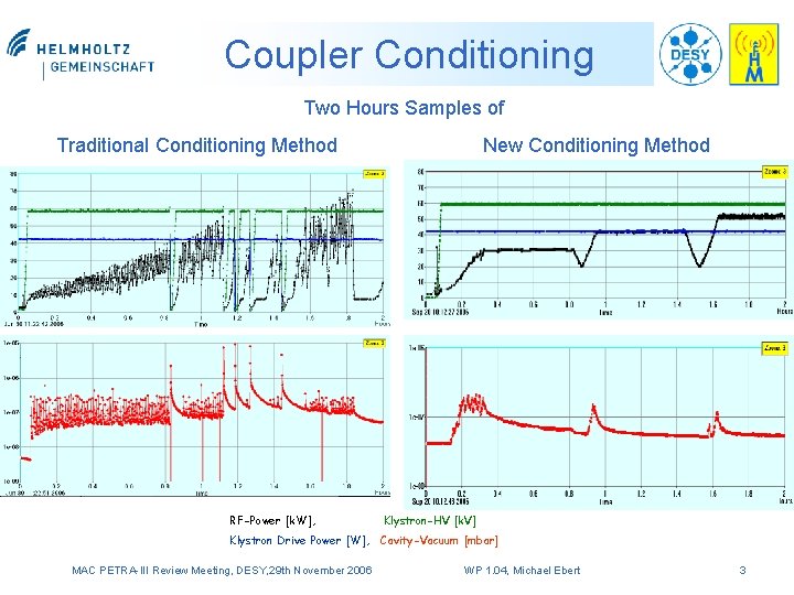
Coupler Conditioning Two Hours Samples of Traditional Conditioning Method RF-Power [k. W], New Conditioning Method Klystron-HV [k. V] Klystron Drive Power [W], Cavity-Vacuum [mbar] MAC PETRA-III Review Meeting, DESY, 29 th November 2006 WP 1. 04, Michael Ebert 3
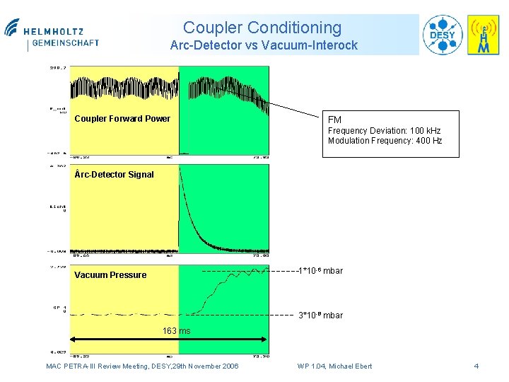
Coupler Conditioning Arc-Detector vs Vacuum-Interock Coupler Forward Power FM Frequency Deviation: 100 k. Hz Modulation Frequency: 400 Hz rc-Detector Signal 1*10 -6 mbar Vacuum Pressure 3*10 -8 mbar 163 ms MAC PETRA-III Review Meeting, DESY, 29 th November 2006 WP 1. 04, Michael Ebert 4
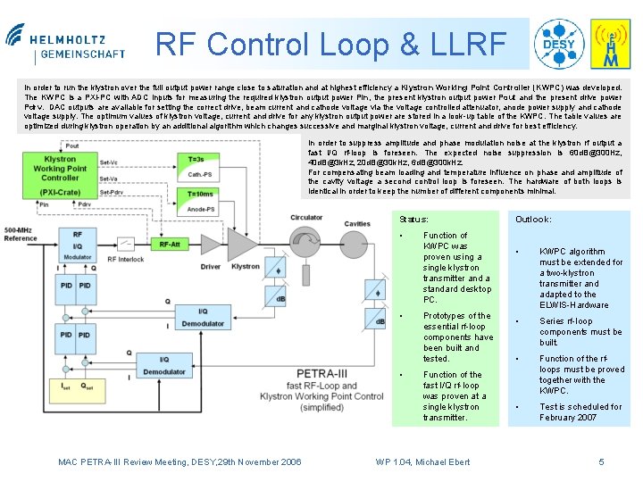
RF Control Loop & LLRF In order to run the klystron over the full output power range close to saturation and at highest efficiency a Klystron Working Point Controller (KWPC) was developed. The KWPC is a PXI-PC with ADC inputs for measuring the required klystron output power Pin, the present klystron output power Pout and the present drive power Pdrv. DAC outputs are available for setting the correct drive, beam current and cathode voltage via the voltage controlled attenuator, anode power supply and cathode voltage supply. The optimum values of klystron voltage, current and drive for any klystron output power are stored in a look-up table of the KWPC. The table values are optimized during klystron operation by an additional algorithm which changes successive and marginal klystron voltage, current and drive for best efficiency. In order to suppress amplitude and phase modulation noise at the klystron rf output a fast I/Q rf-loop is foreseen. The expected noise suppression is 60 d. B@300 Hz, 40 d. B@3 k. Hz, 20 d. B@30 k. Hz, 6 d. B@300 k. Hz. For compensating beam loading and temperature influence on phase and amplitude of the cavity voltage a second control loop is foreseen. The hardware of both loops is identical in order to keep the number of different components minimal. Status: • • • MAC PETRA-III Review Meeting, DESY, 29 th November 2006 Function of KWPC was proven using a single klystron transmitter and a standard desktop PC. Prototypes of the essential rf-loop components have been built and tested. Function of the fast I/Q rf-loop was proven at a single klystron transmitter. WP 1. 04, Michael Ebert Outlook: • KWPC algorithm must be extended for a two-klystron transmitter and adapted to the ELWIS-Hardware • Series rf-loop components must be built. • Function of the rfloops must be proved together with the KWPC. • Test is scheduled for February 2007 5
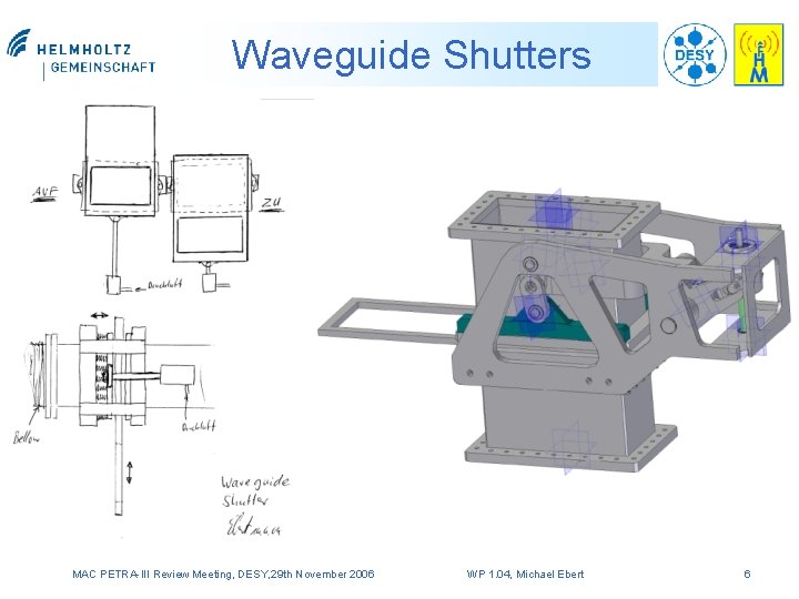
Waveguide Shutters MAC PETRA-III Review Meeting, DESY, 29 th November 2006 WP 1. 04, Michael Ebert 6
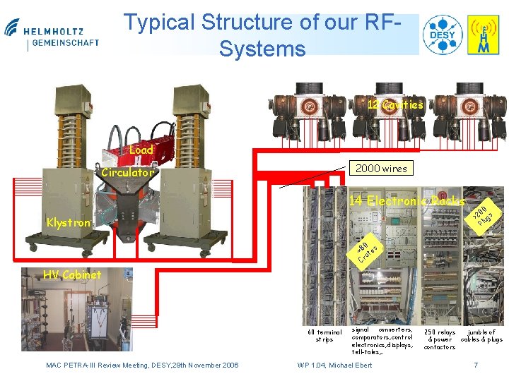
Typical Structure of our RFSystems 12 Cavities Load 2000 wires Circulator 14 Electronic Racks Klystron 00 >2 ugs Pl 0 ~8 tes a Cr HV Cabinet 60 terminal strips MAC PETRA-III Review Meeting, DESY, 29 th November 2006 signal converters, comparators, control electronics, displays, tell-tales, … WP 1. 04, Michael Ebert 250 relays jumble of & power cables & plugs contactors 7
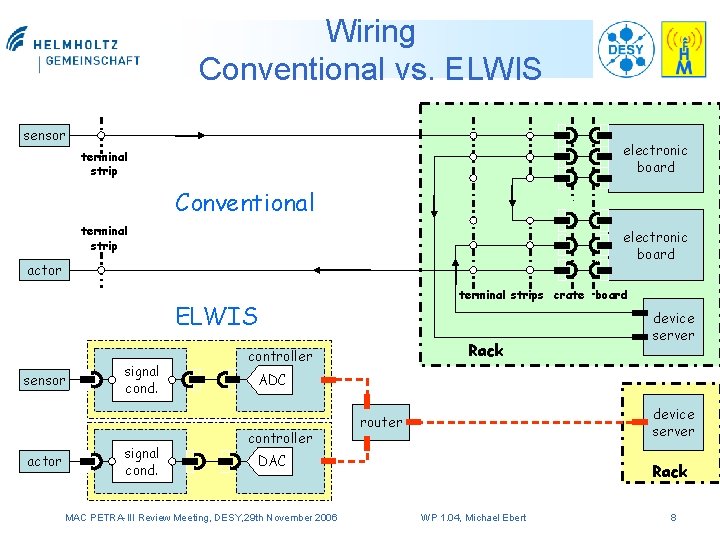
Wiring Conventional vs. ELWIS sensor electronic board terminal strip Conventional terminal strip electronic board actor terminal strips crate board ELWIS sensor actor signal cond. Rack controller device server ADC controller device server router DAC MAC PETRA-III Review Meeting, DESY, 29 th November 2006 Rack WP 1. 04, Michael Ebert 8
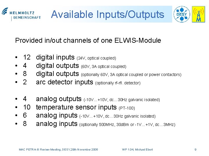
Available Inputs/Outputs Provided in/out channels of one ELWIS-Module • • 12 4 8 2 digital inputs (24 V, optical coupled) digital outputs (60 V, 3 A optical coupled) digital outputs (optionally 60 V, 3 A optical coupled or power contactors) arc detector inputs (optionally rf-rfl. detector) • • 4 10 6 8 analog outputs (-10 V…+10 V, dc… 30 Hz galvanic isolated) temperature sensor inputs (PT-100) analog inputs (-10 V…+10 V, dc… 30 Hz galvanic isolated) analog inputs (optionally 500 MHz, 30 d. Bm or -1 V…+1 V, dc… 3 MHz) MAC PETRA-III Review Meeting, DESY, 29 th November 2006 WP 1. 04, Michael Ebert 9
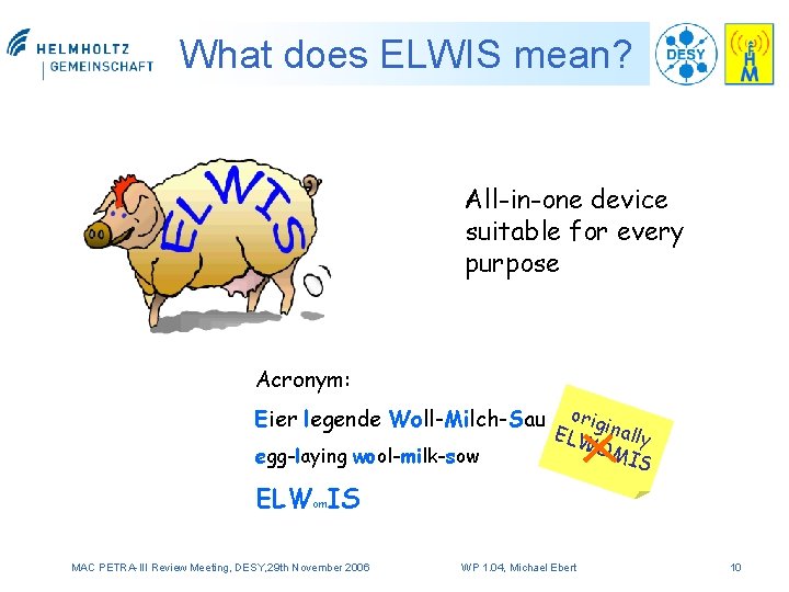
What does ELWIS mean? All-in-one device suitable for every purpose Acronym: Eier legende Woll-Milch-Sau egg-laying wool-milk-sow orig ELW inally OM IS ELWom. IS MAC PETRA-III Review Meeting, DESY, 29 th November 2006 WP 1. 04, Michael Ebert 10